EP0440246A1 - Bremsvorrichtung für fadenförmiges Gut - Google Patents
Bremsvorrichtung für fadenförmiges Gut Download PDFInfo
- Publication number
- EP0440246A1 EP0440246A1 EP91101324A EP91101324A EP0440246A1 EP 0440246 A1 EP0440246 A1 EP 0440246A1 EP 91101324 A EP91101324 A EP 91101324A EP 91101324 A EP91101324 A EP 91101324A EP 0440246 A1 EP0440246 A1 EP 0440246A1
- Authority
- EP
- European Patent Office
- Prior art keywords
- strand
- braking
- roll
- fact
- brake
- Prior art date
- Legal status (The legal status is an assumption and is not a legal conclusion. Google has not performed a legal analysis and makes no representation as to the accuracy of the status listed.)
- Granted
Links
- 239000000463 material Substances 0.000 claims description 7
- 230000000452 restraining effect Effects 0.000 claims 3
- 230000001419 dependent effect Effects 0.000 abstract description 30
- 230000008901 benefit Effects 0.000 description 7
- 238000010586 diagram Methods 0.000 description 7
- 230000008859 change Effects 0.000 description 6
- 230000000694 effects Effects 0.000 description 3
- 230000007246 mechanism Effects 0.000 description 3
- 239000004020 conductor Substances 0.000 description 2
- 230000007423 decrease Effects 0.000 description 2
- 238000000034 method Methods 0.000 description 2
- 230000008569 process Effects 0.000 description 2
- 230000005417 remagnetization Effects 0.000 description 2
- 238000004804 winding Methods 0.000 description 2
- 230000006835 compression Effects 0.000 description 1
- 238000007906 compression Methods 0.000 description 1
- 230000008878 coupling Effects 0.000 description 1
- 238000010168 coupling process Methods 0.000 description 1
- 238000005859 coupling reaction Methods 0.000 description 1
- 230000003247 decreasing effect Effects 0.000 description 1
- 230000005484 gravity Effects 0.000 description 1
- XEEYBQQBJWHFJM-UHFFFAOYSA-N iron Substances [Fe] XEEYBQQBJWHFJM-UHFFFAOYSA-N 0.000 description 1
- 229910052742 iron Inorganic materials 0.000 description 1
- 239000002184 metal Substances 0.000 description 1
- 229910052751 metal Inorganic materials 0.000 description 1
- 238000012544 monitoring process Methods 0.000 description 1
- 230000007704 transition Effects 0.000 description 1
Images


Classifications
-
- F—MECHANICAL ENGINEERING; LIGHTING; HEATING; WEAPONS; BLASTING
- F16—ENGINEERING ELEMENTS AND UNITS; GENERAL MEASURES FOR PRODUCING AND MAINTAINING EFFECTIVE FUNCTIONING OF MACHINES OR INSTALLATIONS; THERMAL INSULATION IN GENERAL
- F16D—COUPLINGS FOR TRANSMITTING ROTATION; CLUTCHES; BRAKES
- F16D63/00—Brakes not otherwise provided for; Brakes combining more than one of the types of groups F16D49/00 - F16D61/00
-
- B—PERFORMING OPERATIONS; TRANSPORTING
- B65—CONVEYING; PACKING; STORING; HANDLING THIN OR FILAMENTARY MATERIAL
- B65H—HANDLING THIN OR FILAMENTARY MATERIAL, e.g. SHEETS, WEBS, CABLES
- B65H59/00—Adjusting or controlling tension in filamentary material, e.g. for preventing snarling; Applications of tension indicators
- B65H59/10—Adjusting or controlling tension in filamentary material, e.g. for preventing snarling; Applications of tension indicators by devices acting on running material and not associated with supply or take-up devices
- B65H59/16—Braked elements rotated by material
-
- B—PERFORMING OPERATIONS; TRANSPORTING
- B65—CONVEYING; PACKING; STORING; HANDLING THIN OR FILAMENTARY MATERIAL
- B65H—HANDLING THIN OR FILAMENTARY MATERIAL, e.g. SHEETS, WEBS, CABLES
- B65H59/00—Adjusting or controlling tension in filamentary material, e.g. for preventing snarling; Applications of tension indicators
-
- B—PERFORMING OPERATIONS; TRANSPORTING
- B65—CONVEYING; PACKING; STORING; HANDLING THIN OR FILAMENTARY MATERIAL
- B65H—HANDLING THIN OR FILAMENTARY MATERIAL, e.g. SHEETS, WEBS, CABLES
- B65H59/00—Adjusting or controlling tension in filamentary material, e.g. for preventing snarling; Applications of tension indicators
- B65H59/02—Adjusting or controlling tension in filamentary material, e.g. for preventing snarling; Applications of tension indicators by regulating delivery of material from supply package
- B65H59/04—Adjusting or controlling tension in filamentary material, e.g. for preventing snarling; Applications of tension indicators by regulating delivery of material from supply package by devices acting on package or support
-
- D—TEXTILES; PAPER
- D07—ROPES; CABLES OTHER THAN ELECTRIC
- D07B—ROPES OR CABLES IN GENERAL
- D07B7/00—Details of, or auxiliary devices incorporated in, rope- or cable-making machines; Auxiliary apparatus associated with such machines
- D07B7/02—Machine details; Auxiliary devices
- D07B7/06—Bearing supports or brakes for supply bobbins or reels
-
- B—PERFORMING OPERATIONS; TRANSPORTING
- B65—CONVEYING; PACKING; STORING; HANDLING THIN OR FILAMENTARY MATERIAL
- B65H—HANDLING THIN OR FILAMENTARY MATERIAL, e.g. SHEETS, WEBS, CABLES
- B65H2701/00—Handled material; Storage means
- B65H2701/30—Handled filamentary material
- B65H2701/31—Textiles threads or artificial strands of filaments
Definitions
- the present invention relates to an apparatus for imparting a braking force to an advancing strand.
- strand is intended to encompass all linear structures, such as wires, yarns, bands, ropes, and the like.
- a strand brake is disclosed in U.S. Patent 3,830,050, which relates to a wire stranding machine.
- the known brake is universally usable for the adjustment of the tension of a strand, and it is used in particular for the adjustment of the tension of wires, bands, yarns, etc., which are withdrawn from a freely rotatable supply spool with a brake.
- Such known brakes have the disadvantage that the braking effect and, thus, also the increase of the tension are dependent on the amount of the strand tension.
- Another disadvantage is that despite the control, the tension increases as the spool empties from the full to the empty condition, when the brake is operative on the spool. This increase of tension is larger, the greater the tension is.
- the brake is adjusted to a certain strand tension right from the beginning. This tension is adjusted for the stationary operation to a rated speed; it can nonetheless be too high for the threading of the strand and for the startup of the machine, and can lead to difficulties, in particular to strand breaks. This applies especially to the use of the strand brake in machines in which the strand which is restrained by the brake, subsequently forms a free flying balloon.
- a strand braking apparatus which comprises first braking means for imparting a braking force to the advancing strand which is controlled as a function of the tension of the advancing strand, and second braking means for imparting a braking force to the advancing strand which is controlled as a function of the movement of the advancing strand.
- the first and second braking means are arranged in series along the path of the advancing strand.
- the first braking means comprises a device for monitoring the strand tension together with a brake which is controlled as a function of the strand tension.
- a frequently used braking means of this type is a so-called compensating arm brake.
- Such a brake allows the supply spool of the advancing strand to be braked by a spring force, and the spring force can be relieved as a function of the increasing strand tension which is measured by the compensating arm.
- the strand tension is controlled by a compensating arm, which is pivoted in one direction by gravity or the force of a spring and guides the yarn in a loop, the size of the loop being dependent on the tension of the strand.
- the position of the compensating arm in turn controls the braking force applied to the supply spool.
- electromagnetic brakes are especially suitable, such as, for example, an eddy-current brake.
- an eddy-current brake a magnet performs a movement relative to a soft-iron disc with a layer of an electric conductor.
- eddy currents are induced in the layer of the electric conductor, thereby producing a movement dependent braking moment. Consequently, the eddy-current brake has the advantage that the "threading" of the strand, i.e., the pulling of the strand into the machine is to be carried out under very little tension of the strand, which is only applied by the compensating arm brake.
- Eddy-current brakes for takeup devices are known, note Trade Journal "Draht” 1962, pp. 53-59.
- the present invention is concerned with effecting a combination of a mechanical and a movement dependent brake. Consequently, the produced strand tension is composed of two portions.
- the mechanically produced portion is preferably kept small in relation to the movement dependent portion, and as a result, mechanical troubles, such as, for example, the decreasing diameter during the unwinding process, have only a slight effect on the overall strand tension.
- Essential is that at a speed which remains constant, the larger, movement dependent portion should also remain constant. The overall change of the strand tension resulting from an interference is therefore small.
- the second or movement dependent braking means comprises a roll about which the advancing strand is wound, and an eddy-current brake which comprises a stationary magnet and an electromagnetic disc which is connected to the roll and positioned adjacent the magnet.
- a drive mechanism for example a belt drive with a step-down gear, so as to obtain a high rotational speed of the eddy-current disc and thus high braking forces. If only slight strand tensions are produced, an operative connection in the opposite sense, i.e. a step-up gear, may be provided.
- the eddy-current brake and the other, movement dependent brakes have the further advantage that the balloon tension in cabling, winding and twisting machines can be kept very low at low speeds, and increases only with the speed. This permits a balloon to be formed at low speeds, so that the friction of the strand on the deflecting guide members and thus also the wear on the deflecting guide members remain very small. As a result, it is possible to adapt the braking effect to the speed and to the speed-dependent balloon tension of the strand.
- the second or movement dependent brake may employ a hysteresis brake, which has the advantage that it is possible to adjust a very small braking moment which is exerted by the mechanical compensating arm brake, so that only a very slight change of this braking moment occurs.
- the essential portion of the braking moment is to be produced by the hysteresis brake and is, therefore, constant so that the change of the braking moment, which occurs on the compensating arm brake as the diameter of the spool changes, is slight in relation to the overall braking moment.
- a magnet performs a movement relative to a magnetizable hysteresis material, whereby a continuous remagnetization of the hysteresis material occurs.
- a constant braking moment results which is independent of the relative movement.
- a disadvantage of the above described, movement dependent brakes, in particular the eddy-current brake is that the braking force is not upwardly limited. Consequently, the braking force is also dependent on the operating speed. It is possible, though, to make a compensation by the adjustment of the gap between the primary and the secondary portion of the eddy-current brake.
- another object of the present invention is to limit the braking force during a standstill and additionally also at the startup, but to keep it otherwise constant irrespective of the operating speed. Primarily, it is intended to facilitate threading and to adapt the strand tension to the growth of the balloon which occurs with the startup of the machine.
- the present invention may further include a speed controlled clutch, by which the second braking means is engaged.
- the second braking means is composed of two brakes, which are successively arranged.
- the brake clutch which is speed-dependent. This function can be advantageously performed, for example, by a centrifugal clutch.
- a braking of the non-drive end of the speed-dependent brake clutch by a hysteresis brake has the advantage that the hysteresis brake is free of wear, and otherwise dependent on movement, but substantially independent of speed.
- the adjustment of the speed-dependent brake clutch allows in this embodiment to set any desired, optimal transition between a lower level of the strand tension, which exists at a standstill, and an upper level of the strand tension, which exists during a continuous operation.
- the second braking means be arranged, when viewed in the path of the strand, downstream of the measuring point for the strand tension of the first braking means.
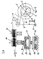
- the strand 1 is withdrawn from a supply spool 2, for example, by a twisting, cabling, processing or rewinding mechanism at a constant speed v.
- the supply spool 2 is mounted on a shaft 4, which is supported for free rotation, and which is provided with a brake. To this end, the supply spool 2 is firmly connected with a brake disk 3.
- the brake disk 3 is partially looped by a brake band 10, which is stationarily attached at point 12 and connected at its other end to a compensating arm 7.
- the compensating arm 7 is a lever which is pivotally connected at a single pivot 8.
- the compensating arm 7 mounts a roll 5, which is partially looped by the strand as it is withdrawn from the supply spool 2.
- the compensating arm 7 is pivoted by a compression spring 9 to the left (counterclockwise) as seen in Figure 1, so that the brake band 10 is tensioned.
- a deflecting roll 6 Arranged in the path of the strand downstream of the compensating arm roll 5 is a deflecting roll 6.
- the deflecting roll 6 is followed by another pair of stationary rolls, comprising a deflecting roll 13 and a measuring roll 14.
- the deflecting roll 13 and measuring roll 14 are supported for free rotation.
- the mounting shaft of the measuring roll 14 is fixedly connected to a metal disc 15, which is designed as an electromagnetic disc. It is also possible to connect the electromagnetic disc 15 with the measuring roll 14 via a drive mechanism with a step-up or a step-down gear.
- Opposite to the electromagnetic disk 15 is the face of a magnet 16. Left between the two is a small gap with a width S, which is preferably adjustable so that the magnet 16 is displaceable in the direction toward the electromagnetic disc 15.
- the full supply spool has an initial diameter D, and the diameter decreases to a diameter d as the strand is withdrawn.
- the strand advancing from the supply spool loops about the compensating arm roll 5 and the deflecting roll 6 respectively at about 180°, so that it is guided in this region in the shape of an S or a Z.
- the compensating arm roll 5 moves substantially parallel between the strand segment advancing to it and the strand segment leaving it. Downstream of the deflecting roll 6, the strand loops several times about both the deflecting roll 13 and the measuring roll 14.
- the strand 1 drives the electromagnetic disc 15 at the rated speed of the machine at a constant speed.
- eddy currents are generated in the disc, and a braking moment is produced, which causes a tension or force F2 on the strand.
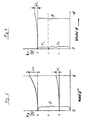
- This tension F2 is plotted in the diagram of Figure 3.
- the force of spring 9 further causes a tension or force F1 on the strand respectively in the strand segment advancing to the compensating arm roll 5 and in the strand segment leaving such roll.
- the force of spring 9 pivots the compensating arm so as to increase the strand loop, which is formed between the supply spool 2 and the stationary deflecting roll 6.
- the brake band 10 is simultaneously tensioned to result in an increased braking of the supply spool 2, with the consequence that a tendency to an increase of the strand tension develops.
- the process is reversed when the strand tension increases.
- the torque exerted by the tension F1 on the supply spool is dependent on the diameter of the latter. Consequently, the tension necessary to overcome a predetermined braking moment is smaller at a large diameter D of the supply spool than at a small diameter d.
- this second portion F2 is selected greater at a predetermined, constant strand speed than the first, tension-dependent portion F1. Consequently, the change delta F1 of this portion is likewise slight in relation to the overall strand tension.
- Illustrated in the diagram of Figure 2 is the variation of the strand tension over the diameter of the supply spool for a compensating arm brake only.
- the amount of the diameter dependent increase delta F1 of the tension can be kept low. However, it is percentagewise large in comparison with the overall strand tension, namely just as large as in the case of a higher selected tension. In the case of a higher selected tension F1, however, a large absolute deviation delta F1 will result as the strand tension varies over the diameter of the spool.
- the combined braking apparatus of the present invention has the advantage that the variation of the strand tension in the course of a winding cycle is small both as to the amount and as to the percentage.
- the electromagnetic disc 15 When designed as a hysteresis brake, the electromagnetic disc 15 is replaced with a disc 15 of a material having a high magnetic retentivity, i.e. a hysteresis material, and which is magnetized by the stationary magnet 16, and which consequently opposes, due to the necessary remagnetization, the relative movement due to a braking movement which is substantially constant.
- a material having a high magnetic retentivity i.e. a hysteresis material
- the measuring roll 14 is connected, via a speed-dependent brake clutch 17, with a further brake 18, which brakes the non-drive end of the brake clutch 17.
- the second braking means comprises the brake clutch 17 and the brake 18.
- the brake clutch is constructed as a centrifugal clutch.
- the shaft of the measuring roll 14 is provided with pivot levers 19, which are connected to the shaft and accommodate clutch shoes 20 at their free ends.
- the pivot levers 19 are pulled radially inwardly by springs 21.
- the non-drive end of the brake clutch 17 is a rotatably supported cup 22 which surrounds the clutch shoes 20.
- the brake 18 is constructed as a hysteresis brake with a disc 15 of a hysteresis material and a stationary magnet 16.
- the strand which is withdrawn by means not shown, such as twisting device, as shown in DE-OS 35 31 680, is guided over the measuring roll 14 and drives the same.
- the centrifugal clutch 17 does not engage. Consequently, the second braking device on the rolls 13 and 14 does not exert a braking force on the strand.
- the braking force is exerted only by the first braking device, and thus the strand tension can be very low.
- the brake clutch 17 engages.
- the braking moment exerted by the magnet 16 on the disc 15, however, is still greater than the moment transmitted by the clutch shoes 20 and the clutch cup 22. Consequently, a braking moment is transmitted on the measuring roll 14, which corresponds only to the moment transmitted by the brake clutch.
- This moment is speed-dependent and increases with the speed.
- a certain speed which can be set by adjusting the centrifugal springs 21, the coupling moment on the non-drive end of the brake clutch 17 overcomes the braking moment exerted by the brake 18, with the consequence that now the moment on the measuring roll 14 corresponds to the moment exerted by brake 18.
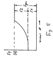
- the variation of the strand tension, which is exerted in this manner at the startup of the machine is represented in the diagram of Figure 5.
- the design of the brake clutch 17 results in a substantial consistency of the variation of the tension and the strand tension, which is exerted by the ballooning strand as a function of speed.
- Figure 6 of the drawings illustrates the known relationship between rotational speed and braking force for both an eddy-current brake and a hysteresis brake.
- the braking force of the eddy-current brake increases with the rotational speed, and with the force being smaller in the case of a large air gap between the cooperating surfaces.
- the braking force depends only on the fact that there is relative movement between the cooperating surfaces and it is generally independent of rotational speed.
- the force is inversely related to the dimension of the air gap. This distinction is of importance since in a speed dependent brake the braking force is transformed into heat and the heat increases with speed, whereas in a brake which is independent of speed, the generation of heat is constant and can be kept at a low level.
Landscapes
- Engineering & Computer Science (AREA)
- General Engineering & Computer Science (AREA)
- Mechanical Engineering (AREA)
- Tension Adjustment In Filamentary Materials (AREA)
- Ropes Or Cables (AREA)
- Yarns And Mechanical Finishing Of Yarns Or Ropes (AREA)
- Braking Arrangements (AREA)
- Manipulator (AREA)
Applications Claiming Priority (6)
| Application Number | Priority Date | Filing Date | Title |
|---|---|---|---|
| DE4003086 | 1990-02-02 | ||
| DE4003086 | 1990-02-02 | ||
| DE4005073 | 1990-02-17 | ||
| DE4019585 | 1990-06-20 | ||
| DE4019585 | 1990-06-20 | ||
| DE4005073 | 1990-12-17 |
Publications (2)
| Publication Number | Publication Date |
|---|---|
| EP0440246A1 true EP0440246A1 (de) | 1991-08-07 |
| EP0440246B1 EP0440246B1 (de) | 1995-05-17 |
Family
ID=27200791
Family Applications (1)
| Application Number | Title | Priority Date | Filing Date |
|---|---|---|---|
| EP91101324A Expired - Lifetime EP0440246B1 (de) | 1990-02-02 | 1991-02-01 | Bremsvorrichtung für fadenförmiges Gut |
Country Status (7)
| Country | Link |
|---|---|
| US (1) | US5342000A (de) |
| EP (1) | EP0440246B1 (de) |
| KR (1) | KR910021550A (de) |
| AT (1) | ATE122642T1 (de) |
| CA (1) | CA2035417A1 (de) |
| DE (1) | DE69109699T2 (de) |
| RU (1) | RU2011451C1 (de) |
Cited By (4)
| Publication number | Priority date | Publication date | Assignee | Title |
|---|---|---|---|---|
| GB2281918A (en) * | 1993-09-21 | 1995-03-22 | Pillarhouse Int Ltd | Wire tensioner with hysteresis brake |
| EP2653428A1 (de) * | 2012-04-16 | 2013-10-23 | Fernsteuergeräte Kurt Oelsch GmbH | Seillängengeber |
| EP2813456A1 (de) | 2013-06-11 | 2014-12-17 | Rigas Tehniska universitate | Kabelbremse und Rückwärtsspannungsvorrichtung |
| CN104280681A (zh) * | 2013-07-12 | 2015-01-14 | 广东美的制冷设备有限公司 | 电机动态负载模拟系统 |
Families Citing this family (26)
| Publication number | Priority date | Publication date | Assignee | Title |
|---|---|---|---|---|
| US6431481B1 (en) * | 1997-08-29 | 2002-08-13 | General Electric Company | Systems, methods and apparatus for winding conductive wires for a stator of an electric motor |
| WO2007079264A2 (en) * | 2005-12-30 | 2007-07-12 | Overend Technologies, Llc | Unwind and feed system for elastomeric thread |
| US20110068208A1 (en) * | 2007-05-01 | 2011-03-24 | Us Government As Represented By The Secretary Of Army | Fiber tensioning device and method of making prestressed structures |
| US20080272221A1 (en) * | 2007-05-01 | 2008-11-06 | Emerson Ryan P | Fiber tensioning device |
| EP2757211B1 (de) * | 2008-05-19 | 2019-01-09 | Max Co., Ltd. | Drahtrollenbremssystem in einer Maschine zur Bindung von Bewehrungsstäben |
| NZ575464A (en) | 2009-03-10 | 2010-07-30 | Holmes Solutions Ltd | Improvements in and relating to braking mechanisms |
| SE534221C2 (sv) * | 2009-10-26 | 2011-06-07 | Ett drivsystem till en rengöringsanordning för tankrengöring och en rengöringsanordning för tankrengöring | |
| US9802787B2 (en) * | 2013-09-20 | 2017-10-31 | Reel Power Licensing Corp. | Method of providing a clutch for a spool |
| NZ619034A (en) | 2013-12-16 | 2015-03-27 | Eddy Current Ltd Partnership | An assembly to control relative speed of movement between parts |
| KR102449222B1 (ko) | 2014-08-18 | 2022-09-28 | 에디 커런트 리미티드 파트너쉽 | 부재들 사이의 운동학적 관계의 조정 |
| KR102284956B1 (ko) | 2014-08-18 | 2021-08-03 | 에디 커런트 리미티드 파트너쉽 | 부재들 사이의 운동학적 관계의 조정 |
| CN110838781B (zh) | 2014-08-18 | 2021-12-21 | 涡流有限合伙公司 | 闩锁设备 |
| EP3183039B1 (de) * | 2014-08-20 | 2021-03-10 | Trublue Llc | Wirbelstrombremsvorrichtung für rotierende systeme |
| KR102575004B1 (ko) | 2014-12-04 | 2023-09-04 | 에디 커런트 리미티드 파트너쉽 | 에너지 흡수 장치 |
| WO2016089226A1 (en) | 2014-12-04 | 2016-06-09 | Eddy Current Limited Partnership | Methods of altering eddy current interactions |
| WO2016089228A1 (en) | 2014-12-04 | 2016-06-09 | Eddy Current Limited Partnership | Eddy current brake configurations |
| AU2015355673B2 (en) | 2014-12-04 | 2020-04-30 | Surewerx Usa, Inc. | Transmissions incorporating eddy current braking |
| KR102405797B1 (ko) | 2014-12-04 | 2022-06-03 | 에디 커런트 리미티드 파트너쉽 | 요소들 사이에서의 래치 활성화 |
| BR122021013798B1 (pt) | 2015-12-18 | 2023-04-18 | Eddy Current Limited Partnership | Mecanismo de controle de funcionamento variável para sistema motriz |
| CN106948197B (zh) * | 2017-04-01 | 2023-01-03 | 东台磊达钢帘线有限公司 | 一种帘线成型控制装置 |
| WO2020035801A1 (de) * | 2018-08-17 | 2020-02-20 | Schleuniger Holding Ag | Vorrichtung und verfahren zum bremsen eines leiters |
| RS67252B1 (sr) * | 2019-05-20 | 2025-10-31 | Schleuniger Ag | Postupak za kočenje najmanje jednog obrtnog valjka uređaja za ispravljanje, mašine za obradu kablova sa uređajem za ispravljanje |
| EP4031254B1 (de) | 2019-09-20 | 2025-07-09 | Trublue LLC | Abschaltbare abstiegskontrollsysteme und -vorrichtungen |
| CN115348886B (zh) | 2020-03-18 | 2024-10-15 | 特鲁布鲁有限公司 | 线分配装置 |
| CN114289250A (zh) * | 2021-12-14 | 2022-04-08 | 泰州科聚新材料技术研究院有限公司 | 一种感光材料板涂覆感光材料装置 |
| US20240239628A1 (en) * | 2023-01-18 | 2024-07-18 | Reel Power Licensing Corp. | Constant tension coiler with electromagnetic brakes |
Citations (6)
| Publication number | Priority date | Publication date | Assignee | Title |
|---|---|---|---|---|
| CH545743A (en) * | 1972-06-07 | 1974-02-15 | Eddy current yarn brake - including centrifugal clutch in friction contact with central bolt | |
| US3830050A (en) * | 1971-06-25 | 1974-08-20 | Hamana Iron Works Co | Wire stranding machine |
| DE2808470A1 (de) * | 1978-02-28 | 1979-08-30 | Erich Brosa | Fadenbremse und -zugkraftmesser |
| GB2117015A (en) * | 1981-12-01 | 1983-10-05 | Mackie And Sons Limited James | Tension control in yarn winding or spooling machines |
| GB2137237A (en) * | 1983-03-29 | 1984-10-03 | Tanac Eng Kk | Tensioning running wire |
| US4516739A (en) * | 1984-03-30 | 1985-05-14 | At&T Technologies, Inc. | Magnetically controlled wire tensioning device |
Family Cites Families (11)
| Publication number | Priority date | Publication date | Assignee | Title |
|---|---|---|---|---|
| US2519882A (en) * | 1948-04-30 | 1950-08-22 | Gen Electric | Constant torque device |
| US2705362A (en) * | 1950-06-03 | 1955-04-05 | Celanese Corp | Apparatus for winding yarn |
| US2839697A (en) * | 1953-12-08 | 1958-06-17 | Warner Electric Brake & Clutch | Magnetic torque producing device |
| US3042327A (en) * | 1958-01-10 | 1962-07-03 | Us Rubber Co | Quill winder |
| US3259336A (en) * | 1964-04-08 | 1966-07-05 | Automation Machines & Equipmen | Coil winding machine |
| DE2404030A1 (de) * | 1974-01-29 | 1975-08-14 | Barmag Barmer Maschf | Verseilmaschine |
| SU860712A1 (ru) * | 1974-02-16 | 1981-08-30 | Бармаг Бармер Машиненфабрик Аг (Фирма) | Канатовьюща машина |
| DE2812100C2 (de) * | 1978-03-20 | 1987-04-16 | Barmag Barmer Maschinenfabrik Ag, 5630 Remscheid | Verfahren zum Führen eines aus Einzelsträngen zusammengesetzten Gesamtstranges und Herstellen von gefachten Drahtspulen sowie Vorrichtung zum Durchführen des Verfahrens |
| DE2848384A1 (de) * | 1978-11-08 | 1980-05-22 | Barmag Barmer Maschf | Verseil- oder zwirnmaschine fuer draht |
| DE3531680A1 (de) * | 1984-09-13 | 1986-04-24 | Barmag Barmer Maschinenfabrik Ag, 5630 Remscheid | Stahlkordseil sowie verfahren und vorrichtung zu seiner herstellung |
| DE4005739A1 (de) * | 1989-03-03 | 1990-09-06 | Barmag Barmer Maschf | Drehbare ablaufspule |
-
1991
- 1991-01-28 KR KR1019910001380A patent/KR910021550A/ko not_active Ceased
- 1991-01-30 US US07/647,806 patent/US5342000A/en not_active Expired - Fee Related
- 1991-01-31 CA CA002035417A patent/CA2035417A1/en not_active Abandoned
- 1991-02-01 AT AT91101324T patent/ATE122642T1/de not_active IP Right Cessation
- 1991-02-01 DE DE69109699T patent/DE69109699T2/de not_active Expired - Fee Related
- 1991-02-01 EP EP91101324A patent/EP0440246B1/de not_active Expired - Lifetime
- 1991-02-01 RU SU914894377A patent/RU2011451C1/ru active
Patent Citations (6)
| Publication number | Priority date | Publication date | Assignee | Title |
|---|---|---|---|---|
| US3830050A (en) * | 1971-06-25 | 1974-08-20 | Hamana Iron Works Co | Wire stranding machine |
| CH545743A (en) * | 1972-06-07 | 1974-02-15 | Eddy current yarn brake - including centrifugal clutch in friction contact with central bolt | |
| DE2808470A1 (de) * | 1978-02-28 | 1979-08-30 | Erich Brosa | Fadenbremse und -zugkraftmesser |
| GB2117015A (en) * | 1981-12-01 | 1983-10-05 | Mackie And Sons Limited James | Tension control in yarn winding or spooling machines |
| GB2137237A (en) * | 1983-03-29 | 1984-10-03 | Tanac Eng Kk | Tensioning running wire |
| US4516739A (en) * | 1984-03-30 | 1985-05-14 | At&T Technologies, Inc. | Magnetically controlled wire tensioning device |
Cited By (6)
| Publication number | Priority date | Publication date | Assignee | Title |
|---|---|---|---|---|
| GB2281918A (en) * | 1993-09-21 | 1995-03-22 | Pillarhouse Int Ltd | Wire tensioner with hysteresis brake |
| EP0644146A3 (de) * | 1993-09-21 | 1995-07-19 | Pillarhouse Int Ltd | Spannvorrichtung. |
| EP2653428A1 (de) * | 2012-04-16 | 2013-10-23 | Fernsteuergeräte Kurt Oelsch GmbH | Seillängengeber |
| EP2653428B1 (de) | 2012-04-16 | 2015-09-30 | Fernsteuergeräte Kurt Oelsch GmbH | Seillängengeber |
| EP2813456A1 (de) | 2013-06-11 | 2014-12-17 | Rigas Tehniska universitate | Kabelbremse und Rückwärtsspannungsvorrichtung |
| CN104280681A (zh) * | 2013-07-12 | 2015-01-14 | 广东美的制冷设备有限公司 | 电机动态负载模拟系统 |
Also Published As
| Publication number | Publication date |
|---|---|
| EP0440246B1 (de) | 1995-05-17 |
| DE69109699D1 (de) | 1995-06-22 |
| CA2035417A1 (en) | 1991-08-03 |
| KR910021550A (ko) | 1991-12-20 |
| RU2011451C1 (ru) | 1994-04-30 |
| US5342000A (en) | 1994-08-30 |
| DE69109699T2 (de) | 1995-10-26 |
| ATE122642T1 (de) | 1995-06-15 |
Similar Documents
| Publication | Publication Date | Title |
|---|---|---|
| US5342000A (en) | Strand braking apparatus | |
| EP0225670B1 (de) | Verfahren und Vorrichtung zum Abwickeln eines Fadens von einer Garnspule in Webmaschinen | |
| US2586037A (en) | Uniform strand tension device | |
| JPS6350555A (ja) | 電子的糸張力制御機能を有する給糸装置 | |
| US4327873A (en) | Apparatus for regulating the speed of a member delivering or winding a yarn | |
| EP1045809B1 (de) | Selbstkompensierende vorrichtung zur regelung der spannung einer faser | |
| US4650133A (en) | Winder apparatus and method | |
| US4381852A (en) | Automatic tensioning control for winding stator coils | |
| US2741437A (en) | Constant tension take-up and let-off mechanism | |
| JPH09263359A (ja) | コード類の張力調整機構 | |
| US3982706A (en) | Winding machines having independent spindles | |
| US4137731A (en) | Thread supply device for textile machine having common thread control and tension sensing element | |
| US3063228A (en) | Apparatus for controlling the tensioning of the tapes in electric cable taping machines | |
| US4643368A (en) | Continuous spooler for and method of winding reels with selected length long ends | |
| JPH03206151A (ja) | 糸状材料を織機に給糸する装置 | |
| JPH04501695A (ja) | ロールブレーキ装置 | |
| US2929573A (en) | Compensating mechanism for taping machines and the like | |
| US3371879A (en) | Yarn winding apparatus | |
| US3837598A (en) | Wire tensioning apparatus | |
| US4491206A (en) | Braking device | |
| JPS6019666A (ja) | 定張力バネを用いた線の張力調整装置 | |
| US3138913A (en) | Winding or lapping machine | |
| SU749781A1 (ru) | Устройство дл подачи нити | |
| GB2117015A (en) | Tension control in yarn winding or spooling machines | |
| RU2260555C1 (ru) | Устройство для размотки длинномерного материала |
Legal Events
| Date | Code | Title | Description |
|---|---|---|---|
| PUAI | Public reference made under article 153(3) epc to a published international application that has entered the european phase |
Free format text: ORIGINAL CODE: 0009012 |
|
| AK | Designated contracting states |
Kind code of ref document: A1 Designated state(s): AT DE FR GB IT |
|
| 17P | Request for examination filed |
Effective date: 19910704 |
|
| 17Q | First examination report despatched |
Effective date: 19930406 |
|
| ITF | It: translation for a ep patent filed | ||
| GRAA | (expected) grant |
Free format text: ORIGINAL CODE: 0009210 |
|
| AK | Designated contracting states |
Kind code of ref document: B1 Designated state(s): AT DE FR GB IT |
|
| REF | Corresponds to: |
Ref document number: 122642 Country of ref document: AT Date of ref document: 19950615 Kind code of ref document: T |
|
| ET | Fr: translation filed | ||
| REF | Corresponds to: |
Ref document number: 69109699 Country of ref document: DE Date of ref document: 19950622 |
|
| PG25 | Lapsed in a contracting state [announced via postgrant information from national office to epo] |
Ref country code: GB Effective date: 19960201 Ref country code: AT Effective date: 19960201 |
|
| PLBE | No opposition filed within time limit |
Free format text: ORIGINAL CODE: 0009261 |
|
| STAA | Information on the status of an ep patent application or granted ep patent |
Free format text: STATUS: NO OPPOSITION FILED WITHIN TIME LIMIT |
|
| 26N | No opposition filed | ||
| GBPC | Gb: european patent ceased through non-payment of renewal fee |
Effective date: 19960201 |
|
| PG25 | Lapsed in a contracting state [announced via postgrant information from national office to epo] |
Ref country code: FR Effective date: 19961031 |
|
| PG25 | Lapsed in a contracting state [announced via postgrant information from national office to epo] |
Ref country code: DE Effective date: 19961101 |
|
| REG | Reference to a national code |
Ref country code: FR Ref legal event code: ST |
|
| PG25 | Lapsed in a contracting state [announced via postgrant information from national office to epo] |
Ref country code: IT Free format text: LAPSE BECAUSE OF NON-PAYMENT OF DUE FEES Effective date: 20050201 |