EP0441132B1 - Apparatus for manufacturing magnetic recording medium - Google Patents
Apparatus for manufacturing magnetic recording medium Download PDFInfo
- Publication number
- EP0441132B1 EP0441132B1 EP91100418A EP91100418A EP0441132B1 EP 0441132 B1 EP0441132 B1 EP 0441132B1 EP 91100418 A EP91100418 A EP 91100418A EP 91100418 A EP91100418 A EP 91100418A EP 0441132 B1 EP0441132 B1 EP 0441132B1
- Authority
- EP
- European Patent Office
- Prior art keywords
- roll
- carrier
- tape
- baffle plate
- ozone
- Prior art date
- Legal status (The legal status is an assumption and is not a legal conclusion. Google has not performed a legal analysis and makes no representation as to the accuracy of the status listed.)
- Expired - Lifetime
Links
- 230000005291 magnetic effect Effects 0.000 title claims description 76
- 238000004519 manufacturing process Methods 0.000 title claims description 13
- CBENFWSGALASAD-UHFFFAOYSA-N Ozone Chemical compound [O-][O+]=O CBENFWSGALASAD-UHFFFAOYSA-N 0.000 claims description 48
- 238000010438 heat treatment Methods 0.000 claims description 29
- QVGXLLKOCUKJST-UHFFFAOYSA-N atomic oxygen Chemical compound [O] QVGXLLKOCUKJST-UHFFFAOYSA-N 0.000 claims description 17
- 239000001301 oxygen Substances 0.000 claims description 17
- 229910052760 oxygen Inorganic materials 0.000 claims description 17
- 230000001590 oxidative effect Effects 0.000 claims description 10
- 230000002093 peripheral effect Effects 0.000 claims description 9
- 238000011144 upstream manufacturing Methods 0.000 claims description 6
- 238000001816 cooling Methods 0.000 claims description 5
- 238000007664 blowing Methods 0.000 claims description 2
- 238000005192 partition Methods 0.000 claims description 2
- 239000010410 layer Substances 0.000 description 37
- 239000007789 gas Substances 0.000 description 28
- 238000007254 oxidation reaction Methods 0.000 description 8
- 239000010408 film Substances 0.000 description 5
- 239000002184 metal Substances 0.000 description 5
- 229910052751 metal Inorganic materials 0.000 description 5
- 230000005294 ferromagnetic effect Effects 0.000 description 4
- 238000000034 method Methods 0.000 description 4
- 230000004308 accommodation Effects 0.000 description 3
- 238000002207 thermal evaporation Methods 0.000 description 3
- XEEYBQQBJWHFJM-UHFFFAOYSA-N Iron Chemical compound [Fe] XEEYBQQBJWHFJM-UHFFFAOYSA-N 0.000 description 2
- PXHVJJICTQNCMI-UHFFFAOYSA-N Nickel Chemical compound [Ni] PXHVJJICTQNCMI-UHFFFAOYSA-N 0.000 description 2
- 230000007797 corrosion Effects 0.000 description 2
- 238000005260 corrosion Methods 0.000 description 2
- 238000007733 ion plating Methods 0.000 description 2
- 238000003672 processing method Methods 0.000 description 2
- 239000010409 thin film Substances 0.000 description 2
- MYMOFIZGZYHOMD-UHFFFAOYSA-N Dioxygen Chemical compound O=O MYMOFIZGZYHOMD-UHFFFAOYSA-N 0.000 description 1
- 239000000956 alloy Substances 0.000 description 1
- 229910045601 alloy Inorganic materials 0.000 description 1
- 229910017052 cobalt Inorganic materials 0.000 description 1
- 239000010941 cobalt Substances 0.000 description 1
- GUTLYIVDDKVIGB-UHFFFAOYSA-N cobalt atom Chemical compound [Co] GUTLYIVDDKVIGB-UHFFFAOYSA-N 0.000 description 1
- 229910001882 dioxygen Inorganic materials 0.000 description 1
- 238000009826 distribution Methods 0.000 description 1
- 238000004299 exfoliation Methods 0.000 description 1
- 229910052742 iron Inorganic materials 0.000 description 1
- 150000002739 metals Chemical class 0.000 description 1
- 229910052759 nickel Inorganic materials 0.000 description 1
- 239000002985 plastic film Substances 0.000 description 1
- 239000011241 protective layer Substances 0.000 description 1
- 238000004544 sputter deposition Methods 0.000 description 1
Images


Classifications
-
- G—PHYSICS
- G11—INFORMATION STORAGE
- G11B—INFORMATION STORAGE BASED ON RELATIVE MOVEMENT BETWEEN RECORD CARRIER AND TRANSDUCER
- G11B5/00—Recording by magnetisation or demagnetisation of a record carrier; Reproducing by magnetic means; Record carriers therefor
- G11B5/84—Processes or apparatus specially adapted for manufacturing record carriers
- G11B5/8408—Processes or apparatus specially adapted for manufacturing record carriers protecting the magnetic layer
Definitions
- the present invention relates to an apparatus for manufacturing a magnetic recording medium, and more particularly relates to a device for manufacturing a magnetic recording medium through the oxidization of the surface of a thin magnetic film formed by ion plating, evaporative deposition or the like.
- a magnetic recording medium formed of a thin film of a ferromagnetic metal directly deposited on a carrier by utilizing the methods of vacuum evaporative deposition, sputtering, ion plating or the like has recently been used to meet the demand for higher recording density in magnetic recording media.
- the magnetic recording medium of the thin ferromagnetic metal film type has a number of advantages in terms of magnetic properties, it has the disadvantages that the thin film constituting the magnetic recording layer of the medium is very likely to he oxidized and is likely to undergo exfoliation from the carrier or other damage due to contact with the recording/playback magnetic head during recording or playback.
- proposals have been made to provide various protective layers on the surfaces of such thin ferromagnetic metal films.
- a method of manufacturing a magnetic recording medium in which a magnetic recording layer is formed of a ferromagnetic metal such as iron, nickel and cobalt or an alloy of such metals on a plastic sheet carrier by evaporative deposition method or the like has been widely used.
- gaseous oxygen or ozone is blown against the magnetic recording layer, or the layer is exposed to an atmosphere of oxygen or ozone to oxidize the surface of the layer so as to maintain the electromagnetic converting property, durability and corrosion resistance of the medium for a long period of time.
- Such an apparatus is disclosed, for instance, in US 46 43 915, Japanese Unexamined Published Patent Applications Nos. 26319/83 and 63031/84, and Japanese Patent Application No. 21534/89.
- the apparatus disclosed in US 46 43 915 for manufacturing a magnetic recording medium includes a device having a hermetic chamber for oxidizing the surface of a thin magnetic film formed on a flexible carrier.
- the hermetic chamber contains a supply roll of the carrier, a rotatable processing roll accommodated in a processing chamber, a take-up roll of the carrier, guide means for guiding the carrier from the supply roll into the processing chamber and through a predetermined angle along the surface of the processing roll and then to the take-up roll, and a nozzle unit provided near the surface of the processing roll whereon the carrier is wound for blowing gaseous oxygen or ozone towards the thin magnetic film on the carrier.
- the magnetic recording layer can be oxidized immediately after being deposited on the carrier.
- the conditions for oxidization are restricted by the conditions which must be maintained for forming the layer itself.
- the efficiency of oxidization is very low, that is, the speed of the oxidization cannot be increased. This is a problem.
- the productivity of the method is so low as to not be acceptable for practical industrial use. This is also a problem.
- the present invention was made in order to solve the above-discussed problems. Accordingly, it is an object of the invention to provide an apparatus for manufacturing a magnetic recording medium which is capable of achieving high productivity due to very efficient oxidization of the magnetic layer of the medium so as to ensure that the electromagnetic converting property, durability and corrosion resistance of the magnetic layer are maintained for a long period of time.
- the present invention achieves its object by providing an apparatus comprising the features set out in claim 1.
- an apparatus for manufacturing a magnetic recording medium which incorporates a device which oxidizes the magnetic layer of the magnetic recording medium after the layer is deposited on a flexible carrier in manufacturing the medium, which device is characterized in that the carrier already provided with the layer is continuously unwound from a supply roll in a hermetic chamber, then wound through a prescribed angle on a rotatable heating roll, and then wound on a take-up roll, a baffle plate is provided near the peripheral surface of the portion of the heating roll on which the carrier is wound, and gaseous oxygen or ozone is blown against the layer from nozzles provided inside the baffle plate.
- Fig. 1 shows a device 1 for oxidizing the magnetic layer of a magnetic tape T in manufacturing the tape, and constitutes a first preferred embodiment of the invention.
- the device 1 basically includes a hermetic chamber 10 including a processing chamber 3 provided with a heating roll 2, and two tape roll accommodation chambers adjacent the processing chamber and located on mutually opposite sides thereof.
- One of the tape roll accommodation chambers is a roll loading chamber 18 in which a supply roll 21 is accommodated.
- the other of the tape roll accommodation chambers is a roll takeout chamber 19, from which a completed wound roller 22 is removed.
- the roll loading chamber 18 is provided with a hermetic door 26, which is opened when the unwound roll 21 of the magnetic tape T is put into the chamber before the tape is subjected to oxidization.
- the roll takeout chamber 19 is provided with a hermetic door 27, which is opened when the wound roll 22 of the magnetic tape T is taken out from the chamber after the tape is subjected to the oxidization.
- a preheating roll 14 for preheating the magnetic tape T and guiding the movement thereof is provided in the passage for the tape upstream of the heating roll 2 with regard to the direction of movement of the tape.
- a cooling roll 17 for cooling the magnetic tape T to an appropriate temperature of about 10 to 50°C before the tape is wound on the wound roll 22 is provided in the passage of the tape downstream of the heating roll 2 with regard to the direction of movement of the tape.
- the device further includes a gas discharge system 15 for maintaining the pressure or concentration of gas in the hermetic chamber 10 at a desired level.
- the system is also provided with an ozone decomposer 16 for preventing problems from arising due to the leakage of ozone gas.
- Air can be supplied into the roll takeout chamber 19 to make the pressure of the air therein higher than that in the processing chamber 3 to prevent the ozone gas from entering the roll takeout chamber 19 and over-oxidizing the magnetic layer of the tape T wound on the wound roll 22 therein, thus ensuring that the quality of tape is uniformly good.
- the ozone is produced by an ozone generator 15, and is then injected into the chamber 3 through pipes 12 and two ejection nozzle units 8.
- a baffle plate 4 whose width is not less than that of the magnetic tape T is provided in the processing chamber 3, extending along the tape portion wound on the heating roll 2.
- the distance between the baffle plate 4 and the peripheral surface of the heating roll 2 is not confined to a particular value, but may be set at 2 to 30 mm, for example.
- the ozone ejection nozzle units 8 are provided inside the baffle plate 4, and located at an appropriate distance from each other.
- One of the nozzle units 8 is located at the upstream end portion of the baffle plate 4 with regard to the direction of movement of the magnetic tape T, and the other of the units is located at the middle portion of the plate so that the ozone gas supplied from the nozzle units accompanies the tape sufficiently.
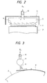
- Each of the nozzle units 8 includes a cylindrical body 11 extending rightward and leftward from the tip of the pipe 12 along the width of the magnetic tape T, and a plurality of nozzles 9 provided at equal intervals in the body and directed toward the magnetic layer of the tape, as shown in Fig. 2.
- the diameter of the heating roll 2, the length of the baffle plate 4, the width of the magnetic tape T, the speed of the movement of the tape, the concentration of the ozone gas on the tape, the flow rate of the ozone gas and the temperature of the heating of the magnetic layer of the tape are 1,000 mm, 2,000 mm, 300 mm, 0.5 to 15 m/min, 20 to 150 g/m3, 1 to 15 l/min and the room temperature to 140°C, respectively, for oxidizing the magnetic layer with the ozone gas
- the distance between the tape and the nozzles 9, the distance between the nozzles and the diameter of each of the nozzles may be set at 5 mm or less, 5 mm or less, and 1 mm or less, respectively, so that the magnetic layer is uniformly oxidized with the ozone gas.
- the direction of ejection of the ozone gas from each of the nozzles 9 toward the surface of the magnetic layer of the tape T not be perpendicular to that of the movement of the tape, but that the angle ⁇ between the direction of the ejection of the ozone gas and the perpendicular to the surface of the magnetic layer is more than 0°, as shown in Fig. 3.
- the ozone gas is very likely to accompany the tape T, and the impact of the ozone gas on the magnetic layer of the tape is low, even if the speed of ejection of the ozone gas from the nozzle 9 is high.
- the concentration of ozone gas on the tape is prevented from dropping too much while accompanying the moving tape on the heating roll 2.
- the plurality of nozzles 9 are juxtaposed along the entire width of the magnetic tape T, the ozone gas is not only uniformly blown against the entire surface of the magnetic layer of the tape, but also air accompanied with the moving tape is prevented from being involved and accompanying the moving tape on the heating roll 2.
- the baffle plate 4 Since the baffle plate 4 is provided near the peripheral surface of the portion of the heating roll 2 which the carrier of the tape T contacts, the ozone gas supplied from the nozzles 9 is somewhat enclosed between the baffle plate and the peripheral surface of the heating roll so that the concentration of ozone gas on the tape is maintained sufficiently high, even if the supplied quantity of the ozone gas is low. For this reason, the concentration of ozone gas in the whole of the processing chamber 3 need not be high. The surface of the magnetic layer of the tape T is thus oxidized with the ozone gas very efficiently. Moreover, significant losses of the heat of the heating roll 2 are prevented.
- the temperature of the heating roll 2 can be appropriately set so as to remove such a warp from the magnetic tape T while simultaneously oxidizing the surface of the magnetic layer thereof.
- the number of the ejection nozzle units 8 is not confined to two, but may be more than two. Also, oxygen gas may be used instead of ozone gas.
- baffle plate 4 and the ejection nozzle units 8 are provided separately from each other in the embodiment described above, the present invention is not confined to such an arrangement, and may be otherwise embodied as will now be described with reference to Fig. 4.
- a baffle plate 40 is made of a hollow plate having a large number of nozzles 41 in the whole side of the plate which faces a heating roll 2, as shown in Fig. 4. Ozone gas is ejected from the nozzles 41 toward a magnetic tape T.
- the interior of the baffle plate 40 is divided into two sections by a partition plate 42. Pipes 12 are connected to the sections. The size of each of the nozzles 41 may be altered depending on the position of the nozzle in consideration of the position of the connected portion of the pipe 12 for the nozzle, the distribution of the pressure of the ozone gas, and so forth.
- each of the nozzles 9 and 41 is not confined to being circularly shaped, but may be shaped as a slot.
- the present invention may be yet otherwise embodied so that a baffle plate 40 is bent at both side edge portions 51 thereof and has both its side edges 52 located in the grooves 20a of the sides of a heating roll 2, as shown in Fig. 5, to very much heighten the degree of the closure of an oxidization space defined by the baffle plate and the heating roll.
- the device provided in accordance with the present invention for oxidizing the magnetic layer of a magnetic recording medium after the layer is deposited on a flexible carrier in manufacturing the medium is characterized in that the carrier already provided with the magnetic layer is continuously unwound from an supply roll in a hermetic chamber, then wound through a prescribed angle on a rotatable heating roll, and then wound on a wound roll, a baffle plate is provided near the peripheral surface of the portion of the heating roll on which the carrier is wound, and gaseous oxygen or ozone is blown toward the magnetic layer from ejection nozzles provided inside the baffle plate.
- the baffle plate is provided near the peripheral surface of the portion of the heating roll with which the carrier of the medium is brought into contact, the gaseous oxygen or ozone is uniformly blown against the entire surface of the magnetic layer. Since the gaseous oxygen or ozone supplied from the ejection nozzles is somewhat enclosed between the baffle plate and the peripheral surface of the heating roll so as to maintain the concentration of the gaseous oxygen or ozone on the magnetic layer of the medium sufficiently high even if the supplied quantity of the gaseous oxygen or ozone is low, the concentration thereof in the whole of the hermetic chamber does not need to be high. For this reason, the magnetic layer can be oxidized with the gaseous oxygen or ozone very efficiently. Also, the heat of the heating roll is prevented from being lost, and the temperature of the heating roll can be set so as to remove the warp of the carrier while simultaneously oxidizing the magnetic layer with the gaseous oxygen or ozone.
Landscapes
- Manufacturing Of Magnetic Record Carriers (AREA)
Applications Claiming Priority (2)
| Application Number | Priority Date | Filing Date | Title |
|---|---|---|---|
| JP2004475A JPH03212819A (ja) | 1990-01-16 | 1990-01-16 | 磁気記録媒体の製造装置 |
| JP4475/90 | 1990-01-16 |
Publications (3)
| Publication Number | Publication Date |
|---|---|
| EP0441132A2 EP0441132A2 (en) | 1991-08-14 |
| EP0441132A3 EP0441132A3 (en) | 1991-12-04 |
| EP0441132B1 true EP0441132B1 (en) | 1995-11-15 |
Family
ID=11585140
Family Applications (1)
| Application Number | Title | Priority Date | Filing Date |
|---|---|---|---|
| EP91100418A Expired - Lifetime EP0441132B1 (en) | 1990-01-16 | 1991-01-15 | Apparatus for manufacturing magnetic recording medium |
Country Status (4)
| Country | Link |
|---|---|
| US (1) | US5123376A (ja) |
| EP (1) | EP0441132B1 (ja) |
| JP (1) | JPH03212819A (ja) |
| DE (1) | DE69114529T2 (ja) |
Families Citing this family (5)
| Publication number | Priority date | Publication date | Assignee | Title |
|---|---|---|---|---|
| US6835523B1 (en) | 1993-05-09 | 2004-12-28 | Semiconductor Energy Laboratory Co., Ltd. | Apparatus for fabricating coating and method of fabricating the coating |
| US5932302A (en) * | 1993-07-20 | 1999-08-03 | Semiconductor Energy Laboratory Co., Ltd. | Method for fabricating with ultrasonic vibration a carbon coating |
| US5803976A (en) * | 1993-11-09 | 1998-09-08 | Imperial Chemical Industries Plc | Vacuum web coating |
| US6156122A (en) * | 1999-06-30 | 2000-12-05 | Winbond Electronics Corp. | Depositor for depositing a dielectric layer with fewer metallic impurities and a method for reducing the content of the metallic impurities in the dielectric layer by using this depositor |
| JP5244380B2 (ja) * | 2007-12-26 | 2013-07-24 | 昭和電工株式会社 | 磁気記録媒体の製造方法及び磁気記録再生装置 |
Family Cites Families (3)
| Publication number | Priority date | Publication date | Assignee | Title |
|---|---|---|---|---|
| US3296014A (en) * | 1964-03-04 | 1967-01-03 | Robert C Williams | Method and apparatus for pressure cast coating |
| JPS5963031A (ja) * | 1982-10-04 | 1984-04-10 | Matsushita Electric Ind Co Ltd | 磁気記録媒体の製造方法 |
| JPS6111936A (ja) * | 1984-06-28 | 1986-01-20 | Fuji Photo Film Co Ltd | 磁気記録媒体の製造方法 |
-
1990
- 1990-01-16 JP JP2004475A patent/JPH03212819A/ja active Pending
-
1991
- 1991-01-15 DE DE69114529T patent/DE69114529T2/de not_active Expired - Fee Related
- 1991-01-15 EP EP91100418A patent/EP0441132B1/en not_active Expired - Lifetime
- 1991-01-15 US US07/641,399 patent/US5123376A/en not_active Expired - Lifetime
Also Published As
| Publication number | Publication date |
|---|---|
| EP0441132A2 (en) | 1991-08-14 |
| DE69114529T2 (de) | 1996-04-04 |
| DE69114529D1 (de) | 1995-12-21 |
| EP0441132A3 (en) | 1991-12-04 |
| US5123376A (en) | 1992-06-23 |
| JPH03212819A (ja) | 1991-09-18 |
Similar Documents
| Publication | Publication Date | Title |
|---|---|---|
| US4521482A (en) | Magnetic recording medium | |
| EP0441132B1 (en) | Apparatus for manufacturing magnetic recording medium | |
| US4450186A (en) | Method and device for manufacturing magnetic recording medium | |
| EP0935011A1 (en) | Method for forming film by plasma polymerization and apparatus for forming film by plasma polymerization | |
| US4935605A (en) | Apparatus for correcting curl of magnetic recording medium | |
| KR910007760B1 (ko) | 수직자기기록매체의 제조방법 | |
| US20050132960A1 (en) | Small volume environmental chamber and multi-chamber processing apparatus comprising same | |
| JPS58220244A (ja) | 磁気記録媒体及びその製造方法 | |
| US6238730B1 (en) | Gas introduction pipe and magnetic recording medium production method using the pipe | |
| JPS6217176A (ja) | 薄膜形成装置 | |
| JP3358352B2 (ja) | 成膜装置 | |
| JP3465354B2 (ja) | 薄膜形成装置 | |
| JPH0337826A (ja) | 磁気記録媒体の製造方法 | |
| JPH0765368A (ja) | 磁気記録媒体の製造装置 | |
| JPH10298758A (ja) | 薄膜製造方法及び装置 | |
| JPH10310869A (ja) | 磁気記録媒体の製造方法及び磁気記録媒体の製造装置 | |
| JPH01243234A (ja) | 磁気記録媒体の製造方法 | |
| JPH04281215A (ja) | 蒸着膜処理方法及び装置 | |
| JPH07331438A (ja) | 金属膜体の製造装置 | |
| JPH02220224A (ja) | 磁気記録媒体の製造方法 | |
| JPH0973758A (ja) | テープカセット | |
| JPS5888834A (ja) | 磁気記録媒体の製造方法 | |
| JPS60147932A (ja) | 磁気記録媒体製造装置 | |
| JPH0430644B2 (ja) | ||
| JPH11102519A (ja) | 磁気記録媒体の製造装置及び製造方法 |
Legal Events
| Date | Code | Title | Description |
|---|---|---|---|
| PUAI | Public reference made under article 153(3) epc to a published international application that has entered the european phase |
Free format text: ORIGINAL CODE: 0009012 |
|
| AK | Designated contracting states |
Kind code of ref document: A2 Designated state(s): DE NL |
|
| PUAL | Search report despatched |
Free format text: ORIGINAL CODE: 0009013 |
|
| AK | Designated contracting states |
Kind code of ref document: A3 Designated state(s): DE NL |
|
| 17P | Request for examination filed |
Effective date: 19920218 |
|
| 17Q | First examination report despatched |
Effective date: 19940607 |
|
| GRAA | (expected) grant |
Free format text: ORIGINAL CODE: 0009210 |
|
| AK | Designated contracting states |
Kind code of ref document: B1 Designated state(s): DE NL |
|
| PG25 | Lapsed in a contracting state [announced via postgrant information from national office to epo] |
Ref country code: NL Free format text: LAPSE BECAUSE OF FAILURE TO SUBMIT A TRANSLATION OF THE DESCRIPTION OR TO PAY THE FEE WITHIN THE PRESCRIBED TIME-LIMIT Effective date: 19951115 |
|
| REF | Corresponds to: |
Ref document number: 69114529 Country of ref document: DE Date of ref document: 19951221 |
|
| NLV1 | Nl: lapsed or annulled due to failure to fulfill the requirements of art. 29p and 29m of the patents act | ||
| PLBE | No opposition filed within time limit |
Free format text: ORIGINAL CODE: 0009261 |
|
| STAA | Information on the status of an ep patent application or granted ep patent |
Free format text: STATUS: NO OPPOSITION FILED WITHIN TIME LIMIT |
|
| 26N | No opposition filed | ||
| PGFP | Annual fee paid to national office [announced via postgrant information from national office to epo] |
Ref country code: DE Payment date: 20090108 Year of fee payment: 19 |
|
| PG25 | Lapsed in a contracting state [announced via postgrant information from national office to epo] |
Ref country code: DE Free format text: LAPSE BECAUSE OF NON-PAYMENT OF DUE FEES Effective date: 20100803 |