EP0443619A2 - Dispositif automatique à convoyer des documents - Google Patents
Dispositif automatique à convoyer des documents Download PDFInfo
- Publication number
- EP0443619A2 EP0443619A2 EP91102655A EP91102655A EP0443619A2 EP 0443619 A2 EP0443619 A2 EP 0443619A2 EP 91102655 A EP91102655 A EP 91102655A EP 91102655 A EP91102655 A EP 91102655A EP 0443619 A2 EP0443619 A2 EP 0443619A2
- Authority
- EP
- European Patent Office
- Prior art keywords
- document
- roller
- paper
- conveyed
- conveyor
- Prior art date
- Legal status (The legal status is an assumption and is not a legal conclusion. Google has not performed a legal analysis and makes no representation as to the accuracy of the status listed.)
- Withdrawn
Links
- 239000011521 glass Substances 0.000 claims abstract description 52
- 230000009471 action Effects 0.000 claims abstract description 18
- 238000011144 upstream manufacturing Methods 0.000 claims abstract description 9
- 230000033001 locomotion Effects 0.000 claims description 10
- 238000001514 detection method Methods 0.000 claims description 9
- 238000003825 pressing Methods 0.000 claims description 3
- 238000000034 method Methods 0.000 description 17
- 230000008569 process Effects 0.000 description 15
- 238000010586 diagram Methods 0.000 description 12
- 230000002265 prevention Effects 0.000 description 10
- 230000008859 change Effects 0.000 description 9
- 230000033228 biological regulation Effects 0.000 description 7
- 238000000926 separation method Methods 0.000 description 7
- 230000005540 biological transmission Effects 0.000 description 6
- 230000003287 optical effect Effects 0.000 description 5
- 230000002093 peripheral effect Effects 0.000 description 5
- 230000001360 synchronised effect Effects 0.000 description 5
- 230000006870 function Effects 0.000 description 2
- 238000004519 manufacturing process Methods 0.000 description 2
- 230000000063 preceeding effect Effects 0.000 description 2
- 230000001105 regulatory effect Effects 0.000 description 2
- 238000013459 approach Methods 0.000 description 1
- 230000001276 controlling effect Effects 0.000 description 1
- 230000000994 depressogenic effect Effects 0.000 description 1
- 230000006866 deterioration Effects 0.000 description 1
- 230000000694 effects Effects 0.000 description 1
- 238000005516 engineering process Methods 0.000 description 1
- 230000006872 improvement Effects 0.000 description 1
- 230000004044 response Effects 0.000 description 1
- 230000000087 stabilizing effect Effects 0.000 description 1
- 230000001629 suppression Effects 0.000 description 1
Images


Classifications
-
- G—PHYSICS
- G03—PHOTOGRAPHY; CINEMATOGRAPHY; ANALOGOUS TECHNIQUES USING WAVES OTHER THAN OPTICAL WAVES; ELECTROGRAPHY; HOLOGRAPHY
- G03G—ELECTROGRAPHY; ELECTROPHOTOGRAPHY; MAGNETOGRAPHY
- G03G15/00—Apparatus for electrographic processes using a charge pattern
- G03G15/60—Apparatus which relate to the handling of originals
-
- G—PHYSICS
- G03—PHOTOGRAPHY; CINEMATOGRAPHY; ANALOGOUS TECHNIQUES USING WAVES OTHER THAN OPTICAL WAVES; ELECTROGRAPHY; HOLOGRAPHY
- G03B—APPARATUS OR ARRANGEMENTS FOR TAKING PHOTOGRAPHS OR FOR PROJECTING OR VIEWING THEM; APPARATUS OR ARRANGEMENTS EMPLOYING ANALOGOUS TECHNIQUES USING WAVES OTHER THAN OPTICAL WAVES; ACCESSORIES THEREFOR
- G03B27/00—Photographic printing apparatus
- G03B27/32—Projection printing apparatus, e.g. enlarger, copying camera
- G03B27/52—Details
- G03B27/62—Holders for the original
- G03B27/6207—Holders for the original in copying cameras
- G03B27/625—Apparatus which relate to the handling of originals, e.g. presence detectors, inverters
- G03B27/6264—Arrangements for moving several originals one after the other to or through an exposure station
-
- G—PHYSICS
- G03—PHOTOGRAPHY; CINEMATOGRAPHY; ANALOGOUS TECHNIQUES USING WAVES OTHER THAN OPTICAL WAVES; ELECTROGRAPHY; HOLOGRAPHY
- G03G—ELECTROGRAPHY; ELECTROPHOTOGRAPHY; MAGNETOGRAPHY
- G03G2215/00—Apparatus for electrophotographic processes
- G03G2215/00172—Apparatus for electrophotographic processes relative to the original handling
- G03G2215/00177—Apparatus for electrophotographic processes relative to the original handling for scanning
- G03G2215/00181—Apparatus for electrophotographic processes relative to the original handling for scanning concerning the original's state of motion
- G03G2215/00185—Apparatus for electrophotographic processes relative to the original handling for scanning concerning the original's state of motion original at rest
Definitions
- the present invention relates to an improved automatic document conveying device for use with a recording device, an image read out device, or the like in an electrophotographic copying machine.
- Automatic document conveying devices are usually mounted on the document table glass (platen glass) of an image exposure section of a copying machine for use.
- documents in sheet form hereinafter, simply document
- a document loading table stacker section
- each document is discharged onto a document discharge table.
- the document conveying speed from the document double feed prevention position in the stack section to the document stop position on the glass surface of the document table must be high.
- Japanese Laid Open Patent Application 1-236136 provides a document conveying device with a short document change time.
- a special feature is that, when the first document is conveyed to a specified position and halted at that position, the second document is conveyed to and stopped at a position which is not upstream on the platen, separated from the specified position.
- the first document after the completion of the exposure process is at a position from which it can be conveyed conveyed by the conveying means to a downstream position on the platen separated from the specified position, at the same time, the second document is conveyed to a specified position and halted at that position. This procedure is repeated with the third and subsequent documents which are conveyed and halted in succession.
- this document conveying process has the drawback that three documents are conveyed simultaneously, so that the motor load increases, and a large current is necessary.
- the next document overtakes the preceeding document from the rear so that there is the possibility of damage occurring to the documents.
- the margin for jam detection is small and jam handling is also complicated.
- the gap between the rear end of the first document on the platen and the front end of the second document on the supply path is large, so the travel distance of the documents during document change increases, and accordingly, the time required for document change increases, which is a drawback.
- the front end of the next document is conveyed as far as the contact nip position between the conveyor belt on the platen glass and the platen glass itself and made to standby at that point.
- the contact position of the conveyor belt is determined by the position of a document presser roller which applies pressure to the conveyor belt on the platen glass surface from the underside of the pressure belt, and the front end of the document does not come close to the preceding document.
- a first object of the present invention is to provide, with due consideration to the drawbacks of such conventional devices, an improved automatic document conveying device wherein the number of documents copied is increased.
- an automatic document conveying device wherein one sheet at a time is separated from a stack of documents loaded on a document loading table and transported to a sequential image exposure section, the document is halted at the image exposure section, scanning and exposure are performed by a movingt optical system, then, after exposure the document is conveyed to a document discharge table.
- the automatic document conveying device of the present invention comprises a paper feed means which feeds the document to the image exposure section, a conveyor means which conveys each document to a specified position on the image exposure section and halts at that specified position, a paper discharge means which discharges the exposed document, and a control means for driving and controlling the other means.
- a first document from the loading table is conveyed by the conveyor means to a specified position on the image exposure section and halted, and while a specified number of copies are being scanned and exposed, the next document is conveyed to a position downstream from the document loading table and upstream from the document being scanned and exposed, and a standby action is completed.
- the discharge of the first document, on which scanning has been completed in the exposure section begins, and the second document, which is on standby, is conveyed to a specified position for exposure, then halted.
- the standby position is set at a position where the weight of the documents conveyed from the standby position to the specified exposure position is less than the conveyed weight of the scanned documents discharged at the specified position, then, at least before the first scanning and exposure is completed, the discharge of the first document in the process of being discharged is completed, and before the scanning of the set number of documents is completed, the third document is conveyed at the standby position.
- the automatic document conveying device of the present invention is provided with a detection means which determines the document size in the paper feed device. Based on a document size detection signal detected by the document detection means, the document is conveyed by the conveyor means to a specified position at the image exposure section. While the preceding document, on which the specified number of scanning and exposure operations has been carried out, is halted, the next document is conveyed to a specified standby position upstream from the previous document and put on standby. The pressing roller is driven, and the conveyor belt is controlled so that the conveyor belt is pressed against or moved away from the document table glass surface.
- a feature of the drive control of the pressure roller of the automatic document conveying device of the present invention is that the pressure roller is activated when the front end of the next document in the standby position for the image exposure section is selected on the conveyor downstream side from the pressure position of the pressure roller, and separation of the documents occurs in the direction where a large gap is created between the document table glass and the conveyor belt close to the pressure position.
- the automatic document conveying device of the present invention is constructed so that :
- FIG.1 configuration diagram illustrates an image forming device (for example, an electrophotographic copying machine) provided with an automatic document conveying device of the present invention.
- a main copying machine 100 comprises a scanning and exposure section A, an image forming section B, a paper feed section C, a conveyor section E, a fixing section F, a paper discharge section G, and a discharge paper tray H.
- the broken line in the drawing indicates the conveying path of a paper P.
- FIG.2 is a configuration diagram showing the document conveying path of the automatic document conveying device, which freely swings open and closed, on the upper surface of the main copying machine 100.
- FIG.3 is a configuration diagram showing a drive system (power transmission system) for the automatic document conveying device
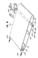
- FIG.4 a perspective view of the document conveying system and the drive system within the device
- FIG.5 a plan view of the main elements of the device.
- FIG.6A is a transverse view illustrating the document conveying process.
- the device illustrated in these drawings is an automatic document conveying device with a document reversing function (RADF).
- RADF document reversing function
- a document loading table 11 for loading stacks of documents is provided on the left side of the upper surface of a paper feed section 10 of the automatic document conveying device.
- a document set solenoid SD1 and a document front end stopper 12 which can be swung by means of the document set solenoid SD1 are provided on the lower side of the front end section of the document loading table 11.
- the upper end section of the stopper 12 projects close to the front end section of the document loading table 11.
- the stack of documents is loaded on the document loading table 11 and the front end section of the stack of documents contacts the document front end stopper 12 where the front ends of the papers are aligned.
- the presence of the documents on the document loading table is detected by a document set sensor (a sensor which determines when the number of documents is zero) PS2, and the ADF mode is indicated on the control panel on the main copying machine 100.
- a document set sensor a sensor which determines when the number of documents is zero
- a pair of width regulation plates 13, 13 for regulating the documents in the direction of their width is provided on the document loading table 11.
- the width regulation plates 13, 13 on the lower surface of the document loading table 11 are connected to a pair of rack gears 14B, 14B which can slide transversely in opposite directions, between which a pinion gear 14A is interposed, and the plates 13, 13 can be moved symmetrically with respect to the center.
- the rack gears 14B, 14B are connected to the respective width regulation plates 13, 13.
- the width of the document can be read out from the amount of movement determined by a size sensor PS1. From this read-out value, the length of a standard sized document D is automatically calculated. Accordingly, the stack of documents is loaded on the document loading table 11, and by sliding the width regulation plates 13, 13 to contact the sides of the documents, each type of document size, specifically, each manuscript length, can be recorded.
- a pick-up roller 15 is moved vertically by the action of a paper feed solenoid (latch-type) SD2 and spring pressure, and can be rotated by a drive motor M1.
- the automatic document conveying device is driven by operating the COPY button on the control panel of the copying machine 100, to apply power to the paper feed solenoid SD2.
- the pick-up roller 15 connected to the paper feed solenoid SD2 is caused to descend and press against the uppermost surface of the stack of documents, and at the same time the drive motor M1 starts and causes the documents to be sent forward.
- a paper feed separating means comprising a feed belt 17, which runs around a feed roller 16A and a follower roller 16B, and a double-feed prevention roller 18 positioned below the feed belt 17.
- the power from the drive motor M1 is transmitted to this paper feed separating means through a magnetic clutch K2, and one document only, - the document in the uppermost position among the many sheets of documents sent out from the pick-up roller 15 - is separated and sent forward.
- a document passage sensor PS3, a intermediate conveyor roller 25, and a curved guide plate 26 are provided on the document feed downstream side of the paper feed separating means.
- a document passage synchronizing sensor (reversed document passage sensor) PS5 positioned in the middle of the feed path generates a detection signal when the front end of the document passes, to control the conveying of the document.
- the document passage synchronized sensor PS5 controls the operation of a later discussed document stopper 102, the drive motor M1, the paper feed clutch K2, the conveyor clutch K1, and the like, through a clock timer.
- the document is interposed between a conveyor belt 31 which can move either forward or backward, and a document table glass for image exposure (hereinafter, document table glass) 101 on the upper surface of the main copying machine 100, and is conveyed in a conveying section 30.
- the document is halted by the action of a document stop solenoid (latch-type) SD3 at a position where its forward end section contacts a document stopper 102 projecting from the upper left end surface of the document table glass 101.
- the conveyor belt 31 passes over a conveyor belt drive roller 32, a follower roller 33, three document presser rollers 34A, 34B, 34C, and under a tension roller 35.
- the document D in the halt position on the document table glass 101 is exposed by means of a exposure lamp 103 in the main copying machine 100, and a document image is formed on a recording member by scanning with a scanning exposure section A comprising a lens, mirrors, and the like.
- the exposure is repeated in the same way with one sheet only of a set copy, and when the processing of a series of copies of the document is completed, the projecting section of the document stopper 102 is removed from the upper surface of the document table glass 101, to release the front end of the manuscript. Then, the conveyor belt 31 once again begins to move, along with a pair of discharge rollers 41, and the manuscript is discharged. The passage of the rear end of the document is detected by means of a document discharge sensor PS4, after which the document is discharged and loaded onto a discharge tray (document discharge table) 42.
- the automatic document conveying device is also provided with a document reversal section 50 for reversing turning the documents over on a document reversal path.
- a plurality of conveying rollers 51, 52, 53, a guide plate 54, and a reversed document passage sensor PS5 for detecting a document passing through the inside of the document reversal section 50 are positioned in the document reversal section 50.
- the drive motor M1 is an integrated servomotor comprising a DC motor and a speed control device (an encoder or a tachometer generator, or the like).
- a toothed belt B1 is fitted between a toothed pulley PI integrated with a drive shaft 20 of the drive motor M1 and a toothed pulley P2 secured to a countershaft 21, and rotated from the drive rotation of the motor M1.
- a pair of toothed pulleys P3, P4 and the magnetic clutch K1 are fitted to the countershaft 21.
- a toothed belt B2 runs between the toothed pulley P3 and a toothed pulley P5 secured on the end of the shaft of the conveyor belt drive roller 32.
- the follower roller 33 is rotated by the conveyor belt drive roller 32, via the conveyor belt 31.
- a toothed belt B3 which is engagingly positioned around the toothed pulley P4 provided on the countershaft 21, is also engagingly positioned around a toothed pulley P6 fitted onto a feed roller shaft 22 which rotates the feed roller 16A via a pair of gears G1, G2, and around an outer peripheral toothed section of a toothed pulley P7 fitted to a conveyor roller countershaft 23 which integrally comprises an intermediate conveyor roller 25.
- a pair of tension rollers R1, R2 are circumscribed and firmly contacted under tension by the outer peripheral surface of the toothed belt B3.
- the feed roller shaft 22 which is integrally combined with the toothed pulley P6, rotates the feed roller 16A via the gears G1, G2.
- the feed belt 17 which encloses the follower roller 16B moves, which causes the rotation of the pick-up roller 15 through the toothed pulleys P8, P9 and the toothed belt B4.
- the magnetic clutch K2 is mounted on the other end of the feed roller shaft 22 and is controlled through an input signal so that the feed belt 17 and the pick-up roller 15 rotate to feed the document.
- a paper discharge section 40 is provided on the conveyor downstream side of the follower roller 10.
- a paper discharge roller 41 is axially supported in a freely rotatable manner. Power is transmitted to the paper discharge roller 41 from a drive motor M2 through a plurality of gears G3, G4, G5.
- a follower roller 41A rotates from pressure applied by the paper discharge roller 41.
- the conveyor belt drive roller 32 begins to rotate in the counterclockwise direction so that the document is conveyed to the right on the document table glass 101 by the conveyor belt 31.
- the right side of the conveyed document is fed into the document reversal section 50.
- the document D in the document reversal section 50 follows the guide plate 54 and is interposedly maintained by the conveyor rollers 51, 52, 53 in sequence.
- the right end of the document D specifically the front end in this case, is discharged onto the document table glass 101.
- the front end of the document based on a signal from the reversed document passage sensor PS5, causes the conveyor belt drive roller 32 to be switched, to once again rotate in the clockwise direction.
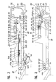
- FIG.6B, and FIG.6C are transverse views illustrating the document feed and conveying process
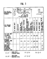
- FIG.7 is a view showing the rotational speed of each paper feed roller by means the drive system
- FIG.8 is a block diagram of the drive system
- FIG.9A and FIG.9b together show a time chart covering the automatic conveying of three documents. This process is completely under the control of a CPU.
- the drive systems for three operating systems - paper feed, conveying, and paper discharge - are operated and controlled with two motors, M1 and M2, and two magnetic clutches K1 and K2.
- M1 and M2 the drive systems for three operating systems - paper feed, conveying, and paper discharge - are operated and controlled with two motors, M1 and M2, and two magnetic clutches K1 and K2.
- M1 and M2 the drive systems for three operating systems - paper feed, conveying, and paper discharge - are operated and controlled with two motors, M1 and M2, and two magnetic clutches K1 and K2.
- M1 and M2 two motors
- K1 and K2 the drive systems for three operating systems - paper feed, conveying, and paper discharge -
- the document is turned over and returned to the document reversal section 50.
- the time commences from when the document is detected passing the reversed document passage sensor PS5.
- the feed start standby of the next document is controlled and carried out so that these copy modes are set for a large document which requires time in scanning and exposure, and in the case of multicopy mode.
- Both low speed paper feed and paper discharge are possible from CPU control.
- FIG.10 is a configuration diagram showing the conveying path of the document for the automatic document conveying device of the present invention.
- FIG.11 is an external perspective view of the automatic document conveying device mounted on a photocopying machine.
- FIG.12 is a configuration diagram showing the drive system (power transmission system) for the automatic document conveying device.
- FIG.13 is a transverse view of the overall drive system configuration of the device.
- FIG.14 is a transverse view of the conveying path of the document when both sides of the document are being copied.
- the device illustrated in these drawings is an automatic document conveying device with a document reversing function (RADF). The structure and operation of the automatic document conveying device will now be explained with reference to these drawings.
- RDF document reversing function
- the automatic document conveying device (RADF) of the present invention is installed on a main copying machine 201, as shown in FIG.10 and FIG.11, and comprises a paper feed section 210 from which one document from a document stack loaded on a document tray 211 is fed onto a document table glass 202; a conveyor section 220 which conveys the document supplied from the paper feed section 210 to a specified position (image scanning and exposure position) on the document table glass 202 on a document table; and a document discharge section 230 which discharges the document fed from the document conveyor section 220 after completion of the image exposure process, to a paper discharge tray 239.
- a paper feed section 210 from which one document from a document stack loaded on a document tray 211 is fed onto a document table glass 202
- a conveyor section 220 which conveys the document supplied from the paper feed section 210 to a specified position (image scanning and exposure position) on the document table glass 202 on a document table
- a document discharge section 230 which discharges the document fed from the document
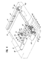
- a drive motor M is positioned in the center, while a feed section 210 on the right side, a conveyor section 220 in the center, and a document discharge section 230 on the left side of this drawing make up the drive system.
- the motor M as the drive source causes a pair of toothed pulleys P10, P11 to rotate, via a pair of gears G0, G6.
- Power for the paper feed section 210 and the document discharge section 230 is taken off by means of a toothed belt B6 and a toothed belt B7 respectively.
- the drive transmission system branching to the right of the drawings drives a feed roller 215B used for belt separation for the paper feed section 210, and an intermediate conveyor roller 218, as well as a drive roller 222 for a conveyor belt 221 in the conveyor section 220, via a gear train G7, G8, G9, G10, G11.
- a clutch K3 is built into a gear G11 fitted to the end of a shaft for the feed roller 215A. The clutch K3 is idle except during paper feed.
- the drive transmission system taken off to the left of the drawing via the belt B6 from the pulley P10 drives a paper discharge reversing roller 231 through a pair of pulleys P13, P14, and a pair of gears G12, G13.
- a unidirectional clutch K4 is provided on the gear G14, and a unidirectional clutch K5 is provided on the gear G12.
- the paper discharge reversing roller 231 and a paper discharge roller 235 are always unidirectionally rotated in the direction indicated by the arrows, unrelated to the direction in which the motor M is turning.
- the automatic document conveying device of the present invention shown in the transverse view, FIG.14 is capable of providing a two-sided copy, covering both sides of a document.
- the document D On completion of the customary one-sided copy passing through the same conveyor path, and of exposure and copying of the first side, the document D is conveyed along the path in the direction indicated by the arrows Z1, Z2. Then, without being discharged, the document D is turned over and conveyed via the paper discharge reversing roller 231 and a pair of pinch rollers 232, 233 along the reverse path in the direction indicated by the arrows Y1, Y2. The document D is then once again sent back to the document table glass 202 for exposure and copying of the second side (underside).
- the document D After exposure and copying, the document D once again is conveyed along the path in the direction indicated by the arrows Z1, Z2, and this time is discharged onto the discharge tray 239 by the discharge roller 235, via the paper discharge reversing roller 231 and the pinch rollers 232, 233, along the path indicated by the arrow Z3 as indicated in the drawing.
- the document loading table 211 on which stacks of documents can be loaded, is provided on the upper right of the surface of the paper feed section 210 of the automatic document conveying device.
- a solenoid SD3 On the front end downstream side of the document loading table 211, as shown in FIG.10, a solenoid SD3, a movable guide plate 212 which can be swung by means of the solenoid SD3, and a document front end stopper 213 are provided.
- the presence of the documents on the document loading table 211 is detected by a document set sensor (a sensor which determines when the number of documents is zero) PS6, and the RADF mode is indicated on the control panel on the main copying machine 201.
- a document set sensor a sensor which determines when the number of documents is zero
- a width regulation plate 214 for regulating the documents in the direction of their width is movably provided on the document loading table 211.
- a feed belt 216 On the document feed downstream side of the document loading table 211, a feed belt 216 is provided which encloses and causes a feed roller 215A and a follower roller 215B to rotate.
- a paper feed separation means comprising a double-feed prevention roller 217, is positioned below the feed belt 216. This paper feed separation means is driven by the motor M by power transmitted through the magnetic clutch K3.
- the automatic document conveying device is started by operating the COPY button on a control panel 203 of the copying machine 201 so that power is applied to the paper feed solenoid SD3.
- the front end of the movable guide plate 212 linked to the solenoid SD3 is dropped down to press the stack of documents to the surface of the feed belt 216.
- the documents are sent forward by the feed belt 216 which begins to move from the drive power provided by the drive motor M.
- the fixed double-feed prevention roller 217 ensures that only the uppermost sheet of the document D from the plurality of sheets in the stack is separated out and sent forward. At this time the double-feed prevention roller 217 prevent the underlayers which follow the first document sheet from advancing.
- a document passage sensor (document size sensor) PS7, an intermediate conveyor roller 218, and a pair of curved guide plates 219 are provided on the document feed downstream side of the paper feed separating means.
- the second clutch K4 is activated and the document D is conveyed to the nip of the intermediate conveyor roller 218.
- the first clutch K3 driving the feed roller 215A is deactivated and the feed belt 216 proceeds between the drive shaft and the unidirectional clutch engaging the feed roller 215A until the document D is cleared, then halts.
- the passage of the front end of the one sheet of the document fed out by the paper feed separating means is detected by the document passage sensor PS7, and when the sensor PS7 is activated a first timer TM1 begins counting.
- the document is fed by the adjacent pair of intermediate conveyor rollers 218, passes through the guide plates 219, and is fed toward the document table glass 202.
- the document D is interposedly conveyed between the document table glass 202 and a conveyor belt 221 which moves at almost the same speed as the peripheral speed of the intermediate conveyor rollers 218.
- the length of the document is determined by the detection of the passage of the rear end of the document by the sensor PS7.
- the sensor PS7 also detects paper jams in the paper feed section 210.
- the conveyor belt 221 passes around a conveyor belt drive roller 222, a follower roller 223, a pair of document presser rollers 224, 225, and a movable pressure roller 226 by which pressure can be applied or released.
- the conveyor belt 221 can be driven in the forward or the reverse direction by the motor M.
- the lower running surface of the conveyor belt 221 is pressed against the surface of the document table glass 202 by the document presser rollers 224, 225, and the movable pressure roller 226.
- the length of the document D is measured by the time taken from the passage of the front end of the document to the passage of the rear end of the document as detected by the sensor PS6.
- Three types of modes can be set from the ranges in the following three classifications.
- the front end of the document D5 contacts the document stopper 205 and halts.
- the movable pressure roller 226 is elevated from the position indicated by the broken line to the position indicated by the solid line in the drawing, by a solenoid which has been omitted from the drawing.
- the configuration of the conveyor belt 221 is changed from the configuration under tension as indicated by the broken line in FIG.15 to the state indicated by the solid line.
- the conveyor belt 221 between the document presser roller 225 and the movable pressure roller 226 is elevated, causing a gap to be created between the belt 221 and the document table glass 202.
- the follower roller 223 of the conveyor belt 221 is also externally placed under tension from the pressure from a spring 223a, and the slack in the conveyor belt 221 is taken up by the movement of the movable pressure roller 226.
- the document D5 in the halt position on the document table glass 202 is exposed by a exposure lamp 206 (see FIG.10) in the main copying machine 201, and a document image is formed on a recording member by scanning with a scanning exposure section comprising a lens, mirrors, and the like.
- the first clutch K3 and the second clutch K4 are activated, and the next document D6 is fed out.
- a second timer TM2 starts its count.
- the second timer TM2 is provided to count the time taken for the front end of the document D6 to pass the movable pressure roller 226 and reach the document presser roller 225.
- the second clutch K4 of the intermediate conveyor roller 218 is deactivated and the brake is engaged.
- the front end of the document D6 halts between the document presser roller 225 and the movable pressure roller 226, and enters the standby state. This action is designed to be completed before the exposure of the set number of sheets of the document D5 has been completed.
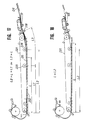
- FIG.16 is a transverse view showing the standby state of the document D6 subsequent to the stoppage and exposure of the preceding document D5.
- L is the length of the document;
- d1 is the interval from the rear end of the preceding document D5 to the front end of the next document D6;
- d2 is the distance (discharge distance) from the document stopper 205 to the discharge roller 235.
- the paper discharge reversal roller 231 continues to turn, and a fixed time after the rear end of the document D has intersected a sensor PS8, a solenoid SD6 is activated.
- a solenoid SD6 is activated.
- FIG.17 is a transverse view showing the conveying of documents of this size.
- the movable pressure roller 226 remains lowered, and the temporary standby position of the front end of the next document D6 is set between the movable pressure roller 226 and the intermediate conveyor roller 218.
- FIG.18 is a transverse view showing the conveying of documents of this size.
- the standby position is located before the glass; or, the next document D6 does not standby and is fed synchronously with the discharge of the previous document D5 from the standby position before the glass; or, the next document D6 is fed out from the nip position of the double-feed prevention roller 217 in the paper feed section 210.
- the previous document D5 is discharged at slow speed.
- the length of the document is determined by the document passage sensor PS7, and the width of the document is determined from the amount of movement of the width regulation plate 214 on the document loading table 211.
- the control of the vertical movement of the movable pressure roller 226 can be set in advance.
- the document size may be also be manually input to memory.
- FIG.19 is a perspective view showing one embodiment of the drive device for the movable pressure roller 226.
- a pair of tension members 223A, 223B are provided, each energized by a spring.
- the tension members 223A, 223B can move parallel to the direction of the document flow, along elongated grooves which are omitted from the drawing.
- the conveyor belt 221 enclosing the drive roller 222 and the follower roller 223 is maintained under tension with no slack by the tension members 223A, 223B.
- the two ends the shaft of the movable pressure roller 226 are supported by a pair of arms 228A, 228B.
- the arm 228A and the arm 228B are integrally formed with a support shaft 229A and a support shaft 229B respectively and supported in a freely swinging manner.
- An arm 229C is integrally mounted on the support shaft 229B.
- a plunger on a latch-type solenoid SD5 is connected to the other end of the arm 229C in a freely rotatable manner.
- the support shafts 229A, 229B are engaged by a bearing 229D and a bearing 229E respectively and are supported in a rotatable manner.
- the arm 229C centered around the support shaft 229B rotates in the counter clockwise direction and the arms 228A, 228B move together and rotate around the support shaft 229B.
- the movable pressure roller 226 swings upward, and separates from the inside surface of the conveyor belt 221 so that the pressure on the conveyor belt 221 is released.
- the slack produced in the conveyor belt at this time is taken up by the energization of the springs on the the tension members 223A, 223B.
- FIG.20 is a perspective view showing another embodiment of the drive device for the movable pressure roller of the present invention.
- a special feature of this embodiment is that the follower roller 223 is supported in a freely rotatable manner in a fixed position, and the slack in the conveyor belt 221 produced in correspondence to the vertical movement of the movable pressure roller 226 is cancelled by means of a tension roller 227A linked to the movable pressure roller 226.
- An arm 228C which supports one end of the movable pressure roller 226, and a corresponding arm 228D which supports the other end are provided in a freely swinging manner on the support shafts 229A, 229B respectively.
- the tension roller 227A is supported in a freely rotatable manner on the other ends of the arms 228C, 228D.
- the support shaft 229B which is integrally formed with the one arm 228D is rotatably driven by the solenoid SD7 in the same manner as in the previous embodiment.
- the solenoid SD7 When the solenoid SD7 is activated the arms 228C, 228D are rotated in the counterclockwise direction, and the movable pressure roller 226 separates from the lower inside surface of the conveyor belt 221, while the tension roller 227A applies pressure to the upper outside surface of the conveyor belt 221.
- FIG.21 is a perspective view showing yet another embodiment of the drive device for the movable pressure roller of the present invention.
- An arm 228E which supports one end of the movable pressure roller 226, and a corresponding arm 228F which supports the other end are provided in a freely swinging manner on the support shafts 229A, 229B respectively.
- a tension roller 227B is supported in a freely rotatable manner at a center position of the arms 228C, 228D.
- the lower end of the arm 229C secured to the other end of the support shaft 229B which is integrally formed with the one arm 228F is connected to the plunger of the solenoid SD7.
- the automatic document conveying device of the present invention not only is it possible to shorten the document conveying time, but by running at slow speed when feeding the document the stability of the separation performance is improved, conveying of documents is smoother, and prevention of damage to the leading edge of the document is even more effective.
- the motor load is reduced and considerable power is saved, making it possible to utilize a small, low torque motor with noise suppression on the device.
- document conveying is based on an ADF start signal from the main copying machine, which starts the motors, clutches, solenoids, and various timers, and control is in response to an optical scan, so that a control program is simple and uncomplicated. There are few factors to cause operational errors, and production losses are greatly reduced.
- the discharge operation is also independent and performed at low speed, so that alignment of the discharged documents is stabilized. Because less than three documents are in motion at any one time, jam control is also simplified.
Landscapes
- Physics & Mathematics (AREA)
- General Physics & Mathematics (AREA)
- Exposure Or Original Feeding In Electrophotography (AREA)
- Delivering By Means Of Belts And Rollers (AREA)
Applications Claiming Priority (4)
| Application Number | Priority Date | Filing Date | Title |
|---|---|---|---|
| JP4161590A JPH03249041A (ja) | 1990-02-22 | 1990-02-22 | 自動原稿搬送装置 |
| JP41615/90 | 1990-02-22 | ||
| JP2054252A JP2849846B2 (ja) | 1990-03-06 | 1990-03-06 | 自動原稿搬送装置 |
| JP54252/90 | 1990-03-06 |
Publications (2)
| Publication Number | Publication Date |
|---|---|
| EP0443619A2 true EP0443619A2 (fr) | 1991-08-28 |
| EP0443619A3 EP0443619A3 (en) | 1992-08-05 |
Family
ID=26381259
Family Applications (1)
| Application Number | Title | Priority Date | Filing Date |
|---|---|---|---|
| EP19910102655 Withdrawn EP0443619A3 (en) | 1990-02-22 | 1991-02-22 | Automatic document conveying device |
Country Status (2)
| Country | Link |
|---|---|
| US (1) | US5223905A (fr) |
| EP (1) | EP0443619A3 (fr) |
Families Citing this family (9)
| Publication number | Priority date | Publication date | Assignee | Title |
|---|---|---|---|---|
| JP3099458B2 (ja) * | 1991-10-18 | 2000-10-16 | ミノルタ株式会社 | 電子写真式複写機 |
| EP0612000A3 (en) * | 1993-02-19 | 1997-07-30 | Canon Kk | Original document feeder. |
| JP3137008B2 (ja) * | 1995-11-10 | 2001-02-19 | 富士ゼロックス株式会社 | 画像形成装置 |
| JP3002860B2 (ja) * | 1995-12-28 | 2000-01-24 | ニスカ株式会社 | 自動原稿送り装置 |
| JP3060361U (ja) * | 1998-10-20 | 1999-08-31 | 船井電機株式会社 | 給紙装置 |
| JP3986884B2 (ja) * | 2002-05-14 | 2007-10-03 | キヤノンファインテック株式会社 | 原稿給送装置及びこれを備えた画像形成装置 |
| TW552233B (en) * | 2002-08-29 | 2003-09-11 | Veutron Corp | A transmission mechanism of auto document feeder |
| TWI320394B (en) * | 2007-02-09 | 2010-02-11 | Primax Electronics Ltd | Automatic document feeder |
| JP2014036425A (ja) * | 2012-08-10 | 2014-02-24 | Canon Inc | 原稿読取装置及び制御方法 |
Family Cites Families (16)
| Publication number | Priority date | Publication date | Assignee | Title |
|---|---|---|---|---|
| JPS5527344B2 (fr) * | 1973-12-26 | 1980-07-19 | ||
| JPS5952812B2 (ja) * | 1977-04-08 | 1984-12-21 | 株式会社リコー | 複写機用原稿自動送り装置に於ける原稿搬送方法 |
| JPS5443035A (en) * | 1977-09-12 | 1979-04-05 | Ricoh Co Ltd | Sheet original conveying device |
| US4470591A (en) * | 1982-08-12 | 1984-09-11 | Xerox Corporation | Variable force document handling system |
| JPS6082550A (ja) * | 1983-10-07 | 1985-05-10 | Toshiba Corp | 紙葉類送り装置 |
| JPH0673034B2 (ja) * | 1984-07-25 | 1994-09-14 | 三田工業株式会社 | 複写機の原稿送り方法 |
| GB2178411B (en) * | 1985-07-02 | 1990-03-14 | Konishiroku Photo Ind | Document feeding apparatus |
| JPH0646320B2 (ja) * | 1986-01-18 | 1994-06-15 | シャープ株式会社 | 自動原稿送り装置 |
| JPH07120093B2 (ja) * | 1987-06-22 | 1995-12-20 | コニカ株式会社 | 原稿搬送装置 |
| JPH01226642A (ja) * | 1988-03-04 | 1989-09-11 | Toshiba Corp | シート給送装置 |
| EP0333107B1 (fr) * | 1988-03-14 | 1993-12-08 | Canon Kabushiki Kaisha | Appareil d'amenée de documents |
| JP2670071B2 (ja) * | 1988-03-14 | 1997-10-29 | キヤノン株式会社 | 原稿搬送装置 |
| JP2608092B2 (ja) * | 1988-03-14 | 1997-05-07 | キヤノン株式会社 | 原稿搬送装置 |
| JP2672579B2 (ja) * | 1988-06-30 | 1997-11-05 | 株式会社東芝 | 自動原稿給送装置 |
| JPH02198947A (ja) * | 1989-01-26 | 1990-08-07 | Toshiba Corp | 画像形成装置 |
| EP0421330B1 (fr) * | 1989-10-02 | 1995-07-05 | Canon Kabushiki Kaisha | Appareil d'alimentation en feuilles |
-
1991
- 1991-02-20 US US07/658,384 patent/US5223905A/en not_active Expired - Fee Related
- 1991-02-22 EP EP19910102655 patent/EP0443619A3/en not_active Withdrawn
Also Published As
| Publication number | Publication date |
|---|---|
| EP0443619A3 (en) | 1992-08-05 |
| US5223905A (en) | 1993-06-29 |
Similar Documents
| Publication | Publication Date | Title |
|---|---|---|
| US5223905A (en) | Automatic document conveying device | |
| US4896876A (en) | Document feeding apparatus | |
| US5328163A (en) | Recording sheet feeding device | |
| EP0411474B1 (fr) | Appareil d'avancement automatique de documents | |
| US4928151A (en) | Apparatus for automatically and circulatively feeding originals | |
| US5118089A (en) | Automatic document feeding apparatus | |
| US5333043A (en) | Image forming apparatus equipped with automatic document feeder | |
| US5502556A (en) | Automatic document feeding apparatus for feeding two-sided documents | |
| JPH03102062A (ja) | 自動原稿搬送装置 | |
| JP3554984B2 (ja) | 自動原稿搬送装置 | |
| US5120039A (en) | Sheet sorter with guide moving device and separate moving device for feeding means mounted on end of guide | |
| JP2709966B2 (ja) | 自動原稿搬送装置 | |
| US5343281A (en) | Automatic document conveyance device | |
| JP2534857B2 (ja) | 原稿搬送装置 | |
| JPH06138734A (ja) | 自動原稿搬送装置 | |
| JPH0663551B2 (ja) | 自動原稿搬送装置の駆動装置 | |
| JP2670629B2 (ja) | 自動原稿搬送装置 | |
| JP2849846B2 (ja) | 自動原稿搬送装置 | |
| JP2686558B2 (ja) | 自動原稿搬送装置 | |
| JP2896685B2 (ja) | 自動原稿搬送装置 | |
| JPH03100563A (ja) | 自動原稿搬送装置 | |
| JP2681698B2 (ja) | 自動原稿搬送装置 | |
| JP2784675B2 (ja) | 原稿自動送り装置 | |
| JPH03102045A (ja) | 自動原稿搬送装置 | |
| JPH06263332A (ja) | 自動原稿送り装置 |
Legal Events
| Date | Code | Title | Description |
|---|---|---|---|
| PUAI | Public reference made under article 153(3) epc to a published international application that has entered the european phase |
Free format text: ORIGINAL CODE: 0009012 |
|
| AK | Designated contracting states |
Kind code of ref document: A2 Designated state(s): DE FR GB |
|
| PUAL | Search report despatched |
Free format text: ORIGINAL CODE: 0009013 |
|
| AK | Designated contracting states |
Kind code of ref document: A3 Designated state(s): DE FR GB |
|
| 17P | Request for examination filed |
Effective date: 19930205 |
|
| STAA | Information on the status of an ep patent application or granted ep patent |
Free format text: STATUS: THE APPLICATION HAS BEEN WITHDRAWN |
|
| 18W | Application withdrawn |
Withdrawal date: 19931215 |