EP0451544A2 - Support pour lame coupante - Google Patents
Support pour lame coupante Download PDFInfo
- Publication number
- EP0451544A2 EP0451544A2 EP91104113A EP91104113A EP0451544A2 EP 0451544 A2 EP0451544 A2 EP 0451544A2 EP 91104113 A EP91104113 A EP 91104113A EP 91104113 A EP91104113 A EP 91104113A EP 0451544 A2 EP0451544 A2 EP 0451544A2
- Authority
- EP
- European Patent Office
- Prior art keywords
- shaft
- blade
- handle
- locking
- approximately
- Prior art date
- Legal status (The legal status is an assumption and is not a legal conclusion. Google has not performed a legal analysis and makes no representation as to the accuracy of the status listed.)
- Granted
Links
- 238000005520 cutting process Methods 0.000 claims description 20
- 238000003780 insertion Methods 0.000 claims description 17
- 230000037431 insertion Effects 0.000 claims description 17
- 238000003825 pressing Methods 0.000 claims description 3
- 238000003892 spreading Methods 0.000 abstract description 4
- 230000002093 peripheral effect Effects 0.000 description 12
- 238000013461 design Methods 0.000 description 6
- 230000002787 reinforcement Effects 0.000 description 4
- 230000000903 blocking effect Effects 0.000 description 3
- 239000000463 material Substances 0.000 description 3
- 238000010079 rubber tapping Methods 0.000 description 3
- 230000007704 transition Effects 0.000 description 3
- XAGFODPZIPBFFR-UHFFFAOYSA-N aluminium Chemical compound [Al] XAGFODPZIPBFFR-UHFFFAOYSA-N 0.000 description 2
- 229910052782 aluminium Inorganic materials 0.000 description 2
- 238000011161 development Methods 0.000 description 2
- 230000018109 developmental process Effects 0.000 description 2
- 238000004519 manufacturing process Methods 0.000 description 2
- 210000002105 tongue Anatomy 0.000 description 2
- 238000012549 training Methods 0.000 description 2
- 238000012546 transfer Methods 0.000 description 2
- 229910000831 Steel Inorganic materials 0.000 description 1
- 230000001154 acute effect Effects 0.000 description 1
- 238000013459 approach Methods 0.000 description 1
- 230000000295 complement effect Effects 0.000 description 1
- 238000009499 grossing Methods 0.000 description 1
- 230000036316 preload Effects 0.000 description 1
- 239000010959 steel Substances 0.000 description 1
Images


Classifications
-
- B—PERFORMING OPERATIONS; TRANSPORTING
- B26—HAND CUTTING TOOLS; CUTTING; SEVERING
- B26B—HAND-HELD CUTTING TOOLS NOT OTHERWISE PROVIDED FOR
- B26B5/00—Hand knives with one or more detachable blades
Definitions
- the invention relates to a holder for knife blades, as e.g. is used for laying or carpet knives.
- the knife expediently has a receptacle for plate-shaped or trapezoidal knife blades which can form straight, sickle-shaped or similar cutting edges.
- a cover of the blade receptacle can advantageously be changed in position after a lock has been released, a parting plane being defined which can lie essentially parallel to the blade plane or in a plate surface of the inserted blade.
- one or more interlocks should also be provided and at least one interlock should be able to be engaged or disengaged essentially only by an approximately linear actuation.
- the invention is further based on the object of creating a knife blade holder of the type mentioned, in which disadvantages of known designs are avoided and which in particular ensures simple and safe handling with simple training.
- one or more interlocks are essentially formed by such connections that at most a rotary movement of less than four to five full rotations, in particular less than 360 °, is required to actuate them between the release of the blade receptacle - and to transfer the locking position.
- the maximum required swivel or rotary movement is suitably less than 180 or 90 ° and can also be less than 30 or 15 °.
- At least one locking device only in a straight line, preferably to provide it with a locking pin which can be used, for example, as a separate component in the assembled shell halves or shaft parts of the handle shaft which limit the blade receptacle.
- the locking bolt can be permanently mounted on one shaft part or can be completely removed from both shaft parts for transfer into the release position.
- a rotary lock can also be formed by pure plug-in members, so that only plug-in locks are provided.
- At least one interlocking acts essentially only parallel to the parting plane, while at least one further interlocking acts at least transversely to the parting plane and possibly also parallel thereto and in a direction transverse to the longitudinal direction of the handle shaft.
- a follow-up lock e.g. it is provided that locking members which are to be rotated or which are to be joined approximately parallel to the parting plane are brought into engagement, after which the opposite release movement is blocked with a further locking member which may be used transversely to the parting plane.
- the shaft parts can be moved relative to one another in and / or transversely to the longitudinal direction of the shaft from the position of use after loosening a corresponding securing device, a latch or the like, approximately parallel to the parting plane or in the area of the blade holder, since they are then particularly safe in the opposite direction and can easily be put together again.
- the two shaft parts can be pivoted relative to one another about an axis of articulation which is approximately parallel or transverse to the longitudinal direction of the shaft and which is preferably approximately at right angles to the parting plane and / or at a distance from the rear shaft end which is greater than the shaft width or shaft thickness.
- This hinge axis in which the shaft parts can be detachably or non-detachably connected to one another, forms a kind of scissor joint at a distance behind the blade receptacle, which does not have to be loosened or loosened for its opening, so that the two shaft parts are always captively connected to one another.
- the hinge axis can form the axis of rotation of one or more rotary locks, which in the longitudinal direction of the shaft on both sides of the hinge axis lie.
- the shaft parts could also be completely separated from one another.
- the two shaft parts are expediently immediately behind and / or in the region of the longitudinal section in which the blade receptacle is located or in front of a connecting bolt, e.g. secured by direct mutual engagement, at least transversely to the blade plane against each other, with securing means or interlocks being able to be provided on both sides of a longitudinal center plane of the handle shaft or approximately in the area of the blade rear edge and / or the cutting edge or in their extensions.
- securing means or interlocks being able to be provided on both sides of a longitudinal center plane of the handle shaft or approximately in the area of the blade rear edge and / or the cutting edge or in their extensions.
- Handle shafts or at least one shell part expediently consist of die-cast aluminum or a material with similar, relatively soft properties, which is why it is advantageous to provide a reinforcement for the most heavily loaded area of the system of the blade back edge, which can be provided by a separate, used or blown component, e.g. made of sheet steel. This component can only be strip-shaped and only rest on part of the length of the back edge.
- the handle shaft also advantageously forms at least one pressing or tapping surface which is suitable for pressing, smoothing or tapping the carpet material to be processed or the like and which can be formed by the rear end face of the handle shaft, which is convexly rounded in side view.
- This surface is expediently completely free of parting lines or similar interruptions essentially over its entire width and / or height, it being possible for all parting lines between the two shaft parts to be offset in relation to this surface. This means that this area can be used with particular care.
- a shaft part can be made shorter, or the tapping surface can be formed by only a single shaft part.
- the associated, recessed end of the one shaft part can be secured with a locking mechanism located on its end face.
- the holder or grip shaft is expediently designed such that it forms two grips lying directly behind one another for almost complete, simultaneous gripping with two hands, without the front hand thereby reaching over the front end of the shaft or into the Range of the blade is sufficient.
- the shaft length is expediently more than 19 or 20 cm, depending on the longitudinal extent of an enlarged handle knob provided at the rear shaft end. Due to a continuously continuous back surface of the handle shaft, which is approximately uniformly convex in a side view, the front hand can also be used advantageously only with the palm of the hand to exert pressure.
- the invention further relates to a blade magazine which is provided with an insertion opening for receiving used blades and / or with a removal opening for removing fresh blades and, for example, has two separate housing spaces for the two types of blades which are parallel to one another.
- the blade magazine is expediently formed by a component that can be completely separated from the holder, in particular a one-piece component, which can be used in the handle shaft, for example, in such a way that it forms a continuous continuation of at least one outside of the handle shaft with at least one outer surface or without relative movement between the shaft parts of their Outside is accessible.
- the receptacle for the magazine can be designed so that it blocks the respective blade against movements from the removal or insertion opening, for example by covering this opening.
- the housing-shaped closed magazine forms a locking bolt, which engages in both shaft parts essentially without play or in the sense of locking them with a low preload, so that the magazine is accessible by itself after unlocking.
- the knife blade holder is used to fasten a blade 2, which forms a cutting edge only on its longest base plate edge and is to be arranged interchangeably between the front ends of two shaft parts 3, 4.
- the blade 2 is placed parallel to and with a plate surface in a parting plane 5 transversely to its plane in a shaft part 3 in a longitudinally secured manner and then positively secured against movement transversely to its plane by covering with the other shaft part 4.
- the shaft parts 3, 4 together form the outer surfaces of a handle shaft, the longitudinal axis 6 of which passes through the center of its end surfaces and with respect to which the blade cutting edge can be offset downwards and at an angle of a few degrees which closes to the rear.
- the two shaft parts 3, 4 are pivotable with a joint 7 located behind the middle of the shaft and in front of the rear third of the shaft length about a joint axis 8 perpendicular to the parting plane 5 over more than 90 and less than 180 ° and beat in the use position in the area of their front Ends together to hold the blades Form 9 for blade 2.
- the shaft parts 3, 4 can only be pivoted relative to one another from the position of use, in which the arm of the shaft part 3, which receives the blade 2 in a recessed manner, is moved like a scissors in the direction away from the other shaft part 4, in which the rear edge of the blade 2 points.
- the shaft part 4 therefore first reaches the blade 2 on the cutting edge delimited by inclined flanks, so that it can run onto the associated side flank of the blade 2 with pretension.
- the two shaft parts 3, 4 are positively secured to one another by at least one locking or securing device 10 to 13.
- a rotary lock 10 extends approximately to the receptacle 9 or to the joint 7 and can also secure the shaft parts against longitudinal movements.
- Two expansion locks 11, 12 are located on both sides in the connection or at a short distance adjacent to the back or cutting side of the blade 2 between the lock 10 and the front end face 15 of the two shaft parts 3, 4 and on both sides of and then to the parting plane 5th These locks 11, 12 also secure in the longitudinal direction like the further lock 13. This is provided behind the joint 7 and in front of the rear end face of the shaft part 3. Although it can be completely disengaged, it comes into engagement before the approximately simultaneous engagement of the fuses 11, 12.
- a adapted to the blade 2 shallow recess 14 is provided, on the flat bottom adjacent to the end surface 15, a single cam 16 for the optional engagement in several consecutive cutouts on the Back edge of the blade 2 protrudes.
- the blade 2 can optionally be used so that its back edge is completely within the handle shaft lies or protrudes beyond the end face 15.
- a longitudinal boundary of the recess 14 forms a back rest 17 for the back edge of the blade 2 and the opposite longitudinal boundary a cutting edge rest 19.
- the back rest 17 is formed by an inserted, web-shaped reinforcement 18 which can extend to the front end face 15 or can be set back slightly .
- the reinforcement 18 is formed by an angular profile
- the inner surface of its one leg lying in the plane of the bottom of the recess 14 is expediently recessed in the corner area in the manner of a groove in order to ensure that the blade 2 lies securely on the side.
- the system 19 essentially connects to the end face 15 penetrated by the recess 14 in the form of a slot and extends only over a small part of the length of the recess 14 or the blade cutting edge, which is gently received behind it.
- the joint 7 is essentially formed by a joint pin 20 passing through one or both shaft parts, the joint axis 8 of which can lie above the longitudinal axis 6 approximately in the middle of the associated shaft height or also slightly off-center or below or in the longitudinal axis.
- the hinge pin 20 can be formed in one piece with a shaft part, as a separate plug pin and / or as a tensioning or rivet pin, the respective end of which, e.g. is secured by riveting, screwing or the like relative to the associated shaft part 3 or 4.
- each shaft part 3 or 4 has a projection 25 or 27 which is adjacent to or adjoins the associated longitudinal edge and which projects transversely over the associated inner surface, up to the front end surface 15 and / or approximately to the locking device 10 extends at least over the entire length of the receptacle 9 and itself extends continuously from the associated longitudinal edge at most to the adjacent longitudinal limit of the receptacle 9.
- Each projection 25 and 27 on the other shaft part 4 and 3 is assigned a recessed, closely adapted shoulder 26 and 28 in the form of an angular recess in the side view of the associated longitudinal edge.
- the respective projection fills the associated shoulder so that the projection not only forms a continuation of the associated longitudinal edge of the handle shaft, but also the part of the side surface of the other shaft part 4 or 3 interrupted by the shoulder or only the transition to this side surface .
- the protrusions protruding in opposite directions can be narrow in the manner of webs.
- the projection 25 of the shaft part 3 adjoins the back surface 29 thereof; the projection 27 of the shaft part 4 connects to the opposite longitudinal edge thereof, which forms a part of the underside 30 of the handle shaft in the use position.
- One side flank of the elongated plug opening 22 or the plug member 21 lies in the parting plane or the associated inner surface of the shaft part 4 or 3, while the other side flank can be slightly inclined so that the shaft parts transversely to the parting plane when the plug members are inserted into one another against each other are subjected to a clamping torque.
- the end flanks of the connectors are also complementary inclined, so that they can align each other well in the event of any joint play.
- the bottom surface of the plug-in opening 22 lies at a short distance approximately parallel to the associated section of the back of the shaft 29.
- the shoulder 28 and the projection 27 adjoining the underside 30 are also provided with a single plug-in member 23 and a plug-in opening 24, which, however, on the other side of the parting plane 5.
- the shoulder 28 lies at a smaller distance from the system 19.
- Both projections 25, 27 and / or both plug openings 22, 24 are approximately of the same length and / or extend approximately over the same longitudinal section of the shaft.
- the plug-in members 21, 23 are provided completely sunk between the upper and lower longitudinal edges and between the side surfaces of the shaft. They expediently extend approximately to the rear end of the respective projection and have a longitudinal distance from the lock 10 which is smaller than their length.
- the interlocking parts of the locks or safeguards 11, 12 can also extend over part of the longitudinal region of the handle shaft in which the blade 2 lies.
- the lock 10 has a plug-in latch 31 which is to be inserted from a side surface of the handle shaft, is elongated in the longitudinal direction of the handle shaft or is rectangular in view of one or more sides, which extends approximately over the entire height or width of the handle shaft and / or which extends approximately to the projections 25, 27 or the hinge pin 20.
- the plug-in bolt 31 shown only in FIG. 4 can be inserted into a receptacle opening 32 which is delimited by the two shaft parts 3, 4 and which corresponds exactly to its associated outer contour.
- a cup-shaped receiving pocket 33 is provided in the inner surface of the shaft part 3, the wall-like thin bottom of which forms the associated side surface 39 of the handle shaft with its outside.
- a window-like opening 34 which is congruent with the receiving pocket 33 is provided.
- the inserted locking bolt 31 forms a shear lock against opening the handle shaft.
- a bolt lock 35 e.g. a resilient locking or snap lock in the form of locking openings 36 in the shaft part 3 and engaging locking pin 37 on the locking bolt 31 is provided.
- Two locking openings 36 lying one behind the other in the longitudinal direction of the shaft are provided as openings in the bottom wall of the receiving pocket 33, and the locking bolt 31 has on its associated, flat outside the corresponding, projecting locking pins 37, which can have slightly enlarged end collars as snap links.
- the end surfaces of the locking pin 37 form continuously flush continuations of the bulbous side surface 39 and push buttons which are exposed adjacent to both ends of the locking bolt 31 as handles for unlocking and pushing the locking bolt 31 out of the receiving opening 32.
- the curved outer surface of the locking bolt 31 facing away therefrom forms a continuous one and continuation of the associated, also bulbous grip or side surface 38, which is flush on all sides.
- the locking bolt 31 is designed as a housing-shaped magazine 40 in which the blades 2 can be accommodated parallel to the parting plane 5, so that the blades are accessible even when the receptacle 9 is not opened or the shaft parts 3, 4 do not move out of the position of use will.
- At least one locking cam engaging in an opening or a non-symmetrical shape of the outer edges of the locking bolt can be provided so that the locking bolt can only be used in a single longitudinal orientation.
- the locking or securing 13 extends over the entire associated shaft height and, as a plug-in member 41, has an arch bridge which projects at the rear end of the shaft part 3, lies with a flank in the parting plane 5, is curved around the joint axis 8 and / or up to both longitudinal edges of the shaft part 4 are sufficient.
- This plug-in member 41 is assigned a correspondingly curved plug-in groove 42 as a plug-in opening, which can be open at both ends, is provided in an arch shoulder of the shaft part 3 projecting above the parting plane, in front of the furthest region of a rear handle knob 43 or behind one of the most tapered handle waist 44 of the handle shaft and / or in the transition region between the knob 43 and this handle waist.
- the arch web 41 can be moved out of at least one end of the plug-in groove 42.
- the shaft parts form a parting line lying transversely to the blade plane, which can extend from the two ends in each case to the associated outer boundary of the handle shaft, that is to say, for example, it extends over the entire associated extension of the handle shaft.
- this parting line lies instead of lengthways transversely or approximately at right angles to the longitudinal direction of the shaft and only extends over part of the shaft width.
- the rear end of the shaft part 4 thus protrudes less far than the shaft part 3 via the articulation axis 8. With its protruding end or the knob 43, this forms a knocking surface 45 which is slightly curved in side view and more curved into the knob horns in the manner of a rounded hammer surface .
- the one-piece knob 43 forms the highest region of the handle shaft in side view and the widest region in plan view according to FIG. 5.
- the handle shaft is tapered towards the front both in side view and in plan view through concave outer boundaries, whereby it has its slimmest area between the rear two quarters of its shaft length and then increases again in both views to the front, so that it is approximately from the Joint axis 8 or over the front two thirds of its length continuously convex or bulbous side surfaces and long sides.
- the side surfaces 38, 39 run towards the front end surface 15 approximately at an acute angle at an average angle of substantially less than 30 or 20 ° to one another, so that the holder can be made very narrow in the front region.
- the specified arrangements, positions, dimensions and the like Apart from exactly as described, they can also be provided only approximately, essentially or differently; Furthermore, the associated training courses can be provided only one or more times.
- the rear, continuously concave area of the underside of the handle shaft extends forward further than the upper, continuously concave area, namely approximately up to half the shaft length, in such a way that the shaft is approximately constant at right angles over its entire longitudinal section that adjoins the front Center shaft height to be measured.
- the grip shaft thereby forms a rear, slimmer and slightly extended grip part 46 which continuously increases in height at the shaft extended and continuous in the same direction curved longitudinal edges front handle portion 47 passes.
- the rear grip part 46 is used for complete gripping with one hand, to which another hand, which also completely surrounds the front grip part 47, can directly connect.
- the magazine 40 has a magazine chamber which is separated by an intermediate spreading leaf spring 50 into two adjacent chambers 48, 49, one of which e.g. is intended for stacked fresh knife blades.
- the chamber 48 for new blades has a slot-shaped removal opening 51 on a longitudinal side of the magazine housing, while the chamber 49 has a corresponding slot-shaped insertion opening 52 for inserting used blades into the chamber 49.
- the removal or insertion openings can be provided on the same side of the housing or on opposite sides.
- the top or bottom wall of the magazine housing is expediently provided with a finger cutout in the region of the removal opening, through which new blades can be gripped more easily.
- the chambers 48, 49 change their size due to the movable spring 50, which forms a subdivision and resilient fixing, in accordance with the removal of new blades and the input of used blades.
- the spring presses the blades against the outer walls and prevents them from falling out.
- protruding, differently wide securing cams 53, 54 can be provided on the longitudinal and / or narrow sides, to which closely matched recesses are assigned in the associated walls of the opening 34 and the receiving pocket 33.
- the cam 54 located at the joint 7 is wider than the opposite cam 53, so that the magazine 40 can only be used in a predetermined longitudinal orientation. Its longitudinal outer sides then form blocking surfaces 55, 56 which are approximately parallel to the plane mutual locking of the shaft parts 3, 4. Except for the outer side associated with the side surface 38, all the other outer surfaces of the magazine 40 are expediently essentially flat.
- the outside facing away from the locking pin 37 is convexly curved corresponding to the opposite side surface 39 and is located as part-grip surface 38a on the right-hand side of the grip, so that it lies on the palm of the hand when the holder is used with right-handed use.
- the magazine 40 can be produced as a molded part made of plastic, the bottom and / or top wall of which are fastened to a base body forming the magazine chambers by snap connections.
- the base body expediently has the cams, while the base wall is formed in one piece with the locking pins 37.
- the cover wall forms part of the associated lateral handle surface in the manner of an inserted handle shell.
- the shaft parts 3, 4 can delimit at least one further chamber, which is expediently located behind the hinge axis 8 and is only accessible when the handle shaft is open.
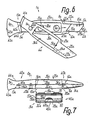
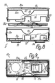
- FIGS. 6 to 9 the same reference numerals are used for corresponding arrangements as in FIGS. 1 to 5, but with the index "a”, which is why all parts of the description apply analogously to all embodiments and any arrangements or features of all embodiments in any combination or Addition can be provided in further embodiments.
- the blade receptacle 9a has no separate reinforcement, but the support surfaces for the back and the cutting edge of the blade 2a are in one piece formed with the shaft part 3a or the projection 25a and the plug member 23a, so that the back of the blade 2a directly on the back rest 17a formed by the projection 25a made of aluminum, plastic or the like.
- the cutting edge only with a rear part of its longitudinal extent can directly support the cutting system 19a, which is formed by a front end section of the plug-in member 23a and also consists of at least one of the materials mentioned.
- the shoulder 28a connected to the front of the plug-in member 23a lies here in the area of the blade cutting edge, so that in the side view according to FIG.
- the shoulder 28a forms an oppositely pointing, approximately continuous continuation of the system 19a.
- the cutting system is also formed by the inner shoulder of the projection 27a, which then lies essentially against the shoulder 28a or the blade cutting edge.
- the recess 14 could also be dispensed with entirely, because the cutting attachment 19a can be formed entirely by the other shaft part 4a or its projection 27a.
- each cam 16a lying one behind the other is provided on the back support 17a on the inner surface of the shaft part 3a and each cam 16a is assigned a corresponding pocket-shaped receiving recess on the inner surface of the other shaft part 4a, which does not extend to the outer or side surface thereof and into which the cam 16a enters when the shaft parts 3a, 4a are closed, so that in this way a further protection against longitudinal movements of the two shaft parts 3a, 4a is formed in their foremost region in front of the safety devices 11a, 12a and immediately behind the end face 15a. Even in the event of a possible spreading of the two shaft parts 3a, 4a in the foremost region, the blade 2a cannot move out release their positive locking against the holder 1a.
- the receiving recesses directly adjoin the shoulder 26a in a groove-like manner.
- the plug opening 22a of the fuse 11a is formed by a groove which runs continuously between the rear extension of the back rest 17a and the shaft back 29a and which is inclined slightly obliquely towards the shaft back 29a and into which the plug member 21a at least in the region when the holder 1a is closed of the shaft back 29a fully engages.
- the plug-in member 21a connects to the rearmost end of the shoulder 26a, namely to a transverse shoulder extending from the shoulder 26a to the back of the shaft 29a, up to which the plug-in member 21a also extends so that it forms part of the back of the shaft when the holder 1a is closed.
- the plug-in member 23a also connects to a rear transverse shoulder of the shoulder 28a, this cross-shoulder passing through to the underside 30a of the holder 1a, but the plug-in member 23a is set back in relation thereto, so that the pocket-shaped plug-in opening 24a passes through to the rear end of the projection 27a can, but its bottom surface is set back from the bottom 30a.
- the back support 17a and the shoulder 26a can pass approximately in a straight line or plane from the rear end to the front end in a side view.
- the back of the shaft 29a formed here solely by the shaft part 3a is expediently arranged approximately parallel to the back rest 17a in a side view and rounded only in the foremost region for the transition into the end face 15a, so that there is a high level of support stability against the cutting forces that occur.
- the plug-in member 41a and the plug-in opening 42a of the fuse 13a expediently do not extend all the way to the underside 30a, but stand back from them by a few millimeters, so that behind the rear end of the shank part 4a, which has the projecting plug-in member 41a, the underside 30a solely through the shank part 3a is formed.
- the entire end of the rear end of the shaft part 4a lies against a transverse shoulder of the shaft part 3a through which the plug opening 42a passes, adjacent to the outer side flank of the plug element 41a.
- the joint 7a expediently has a screw bolt 20a which lies in the joint axis 8a and is inserted from the side surface of the shorter shaft part 4a and which engages with a threaded section in a projection projecting beyond the inner surface of the shaft part 3a, which in the manner of a pivot pin engages in a recess engages the inner surface of the shaft part 4a.
- the hinge pin 20a expediently bears with an annular shoulder, for example formed by a thread-free bolt section, on the end face of the attachment and slides with a further annular shoulder, for example formed by a bolt head, on a corresponding counter shoulder of the shaft part 4a, so that thereby the axial play between the two shaft parts 3a, 4a is precisely predetermined, while the shoulder engaging in the recess can also absorb high radial forces, in particular directed transversely to the longitudinal direction of the holder 1a.
- the head of the hinge pin 20a is completely sunk in the side surface of the shaft part 4a and Threaded portion engages in a blind hole of the shaft part 3a, so that it does not extend to the opposite side surface 39a.
- the magazine 40a provided as a locking bolt 31a has a housing which is adapted to the shape of the blade in its rectangular inner cross section in that the length of this cross section corresponds to the length of the blade cutting edge and the width of this inner cross section corresponds to the distance between the blade cutting edge and the back of the blade.
- the housing is composed of two essentially rectangularly limited, cup-shaped housing parts 57, 58, both of which each have four circumferential walls that extend approximately at an angle to one another over the entire height of the housing, so that the housing in the assembled state except on the floor and on the top wall in Area of one to all peripheral walls is essentially double-walled.
- the housing part 57 essentially forms all of the outer surfaces of the housing except in the region of the top wall 60.
- the two housing parts 57, 58 are secured to one another by means of at least one snap connection which snaps in during assembly.
- a barb-like protruding snap cam 63 with a locking surface facing the shoulder of the cover wall 60 is provided on the outer sides of each associated peripheral wall of the housing part 58, to which a snap opening 64 is assigned in the associated peripheral wall of the housing part 57, which is angular to extends into the bottom 59.
- the snap cam 63 is resiliently movable due to the resilient properties of the associated peripheral wall and is easily accessible from the outside for unlocking or opening the housing.
- the longitudinal edge of the associated cup opening of the front wall 62 of the housing part 58 lying on one longitudinal side of the housing is set back by approximately the same amount as the associated longitudinal edges of all the other three peripheral walls by which the longitudinal edge of the corresponding front wall 61 of the housing part 57 closer to the floor 59 is set back relative to the inside of the bottom wall 59.
- these two longitudinal edges of the front walls 61, 62 form a linear longitudinal boundary of the slot-shaped removal opening 51a, which extends essentially over the entire length of the housing, the opposite boundary of which is formed by the inside of the base 59.
- the two other longitudinal boundaries of the front walls 61, 62 namely the longitudinal boundary of the front wall 61 located at the associated cup opening, as set back, as explained, and the longitudinal boundary of the front wall 62, which is spaced apart from the inside of the top wall 60, together form a longitudinal boundary of the insertion opening 52a, the other longitudinal boundary of which is formed by the inside of the top wall 60.
- Provided in the bottom wall 59 is at least one opening or cutout 67 which extends over the largest part of the housing depth and which adjoins the front edge of the bottom wall 59 located at the removal opening 51a and expediently lies approximately in the middle thereof or between the pins 37a.
- cams protruding into the housing are expediently provided, which form guide bevels 65, which approach the removal opening 51a from the inside of the housing rear wall to the housing base 59 at a few angular degrees.
- guide bevels 65 which approach the removal opening 51a from the inside of the housing rear wall to the housing base 59 at a few angular degrees.
- the bottom blade in each case is inevitably displaced slightly in the direction of the removal opening 51a or so that it already engages between the longitudinal boundaries of the removal opening.
- These cams are expediently provided on the inside of the rear wall of the outer housing part 57 and engage through cutouts 66 in the rear wall of the inner housing part 58.
- At least one part-circular concave cutout 68, 69 extending to the associated boundary edge lying at the insertion opening 52a is provided in the manner of a breakthrough, the two cutouts 68, 69 lying approximately in the middle of the housing length expediently together forming a finger opening which extends in cross section through the housing into the front wall and the top wall.
- the front wall 61 of the outer housing part 57 has a cutout 70 which is approximately congruent with the cutout 69.
- the two pins 37a are provided on the outer housing part 57 and protrude in a cup shape approximately by the wall thickness of the base 59 beyond the outside thereof. They are slightly offset with respect to the longitudinal center plane of the magazine 40a, as a result of which incorrect insertion of the magazine 40a in its two positions rotated about a transverse axis is excluded.
- the outer narrow sides of the housing merge sharply into the outside of the rear wall of the housing or the blocking surface 56a, while they merge into the front wall of the housing or the blocking surface 55a, so that the magazine 40a is inserted incorrectly the receiving opening 32a is not possible.
- the bottom of the receiving opening 32a is essentially flat, corresponding to the outside of the bottom 59 of the magazine 40a, the side surface 39a of the shaft part 3a being substantially flat in this area, so that a bottom wall with an approximately constant wall thickness results for the receiving opening 32a.
- the end surfaces of the pins 37a can also be flat and lie in the plane of the side surface 39a.
- a locking cam 53a in the form of a spherical cap-shaped projection on the outside of the housing part 57 is provided approximately in the middle of the housing height, which has a locking opening in the associated side surface of the receiving opening 32a 54a is assigned.
- This locking opening 54a is advantageously approximately symmetrical to the parting plane 5a, so that it is formed by both shaft parts 3a, 4a when the holder 1a is closed.
- sliding grooves extending to the insertion opening can be provided for the locking cam 53a, each connecting to one of the locking openings 54a and having a smaller depth than this, so that the locking cam 53a only with increased friction in can slide them until he is in the latching opening 54a springs in or is released on the outside of the side surface 38a.
- the pins 37a Due to the locking cams 53a, the pins 37a can have constant circumferential surfaces over their height, since they themselves no longer need to have a locking function.
- the bolt is loaded by the shaft parts on the locking surfaces due to shear.
- a one-piece intermediate floor 50a is provided, which is guided only by sliding its outer edges on the inner surfaces of the peripheral walls of the housing part 58.
- This intermediate floor has, on its side facing the top wall 60, two longitudinal webs projecting along its longitudinal edges, over which two springs 71 projecting freely in the longitudinal direction toward one another and protruding in the manner of tongues and having cam-shaped curved end sections. These springs 71 lie between the longitudinal webs and are formed in one piece from the base plate.
- the springs 71 can thereby be pressed resiliently into cutouts in the base plate and can be supported with their cam-like protrusions either on the inside of the top wall 60 or on the flat sides of used blades which have been inserted via the insertion opening 52a.
- the base plate On the outside facing away from these cusps, the base plate has at least two or three cams 72 which are spaced one behind the other in the longitudinal direction and are curved in cross section, which are web-like and transverse to the longitudinal direction of the intermediate base 50a and adhere to the blades to be pulled out through the removal opening 51a can support the inside of the bottom 59.
- Two cams 72 lie at a short distance adjacent to the ends of the intermediate floor 50a or in the region of the roots of the springs 71, while a further cam 72 lies approximately in the middle between them.
- the substantially flat base plate of the intermediate base 50a expediently has cutouts so that it does not hinder a possible unlocking of the snap connections.
- the magazine 40a can thus be opened at any time to replace the blades, ie can be reused.
Landscapes
- Life Sciences & Earth Sciences (AREA)
- Forests & Forestry (AREA)
- Engineering & Computer Science (AREA)
- Mechanical Engineering (AREA)
- Knives (AREA)
- Treatment Of Fiber Materials (AREA)
- Scissors And Nippers (AREA)
- Sampling And Sample Adjustment (AREA)
Applications Claiming Priority (2)
| Application Number | Priority Date | Filing Date | Title |
|---|---|---|---|
| DE4009905 | 1990-03-28 | ||
| DE4009905A DE4009905A1 (de) | 1990-03-28 | 1990-03-28 | Messerklingen-halter |
Publications (3)
| Publication Number | Publication Date |
|---|---|
| EP0451544A2 true EP0451544A2 (fr) | 1991-10-16 |
| EP0451544A3 EP0451544A3 (en) | 1992-01-22 |
| EP0451544B1 EP0451544B1 (fr) | 1994-06-22 |
Family
ID=6403213
Family Applications (1)
| Application Number | Title | Priority Date | Filing Date |
|---|---|---|---|
| EP91104113A Expired - Lifetime EP0451544B1 (fr) | 1990-03-28 | 1991-03-16 | Support pour lame coupante |
Country Status (5)
| Country | Link |
|---|---|
| US (1) | US5404645A (fr) |
| EP (1) | EP0451544B1 (fr) |
| JP (1) | JPH0738901B2 (fr) |
| AT (1) | ATE107561T1 (fr) |
| DE (2) | DE4009905A1 (fr) |
Cited By (7)
| Publication number | Priority date | Publication date | Assignee | Title |
|---|---|---|---|---|
| FR2688438A1 (fr) * | 1992-03-10 | 1993-09-17 | Stanley Works | Manche de cutter a lame retractable. |
| WO1994004324A1 (fr) * | 1992-08-12 | 1994-03-03 | Turner Intellectual Property Limited | Outil a main possedant une lame retractible |
| EP0485764B1 (fr) * | 1990-11-13 | 1997-03-19 | Becton, Dickinson and Company | Poignée de couteau |
| EP0726124A3 (fr) * | 1995-02-08 | 1998-03-11 | MARTOR-ARGENTAX E.H. Beermann KG | Couteau, notamment couteau tapis, à lame échangéable |
| FR2859938A1 (fr) * | 2003-09-23 | 2005-03-25 | Inrs Inst Nat De Rech Et De Se | Outil tranchant perfectionne a lame amovible et lame pour un tel outil |
| EP2752276A1 (fr) * | 2013-01-04 | 2014-07-09 | Martor Kg | Outil de coupe avec lame interchangeable et procédé d'échange d'une lame interchangeable |
| DE202018106114U1 (de) | 2018-10-25 | 2018-11-07 | Jürgen Hoffmann | Schneidhobel-Handwerkzeug |
Families Citing this family (41)
| Publication number | Priority date | Publication date | Assignee | Title |
|---|---|---|---|---|
| US5644843A (en) * | 1995-10-30 | 1997-07-08 | Young; Monte | Easily loaded utility knife |
| GB2310818A (en) * | 1996-03-06 | 1997-09-10 | Stanley Works Ltd | Hand-held utility knife |
| DE19621367A1 (de) * | 1996-05-29 | 1997-12-04 | Reddig Gmbh | Verlegemesser |
| US5862596A (en) * | 1997-06-09 | 1999-01-26 | Chung; Yen-Chao | Hand held cutter |
| US6026575A (en) * | 1997-11-14 | 2000-02-22 | American Safety Razor Company | Utility knife handle |
| USD406220S (en) * | 1998-04-29 | 1999-03-02 | Pacific Handy Cutter, Inc. | Utility knife blade |
| USD406221S (en) * | 1998-04-29 | 1999-03-02 | Pacific Handy Cutter, Inc. | Utility knife blade |
| US6101721A (en) * | 1999-05-20 | 2000-08-15 | 1360314 Ontario Limited | Cutting/scraping tool |
| USD437764S1 (en) | 1999-11-10 | 2001-02-20 | Roberts Consolidated Industries, Inc. | Carpet knife |
| US6560873B1 (en) | 1999-11-12 | 2003-05-13 | Mel Wayne Ortner | Automatic safety knife |
| US6415514B1 (en) * | 2000-08-03 | 2002-07-09 | Tseng Min Chun | Artistic knife with replaceable blade magazine |
| USD455061S1 (en) | 2001-04-17 | 2002-04-02 | Yin Han Huang | Utility knife |
| US6574872B2 (en) | 2001-05-04 | 2003-06-10 | The Stanley Works | Utility knife |
| US6966113B2 (en) | 2001-07-23 | 2005-11-22 | Repetto Llc | Utility knife |
| US6971178B2 (en) * | 2002-09-05 | 2005-12-06 | The Stanley Works | Replaceable blade knife |
| US7509742B2 (en) * | 2002-11-19 | 2009-03-31 | Earl & Kimberly Votolato, Trustees Of The Votolato Living Trust | Safety cutting apparatus |
| GB2398754B (en) * | 2003-02-26 | 2005-02-16 | Yin-Hae Huang | A knife |
| US7051443B2 (en) * | 2003-04-29 | 2006-05-30 | Kristopher Joseph Mueller | Multi-function heavy duty utility knife with stabilizer pivot structure |
| USD576858S1 (en) * | 2004-07-15 | 2008-09-16 | Tjm Design Corporation | Grip for hand-held saw |
| US7434317B2 (en) * | 2004-09-23 | 2008-10-14 | Irwin Industrial Tool Company | Slide assembly device for a snap-off blade utility knife |
| US20060137191A1 (en) * | 2004-12-27 | 2006-06-29 | Ray Hightower | Hot knife roof cutting tool |
| US7107688B1 (en) * | 2005-04-18 | 2006-09-19 | Cooper Brands, Inc. | Releasable blade locking mechanism for utility knife |
| US7279210B2 (en) * | 2005-09-07 | 2007-10-09 | 3M Innovative Properties Company | Curable compositions, methods of making and using the same, and articles therefrom |
| US7389587B2 (en) * | 2005-09-08 | 2008-06-24 | Helen Of Troy Limited | Utility knife |
| WO2007126776A2 (fr) * | 2006-04-04 | 2007-11-08 | Acme United Corporation | Outil de coupe à cartouche |
| US20070256310A1 (en) * | 2006-05-02 | 2007-11-08 | Pool Dan B | Utility Knife With Cam Clamping Means |
| US7774942B2 (en) * | 2006-10-09 | 2010-08-17 | Pacific Handy Cutter, Inc. | Utility knife |
| WO2008103821A2 (fr) | 2007-02-23 | 2008-08-28 | Donaldson Company, Inc. | Élément de filtre formé |
| US9840013B2 (en) * | 2008-04-29 | 2017-12-12 | Pacific Handy Cutter, Inc. | Safety cutter with blade change/storage mechanism |
| JP5309360B2 (ja) * | 2008-07-31 | 2013-10-09 | 三菱電機株式会社 | 半導体装置およびその製造方法 |
| WO2010083426A1 (fr) * | 2009-01-16 | 2010-07-22 | American Safety Razor Company | Couteau à moquette à lame rétractable |
| US20110271531A1 (en) * | 2010-05-04 | 2011-11-10 | Chin-Chen Huang | Opening and closing mechanism for utility knife |
| US8572850B2 (en) * | 2010-06-19 | 2013-11-05 | Yuewei Wu | Carpet knife |
| US8689450B2 (en) * | 2011-04-29 | 2014-04-08 | Acme United Corporation | Knife having a reversible carriage |
| JP6376586B2 (ja) * | 2013-10-18 | 2018-08-22 | 株式会社貝印刃物開発センター | 医療用ナイフ |
| US9808942B2 (en) * | 2014-03-12 | 2017-11-07 | Hangzhou Great Star Tools Co., Ltd. | Knife with replaceable blade |
| CN106737880B (zh) * | 2016-11-23 | 2018-08-14 | 四川城市职业学院 | 一种双面出鞘研磨美工刀 |
| US20180333870A1 (en) | 2017-05-16 | 2018-11-22 | Garland Industries, Inc. | Utility Knife |
| GB2575073B (en) * | 2018-06-27 | 2021-01-13 | The Safety Knife Co Ltd | Knife |
| US10800052B1 (en) | 2019-06-13 | 2020-10-13 | Repetto Llc | Utility knife, blade, and cartridge |
| FI4237347T3 (fi) * | 2020-10-27 | 2025-02-12 | Fiskars Finland Oy Ab | Teräannostelija |
Family Cites Families (20)
| Publication number | Priority date | Publication date | Assignee | Title |
|---|---|---|---|---|
| US2131358A (en) * | 1936-02-11 | 1938-09-27 | Rothschild Sol | Scalpel |
| US2187590A (en) * | 1938-08-16 | 1940-01-16 | August J Lurie | Utility knife |
| US3509627A (en) * | 1967-12-06 | 1970-05-05 | Stanley Works | Utility knife |
| DE1932139A1 (de) * | 1969-06-25 | 1971-01-21 | Dynamit Nobel Ag | Verfahren zur Herstellung tiefgezogener Hohlkoerper |
| US3593417A (en) * | 1969-08-13 | 1971-07-20 | Stanley Works | Hand tool having a holder for spare blades and the like |
| US3660896A (en) * | 1970-04-10 | 1972-05-09 | Russell Harrington Cutlery Inc | Utility knife |
| FR2105412A5 (fr) * | 1970-08-13 | 1972-04-28 | Stanley Works | |
| GB1413679A (en) * | 1972-10-17 | 1975-11-12 | Jra Steel Processing Ltd | Cutting blade holders |
| US3927473A (en) * | 1974-04-18 | 1975-12-23 | Philip Morris Inc | Replaceable blade knife |
| US4005525A (en) * | 1975-08-29 | 1977-02-01 | Allway Tools Inc. | Retractable cutting implement |
| JPS5751010Y2 (fr) * | 1978-02-13 | 1982-11-08 | ||
| US4524518A (en) * | 1983-06-13 | 1985-06-25 | The Stanley Works | Utility knife |
| US4604805A (en) * | 1983-12-14 | 1986-08-12 | John F. Cuscovitch | Holder for detachable blades |
| EP0148546A1 (fr) * | 1984-01-11 | 1985-07-17 | The Stanley Works Limited | Ciseau à main |
| JPS6123973U (ja) * | 1984-07-16 | 1986-02-13 | エヌティー株式会社 | マガジン式カツタナイフ |
| DE3511091A1 (de) * | 1985-03-27 | 1986-10-09 | Bernd 2841 Drebber Reddig | Verlegemesser, insbesondere teppichmesser |
| DE3600318A1 (de) * | 1985-03-27 | 1987-07-09 | Bernd Reddig | Verlegemesser, insbesondere teppichmesser |
| CH671917A5 (fr) * | 1987-03-10 | 1989-10-13 | Szabo S Ag | |
| GB8708112D0 (en) * | 1987-04-04 | 1987-05-13 | Paramo Tools Group Ltd | Knife |
| GB2206517A (en) * | 1987-05-08 | 1989-01-11 | Stanley Works Ltd | Improvements in utility knives |
-
1990
- 1990-03-28 DE DE4009905A patent/DE4009905A1/de not_active Withdrawn
-
1991
- 1991-03-16 AT AT91104113T patent/ATE107561T1/de not_active IP Right Cessation
- 1991-03-16 EP EP91104113A patent/EP0451544B1/fr not_active Expired - Lifetime
- 1991-03-16 DE DE59101967T patent/DE59101967D1/de not_active Expired - Fee Related
- 1991-03-28 JP JP3064876A patent/JPH0738901B2/ja not_active Expired - Fee Related
-
1993
- 1993-04-29 US US08/054,942 patent/US5404645A/en not_active Expired - Lifetime
Cited By (9)
| Publication number | Priority date | Publication date | Assignee | Title |
|---|---|---|---|---|
| EP0485764B1 (fr) * | 1990-11-13 | 1997-03-19 | Becton, Dickinson and Company | Poignée de couteau |
| FR2688438A1 (fr) * | 1992-03-10 | 1993-09-17 | Stanley Works | Manche de cutter a lame retractable. |
| WO1994004324A1 (fr) * | 1992-08-12 | 1994-03-03 | Turner Intellectual Property Limited | Outil a main possedant une lame retractible |
| EP0726124A3 (fr) * | 1995-02-08 | 1998-03-11 | MARTOR-ARGENTAX E.H. Beermann KG | Couteau, notamment couteau tapis, à lame échangéable |
| FR2859938A1 (fr) * | 2003-09-23 | 2005-03-25 | Inrs Inst Nat De Rech Et De Se | Outil tranchant perfectionne a lame amovible et lame pour un tel outil |
| EP2752276A1 (fr) * | 2013-01-04 | 2014-07-09 | Martor Kg | Outil de coupe avec lame interchangeable et procédé d'échange d'une lame interchangeable |
| US9539732B2 (en) | 2013-01-04 | 2017-01-10 | Martor Kg | Cutting tool with interchangeable blade and method for replacing an AC-blade |
| DE202018106114U1 (de) | 2018-10-25 | 2018-11-07 | Jürgen Hoffmann | Schneidhobel-Handwerkzeug |
| EP3643465A1 (fr) | 2018-10-25 | 2020-04-29 | Jürgen Hoffmann | Outil manuel de type rabot de coupe |
Also Published As
| Publication number | Publication date |
|---|---|
| EP0451544B1 (fr) | 1994-06-22 |
| DE59101967D1 (de) | 1994-07-28 |
| JPH04214464A (ja) | 1992-08-05 |
| US5404645A (en) | 1995-04-11 |
| JPH0738901B2 (ja) | 1995-05-01 |
| EP0451544A3 (en) | 1992-01-22 |
| DE4009905A1 (de) | 1991-10-02 |
| ATE107561T1 (de) | 1994-07-15 |
Similar Documents
| Publication | Publication Date | Title |
|---|---|---|
| EP0451544B1 (fr) | Support pour lame coupante | |
| EP1479487B1 (fr) | Couteau | |
| DE69202384T2 (de) | Ratschenschlüssel. | |
| DE69809648T2 (de) | Aufklappbares Werkzeug wie aufklappbares Messer | |
| DE68906356T2 (de) | Verriegelbares Schieberpaar. | |
| EP3214965B1 (fr) | Poignée de bâton de randonnée | |
| DE3007690A1 (de) | Einstellbare halterung, insbesondere tuergriffanordnung fuer motorfahrzeuge | |
| DE2618674B2 (de) | Steckschlüsselbetätigter SchnappverschluB | |
| DE202011052250U1 (de) | Gartenschere | |
| DE20219461U1 (de) | Stockgriff mit Handschlaufe | |
| DE20313306U1 (de) | Verstellbarer Handgriff mit einem Steuerdruckknopf, in den Mittel zur schnellen Montage und Demontage integriert sind | |
| CH667584A5 (de) | Chirurgisches instrument. | |
| DE102021126490B3 (de) | Handgriff mit einem Auswerfer für einen Nassrasierer | |
| EP0754827A2 (fr) | Dispositif pour la fixation amovible et axialement non coulissante d'une poignée sur un élément de palier, notamment pour une poignée de porte ou fenêtre | |
| DE102005039287B4 (de) | Antipanikschloss | |
| WO2005099600A1 (fr) | Rape pour callosites | |
| DE69408569T2 (de) | Schischuh mit veränderlicher Schaftneigung | |
| DE19717830A1 (de) | Mehrzweckmesser | |
| EP0254135A1 (fr) | Clé à vis | |
| EP3597032B1 (fr) | Adaptateur de scie pour un sécateur | |
| DE4209084A1 (de) | Werkzeughalterung fuer schneidkoerper | |
| EP3576565B1 (fr) | Poignée de bâton | |
| DE60117339T2 (de) | Sportschuh mit in Querrichtung verstellbarer Spannvorrichtung | |
| EP1961290A1 (fr) | Dispositif de verrouillage pour ciseaux | |
| DE8630756U1 (de) | Werkzeug |
Legal Events
| Date | Code | Title | Description |
|---|---|---|---|
| PUAI | Public reference made under article 153(3) epc to a published international application that has entered the european phase |
Free format text: ORIGINAL CODE: 0009012 |
|
| AK | Designated contracting states |
Kind code of ref document: A2 Designated state(s): AT CH DE FR GB LI SE |
|
| PUAL | Search report despatched |
Free format text: ORIGINAL CODE: 0009013 |
|
| AK | Designated contracting states |
Kind code of ref document: A3 Designated state(s): AT CH DE FR GB LI SE |
|
| 17P | Request for examination filed |
Effective date: 19920604 |
|
| 17Q | First examination report despatched |
Effective date: 19921019 |
|
| GRAA | (expected) grant |
Free format text: ORIGINAL CODE: 0009210 |
|
| AK | Designated contracting states |
Kind code of ref document: B1 Designated state(s): AT CH DE FR GB LI SE |
|
| REF | Corresponds to: |
Ref document number: 107561 Country of ref document: AT Date of ref document: 19940715 Kind code of ref document: T |
|
| REF | Corresponds to: |
Ref document number: 59101967 Country of ref document: DE Date of ref document: 19940728 |
|
| GBT | Gb: translation of ep patent filed (gb section 77(6)(a)/1977) |
Effective date: 19940810 |
|
| ET | Fr: translation filed | ||
| EAL | Se: european patent in force in sweden |
Ref document number: 91104113.5 |
|
| PLBE | No opposition filed within time limit |
Free format text: ORIGINAL CODE: 0009261 |
|
| STAA | Information on the status of an ep patent application or granted ep patent |
Free format text: STATUS: NO OPPOSITION FILED WITHIN TIME LIMIT |
|
| 26N | No opposition filed | ||
| PGFP | Annual fee paid to national office [announced via postgrant information from national office to epo] |
Ref country code: CH Payment date: 20010323 Year of fee payment: 11 Ref country code: SE Payment date: 20010323 Year of fee payment: 11 Ref country code: AT Payment date: 20010323 Year of fee payment: 11 |
|
| REG | Reference to a national code |
Ref country code: GB Ref legal event code: IF02 |
|
| PG25 | Lapsed in a contracting state [announced via postgrant information from national office to epo] |
Ref country code: AT Free format text: LAPSE BECAUSE OF NON-PAYMENT OF DUE FEES Effective date: 20020316 |
|
| PG25 | Lapsed in a contracting state [announced via postgrant information from national office to epo] |
Ref country code: SE Free format text: LAPSE BECAUSE OF NON-PAYMENT OF DUE FEES Effective date: 20020317 |
|
| PG25 | Lapsed in a contracting state [announced via postgrant information from national office to epo] |
Ref country code: CH Free format text: LAPSE BECAUSE OF NON-PAYMENT OF DUE FEES Effective date: 20020331 Ref country code: LI Free format text: LAPSE BECAUSE OF NON-PAYMENT OF DUE FEES Effective date: 20020331 |
|
| EUG | Se: european patent has lapsed |
Ref document number: 91104113.5 |
|
| REG | Reference to a national code |
Ref country code: CH Ref legal event code: PL |
|
| PGFP | Annual fee paid to national office [announced via postgrant information from national office to epo] |
Ref country code: GB Payment date: 20030224 Year of fee payment: 13 |
|
| PGFP | Annual fee paid to national office [announced via postgrant information from national office to epo] |
Ref country code: FR Payment date: 20030318 Year of fee payment: 13 |
|
| PG25 | Lapsed in a contracting state [announced via postgrant information from national office to epo] |
Ref country code: GB Free format text: LAPSE BECAUSE OF NON-PAYMENT OF DUE FEES Effective date: 20040316 |
|
| GBPC | Gb: european patent ceased through non-payment of renewal fee |
Effective date: 20040316 |
|
| PG25 | Lapsed in a contracting state [announced via postgrant information from national office to epo] |
Ref country code: FR Free format text: LAPSE BECAUSE OF NON-PAYMENT OF DUE FEES Effective date: 20041130 |
|
| REG | Reference to a national code |
Ref country code: FR Ref legal event code: ST |
|
| PGFP | Annual fee paid to national office [announced via postgrant information from national office to epo] |
Ref country code: DE Payment date: 20090417 Year of fee payment: 19 |
|
| PG25 | Lapsed in a contracting state [announced via postgrant information from national office to epo] |
Ref country code: DE Free format text: LAPSE BECAUSE OF NON-PAYMENT OF DUE FEES Effective date: 20101001 |