EP0451863B1 - Procédé d'application d'un liquide sur un substrat flexible - Google Patents
Procédé d'application d'un liquide sur un substrat flexible Download PDFInfo
- Publication number
- EP0451863B1 EP0451863B1 EP91105871A EP91105871A EP0451863B1 EP 0451863 B1 EP0451863 B1 EP 0451863B1 EP 91105871 A EP91105871 A EP 91105871A EP 91105871 A EP91105871 A EP 91105871A EP 0451863 B1 EP0451863 B1 EP 0451863B1
- Authority
- EP
- European Patent Office
- Prior art keywords
- carrier
- edge portion
- head
- liquid
- application
- Prior art date
- Legal status (The legal status is an assumption and is not a legal conclusion. Google has not performed a legal analysis and makes no representation as to the accuracy of the status listed.)
- Expired - Lifetime
Links
- 239000007788 liquid Substances 0.000 title claims description 63
- 238000000034 method Methods 0.000 title claims description 29
- 239000000758 substrate Substances 0.000 title 1
- 238000011144 upstream manufacturing Methods 0.000 claims description 9
- 239000010409 thin film Substances 0.000 claims description 3
- 238000007599 discharging Methods 0.000 claims description 2
- 239000010408 film Substances 0.000 description 9
- 238000007790 scraping Methods 0.000 description 7
- 238000004519 manufacturing process Methods 0.000 description 5
- 230000007246 mechanism Effects 0.000 description 4
- 230000000052 comparative effect Effects 0.000 description 3
- 238000007689 inspection Methods 0.000 description 2
- 239000000126 substance Substances 0.000 description 2
- 239000004593 Epoxy Substances 0.000 description 1
- 230000003213 activating effect Effects 0.000 description 1
- 238000001514 detection method Methods 0.000 description 1
- 230000000694 effects Effects 0.000 description 1
- 239000003822 epoxy resin Substances 0.000 description 1
- 239000011888 foil Substances 0.000 description 1
- 238000007733 ion plating Methods 0.000 description 1
- 230000001050 lubricating effect Effects 0.000 description 1
- 230000005389 magnetism Effects 0.000 description 1
- 239000000203 mixture Substances 0.000 description 1
- 239000000123 paper Substances 0.000 description 1
- 239000002985 plastic film Substances 0.000 description 1
- 229920006255 plastic film Polymers 0.000 description 1
- 229920000647 polyepoxide Polymers 0.000 description 1
- -1 polyethylene terephthalate Polymers 0.000 description 1
- 229920000139 polyethylene terephthalate Polymers 0.000 description 1
- 239000005020 polyethylene terephthalate Substances 0.000 description 1
- 230000001681 protective effect Effects 0.000 description 1
- 238000004544 sputter deposition Methods 0.000 description 1
- 238000002207 thermal evaporation Methods 0.000 description 1
- 230000000007 visual effect Effects 0.000 description 1
Images

Classifications
-
- B—PERFORMING OPERATIONS; TRANSPORTING
- B05—SPRAYING OR ATOMISING IN GENERAL; APPLYING FLUENT MATERIALS TO SURFACES, IN GENERAL
- B05C—APPARATUS FOR APPLYING FLUENT MATERIALS TO SURFACES, IN GENERAL
- B05C5/00—Apparatus in which liquid or other fluent material is projected, poured or allowed to flow on to the surface of the work
- B05C5/02—Apparatus in which liquid or other fluent material is projected, poured or allowed to flow on to the surface of the work the liquid or other fluent material being discharged through an outlet orifice by pressure, e.g. from an outlet device in contact or almost in contact, with the work
- B05C5/0254—Coating heads with slot-shaped outlet
-
- G—PHYSICS
- G11—INFORMATION STORAGE
- G11B—INFORMATION STORAGE BASED ON RELATIVE MOVEMENT BETWEEN RECORD CARRIER AND TRANSDUCER
- G11B5/00—Recording by magnetisation or demagnetisation of a record carrier; Reproducing by magnetic means; Record carriers therefor
- G11B5/84—Processes or apparatus specially adapted for manufacturing record carriers
- G11B5/848—Coating a support with a magnetic layer by extrusion
Definitions
- the present invention relates to a method of application, and particularly to a method in which a magnetic liquid, a surface protective liquid, an undercoat liquid, a lubricating liquid or the like is applied to a long wide flexible carrier such as a plastic film, paper, foil or the like so that a thin liquid film is disposed on the carrier for manufacturing an application-type magnetic recording medium.
- the invention relates to a method of application in which a liquid to be applied is continuously discharged from a slot of an extrusion-type application head having a back edge portion and a doctor edge portion both of which are facing the surface of a flexible band-like carrier being continuously conveyed while being supported on path rollers such that a thin film of liquid is applied on said surface, said doctor edge portion being located downstream of said slot with regard to the direction of the conveyance of said carrier.
- the invention relates to an apparatus for performing same method, and particularly to an apparatus for applying a liquid to a flexible band-like, continuously conveyed carrier comprising an application head having a back edge portion, a doctor edge portion and a slot disposed therein, said head facing said carrier, said doctor edge portion being located downstream of said slot with regard to the direction of the conveyance of said carrier means for discharging said liquid from said slot means for positioning said carrier relative to said head.
- Each application-type magnetic recording medium mentioned herein is manufactured by applying a liquid having a desired thickness to the surface of a nonmagnetic flexible band-like carrier (which is hereinafter referred to as a web) being continuously conveyed in a prescribed path and is thereafter dried. Therefore, the application-type magnetic recording medium is very different in regard to the manufacturing process from a magnetic recording medium of so-called non-application type, which is manufactured through ion plating, sputtering, vacuum evaporative deposition or the like.
- the present invention was made in consideration of the above problems. Accordingly, it is an object of the invention to provide a method of applying a liquid so as to very precisely prevent the occurrence of a streak and/or a longitudinal streak, to consistently manufacture a high-quality magnetic recording medium with high yield and productivity.
- said positioning means comprises first means for positioning said carrier and said back edge portion such that both are facing each other, or are in slip contact with each other, and second means positioning said carrier relative to said doctor edge portion such that both are facing each other, and that a prescribed angle is formed between the portion of the carrier which faces said back edge portion and the portion of the carrier which faces said doctor edge portion, in order to lap said carrier and said doctor edge portion with each other.
- the liquid is continuously discharged from the slot of an extrusion-type application head facing the surface of a flexible band-like carrier being continuously run while being supported on path rollers, so that a thin film of liquid is applied to the surface of the carrier.
- the method is characterized in that when the application is to be started or resumed, the carrier and the back edge portion of the application head are placed near each other or in slip contact with each other, the liquid is thereafter discharged from the slot of the head, and the carrier an the doctor edge portion of the head, which is located downstream of the slot with regard to the direction of the running of the carrier, are thereafter lapped with each other at a prescribed lap angle for the application.
- the extrusion-type application head 3 is secured to a holder 4 and supported by a base 5 so that the head can be moved relative to the surface of the web 1 which is run at a prescribed speed while being supported on an upstream path roller 7 and a downstream path roller 8.
- the holder 4 is coupled to a head position changer 6 by which the head 3 can be moved back and forth in the direction of the thickness of the web 1 as illustrated by the arrow.
- a stopper 11 for positioning the head 3 is provided on the base 5 in front of the head.
- the path rollers 7 and 8 can be moved by roller position changers 12 and 13 to alter the running position of the web 1.
- the liquid 2 flows from a tank (which is not shown in the drawings) to a changeover valve 25 through a filter 22 by a constant flow rate pump 21.
- a liquid feed line 23 for supplying the liquid 2 to the application head 3 and a liquid discarding line 24 for returning the liquid to the tank or discarding the liquid from the tank can be connected to each other by the changeover valve 25.
- the changeover valve 25, the head position changer 6 and the roller position changers 12 and 13 are operated by signals sent from a controller 26. If the liquid discarding line 24, which may be eliminated, is not provided, the supply of the liquid 2 can be controlled by turning on and off the pump 21.
- the controller 26 supplies drivers with control signals for activating the path rollers 7 and 8, the application head 3, the constant-quantity pump 21, the changeover valve 25 and so forth, or supplies the drivers with control signals for deactivating them in response to detection signals from limit switches.
- timers may be provided instead of the limit switches so as to generate the latter control signals to regulate the time of operation of each of the drivers to properly position the object which is operated by the driver.
- light, magnetism, voltage or the like may be used as a means for detecting the position of the object.
- the timer may be used along with the position detector.
- a combination of a moving mechanism and a position detector such as a screw mechanism and a pulse motor may be used instead of the driver and the position detecting means.
- the position changers 6, 12 and 13 for positioning the application head 3 and the path rollers 7 and 8 are not confined to being particular units, but may be pneumatic or hydraulic cylinders, gear mechanisms, screw mechanisms or whatever is appropriate.
- the application head 3 is not confined to being oriented as shown in the drawings.
- the basic operation using the device constituted as described above is as follows.
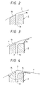
- the application head 3 and the web 1 are separated from each other as shown in Figure 1.
- liquid 2 is supplied into the slot 3a of the head.
- the changeover valve 25 or the pump 21 is then manipulated to stop sending the liquid to the head, and the position changers 6, 12 and 13 are, thereafter, appropriately operated to place the web and the head proximate each other, as shown in Figure 2.
- the web is positioned near the back edge portion 15 of the head or in slip contact therewith, the liquid 2 is thereafter sent to the head and discharged from the slot 3a thereof as shown in Figure 3, and the web is subsequently lapped with the doctor edge portion 16 of the head, which is located downstream of the slot, so that a desired lap angle ⁇ is set for the application, as shown in Figure 4.
- the upstream path roller 7 provided upstream of the head with regard to the direction of the running of the web, is moved relative to the back edge portion in the direction of the thickness of the web by the roller position changer 13 so that the web and the back edge portion are positioned relative to each other.
- the liquid 2 is discharged from the slot 3a of the head 3.
- the head is thereafter moved straight toward the web 1 by the head position change 6 so that the web and the doctor edge portion 16 of the head are positioned adjacent each other.
- the positional relationship between the head 3 and each of the path rollers 7 and 8 is sent in advance.
- the liquid 2 is discharged from the slot 3a of the head, and the downstream path roller 8 is thereafter moved relative to the doctor edge portion in the direction of the thickness of the web by the roller positioned changer 12 so that the web and the doctor edge portion are positioned relative to each other to set the desired lap angle ⁇ for the application, as illustrated in Figure 4.
- the liquid 2 is applied to the surface of the web 1. Since the web 1 and the back edge portion 15 of the head 3 come into contact with each other at the beginning of the application, scraped chips are removed from the web at the initial stage of contact so that the chips are moved downstream, due to the flow of the liquid. More specifically, since the web 1 is not lapped with all the web-facing surface of the edge part of the head 3 at the initial stage of the contact and the time of the contact is very short, the scraped chips are not trapped at the upstream edge of the doctor edge portion 16 of the head, so that streaks are prevented from being formed on the film of liquid 2.
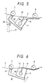
- both the application head 3 and the path rollers 7 and 8 can be translated in the application device shown in Figure 1, the present invention is not confined thereto but may be otherwise embodied as described with reference to Figure 5 and 6 from now on.
- the positions of path rollers 7 and 8 are fixed, and an application head 3 is supported by a pivot arm 30 which is pivotable about a fulcrum 31 in the direction of the arrows in Figures 5 and 6.
- the application head 3 is initially rotated by a prescribed angle ⁇ from a displaced position so as to place the back edge portion 15 of the head near the web or in slip contact therewith.
- the liquid 2 is thereafter discharged from the slot 3a of the head, and the head is then rotated further so as to lap the web with the doctor edge portion 16 of the head at a lap angle for the application. Since the head 3 is thus swung with the arm 30, the application device is not only relatively simple but also the fulcrum 31 can be located near the place of contact of the web 1 and a path roller 7 so as to keep the angle of the approaching web 1 with respect to the back edge portion 15 of the head constant at the time of rotating the head with the arm.
- an extrusion-type application head faces the surface of a flexible band-like carrier being continuously conveyed by path rollers, so that when the application of a liquid to the carrier is to be started or resumed, the carrier is placed near the back edge portion of the head or in slip contact therewith. Thereafter, the liquid is discharged from the slot of the head, and the carrier and the doctor edge portion of the head, which is located downstream of the slot, are then lapped with each other at a prescribed lap angle for the subsequent application. For that reason, scraped chips, created by contact between the carrier and the back edge portion of the head at the beginning or resumption of the application, are moved downstream due to the flow of the liquid.
- the scraped chips are not trapped at the upstream edge of the doctor edge portion of the head because the carrier is not lapped with all the carrier-facing surface of the edge part of the head at the initial stage of the contact, at which the scraped chips are made, and the contact time is very short. Further, even if the chips become trapped at the upstream edge of the doctor edge portion of the head at the initial stage of the contact, the chips would altogether move downstream by the flow of the liquid when the liquid was discharged from the slot of the head. As a result, there are no resulting streaks which would otherwise form on the film of the applied liquid on the carrier due to the scraped chip at the beginning or resumption of the application.
- streaking and scraping can be significantly reduced to stably manufacture a high-quality magnetic recording medium of good electromagnetic converting property with high yield and productivity.
- the application device which is shown in Figure 1, in which the application head 3 and the path rollers 7 and 8 are movable and the position changers 6, 12 and 13 are hydraulic cylinders, was used to perform application in the method described above. Substances shown in Table 1 were put in a ball mill so that the substances were well mixed and dispersed together. Thirty parts by weight of an epoxy resin of 500 in epoxy equivalent were added to the mixture and uniformly mixed and dispersed therewith so that a magnetic liquid was manufactured.
- the magnetic liquid was applied to a carrier made of a polyethylene terephthalate film.
- Table 2 shows the factors for the application.
- the carrier 1 was moved toward the back edge portion of the application head 3.
- the magnetic liquid was thereafter discharged from the slot of the head.
- the carrier 1 and the doctor edge portion of the head 3 were then lapped with each other at the lap angle for the application.
- the application was started.
- the application was stopped and then resumed.
- the application, the stoppage thereof and the resumption thereof were repeated.
- the movement of the application head 3 and the path rollers 7 and 8 was detected by the limit switches.
- the changeover valve 25 was opened so that the magnetic liquid was sent to the application head 3.
- Table 3 shows the result of the inspection.
Landscapes
- Application Of Or Painting With Fluid Materials (AREA)
- Coating Apparatus (AREA)
Claims (8)
- Procédé d'application dans lequel un liquide (2) devant être appliqué sort en continu d'une fente (3a) d'une tête d'application du type à extrusion (3) ayant une partie de bord arrière (15) et une partie de bord de raclage (16) qui font toutes deux face à la surface d'un support flexible en forme de bande (1) qui est transporté en continu tout en étant supporté par des rouleaux de défilement (7, 8) de telle sorte qu'un film mince de liquide est appliqué sur ladite surface, ladite partie de bord de raclage se trouvant en aval de ladite fente (3a) par rapport à la direction de transport dudit support,
caractérisé par
les étapes suivantes avant ladite application de liquide sur ladite surface,(a) positionnement dudit support (1) et de ladite partie de bord arrière (15) de telle sorte que les deux sont dirigés l'un vers l'autre, ou que les deux sont en contact de glissement l'un avec l'autre.(b) début de l'évacuation du liquide (2) de ladite fente (3a), et(c) positionnement dudit support (1) et de ladite partie de bord de raclage (16) de telle sorte que ladite partie de bord de raclage est dirigée vers ledit support, et qu'un angle prescrit (α) est formé entre la partie du support qui est dirigée vers ladite partie de bord arrière (15) et la partie du support qui est dirigée vers ladite partie de bord de raclage pour ladite application, afin que ledit support et ladite partie de bord de raclage se chevauchent. - Procédé selon la revendication 1, dans lequel l'étape (a) est réalisée en déplaçant le rouleau de défilement (7) disposé en amont de la tête (3) par rapport à la direction de transport dudit support par rapport à ladite partie de bord arrière (15) dans le sens de l'épaisseur dudit support (1) de telle sorte qu'un angle prescrit entre le support et la partie de bord arrière est ajusté, et
ladite tête est déplacée vers ledit support, après ledit démarrage de l'évacuation de liquide. - Procédé selon les revendications 1 ou 2, dans lequel l'étape (c) est réalisée en déplaçant le rouleau de défilement (8) qui se trouve en aval de ladite tête (3) par rapport à la direction de transport du support par rapport à ladite partie de bord de raclage (16) dans le sens de l'épaisseur dudit support (1) de telle sorte qu'un angle prescrit entre le support et la partie de bord de raclage est établi.
- Procédé selon la revendication 1, dans lequel l'étape (a) est réalisée en faisant tourner ladite tête (3) suivant un premier angle prescrit (β) et
l'étape (c) est réalisée en faisant tourner ladite tête (3) suivant un deuxième angle prescrit. - Appareil destiné à appliquer un liquide (2) sur un support flexible en forme de bande transporté en continu (1) comportant une tête d'application (3) ayant une partie de bord arrière (15), une partie de bord de raclage (16) et une fente (3a) disposée dedans, ladite tête (3) faisant face audit support (1), ladite partie de bord de raclage se trouvant en aval de ladite fente (3a) par rapport à la direction de transport dudit support, des moyens (21, 22, 25, 23) destinés à évacuer ledit liquide (2) de ladite fente (3a), des moyens destinés à positionner ledit support par rapport à ladite tête,
caractérisé en ce que
lesdits moyens de positionnement comportent des premiers moyens (6, 13; 31) destinés à positionner ledit support (1) et ladite partie de bord arrière (15) de telle sorte que les deux sont dirigés l'un vers l'autre, ou sont en contact de glissement l'un avec l'autre, et des seconds moyens (8, 12, 31) destinés à positionner ledit support (1) par rapport à ladite partie de bord de raclage (16) de telle sorte que les deux sont dirigés l'un vers l'autre, et en ce qu'un angle prescrit (α) est formé entre la partie du support qui est dirigée vers ladite partie de bord arrière (15) et la partie du support qui fait face à ladite partie de bord de raclage (16) afin que ledit support et ladite partie de bord de raclage se chevauchent. - Appareil selon la revendication 5, dans lequel lesdits premiers moyens comportent
des moyens (6) destinés à déplacer ladite tête (3) vers ledit support (1),
un rouleau de défilement (7) disposé en amont de ladite tête (3) par rapport à ladite direction de transport dudit support, et
des moyens (13) destinés à déplacer ledit rouleau de défilement (7) dans le sens de l'épaisseur dudit support de telle sorte qu'un angle prescrit entre le support et la partie de bras arrière est ajusté. - Appareil selon la revendication 5 ou 6, dans lequel lesdits deuxièmes moyens comportent
un rouleau de défilement (8) qui se trouve en aval de ladite tête (3) par rapport à ladite direction de transport dudit support, et
des moyens (12) destinés à déplacer le rouleau de défilement (8) dans le sens de l'épaisseur dudit support de telle sorte qu'un angle prescrit entre le support et la partie de bord de raclage est établi. - Appareil selon la revendication 5, dans lequel lesdits premiers moyens comportent des moyens (31) destinés à faire tourner ladite tête suivant un premier angle prescrit (β) de telle sorte que ledit support et ladite partie de bord arrière sont dirigés l'un vers l'autre, ou sont en contact de glissement l'un avec l'autre,
lesdits deuxièmes moyens comportent des moyens (31) destinés à faire tourner ladite tête suivant un deuxième angle prescrit.
Applications Claiming Priority (2)
| Application Number | Priority Date | Filing Date | Title |
|---|---|---|---|
| JP96285/90 | 1990-04-13 | ||
| JP2096285A JP2601365B2 (ja) | 1990-04-13 | 1990-04-13 | 塗布方法 |
Publications (3)
| Publication Number | Publication Date |
|---|---|
| EP0451863A2 EP0451863A2 (fr) | 1991-10-16 |
| EP0451863A3 EP0451863A3 (en) | 1991-12-18 |
| EP0451863B1 true EP0451863B1 (fr) | 1995-12-20 |
Family
ID=14160834
Family Applications (1)
| Application Number | Title | Priority Date | Filing Date |
|---|---|---|---|
| EP91105871A Expired - Lifetime EP0451863B1 (fr) | 1990-04-13 | 1991-04-12 | Procédé d'application d'un liquide sur un substrat flexible |
Country Status (4)
| Country | Link |
|---|---|
| US (2) | US5202164A (fr) |
| EP (1) | EP0451863B1 (fr) |
| JP (1) | JP2601365B2 (fr) |
| DE (1) | DE69115545T2 (fr) |
Cited By (1)
| Publication number | Priority date | Publication date | Assignee | Title |
|---|---|---|---|---|
| CN102935413A (zh) * | 2012-11-19 | 2013-02-20 | 深圳市信宇人科技有限公司 | 间歇式挤压涂布方法、挤压涂布头及挤压涂布机 |
Families Citing this family (23)
| Publication number | Priority date | Publication date | Assignee | Title |
|---|---|---|---|---|
| FI93884C (fi) * | 1992-04-10 | 1995-06-12 | Valmet Paper Machinery Inc | Applikointipalkki liimapuristimessa |
| JP2916557B2 (ja) * | 1992-04-16 | 1999-07-05 | 富士写真フイルム株式会社 | 塗布装置 |
| DE4226139A1 (de) * | 1992-08-07 | 1994-02-10 | Basf Magnetics Gmbh | Vorrichtung zur Herstellung eines magnetischen Aufzeichnungsträgers |
| DE4234608C2 (de) * | 1992-08-07 | 1997-08-07 | Basf Magnetics Gmbh | Verfahren zur Herstellung eines magnetischen Aufzeichnungsträgers |
| JP3340768B2 (ja) * | 1992-09-17 | 2002-11-05 | ティーディーケイ株式会社 | 押出し塗布方法およびその装置 |
| JP3267782B2 (ja) * | 1993-12-28 | 2002-03-25 | ティーディーケイ株式会社 | 塗布方法 |
| FI100024B2 (fi) * | 1994-05-19 | 2003-02-04 | Valmet Corp | Menetelmä ja laite liiman tai vastaavan levittämiseksi liikkuvalle aineradalle |
| WO1996015860A1 (fr) * | 1994-11-23 | 1996-05-30 | Alcan International Limited | Machine a enduction directe pour bandes de metal allongees |
| JP3168388B2 (ja) * | 1994-12-26 | 2001-05-21 | 富士写真フイルム株式会社 | 塗布方法 |
| DE19504930A1 (de) * | 1995-02-15 | 1996-08-22 | Basf Magnetics Gmbh | Vorrichtung zur Herstellung eines magnetischen Aufzeichnungsträgers |
| JPH0975814A (ja) * | 1995-09-19 | 1997-03-25 | Fuji Photo Film Co Ltd | 塗布装置 |
| EP0774301A1 (fr) * | 1995-10-19 | 1997-05-21 | Minnesota Mining And Manufacturing Company | Dispositif pour enlever un produit de revêtement déposé sur une bande en mouvement et installation de revêtement utilisant à dispositif |
| EP0798054B1 (fr) * | 1996-02-28 | 2003-09-03 | Nippon Shokubai Co., Ltd. | Procédé pour fabriquer en continu un film revêtu |
| JP3254574B2 (ja) | 1996-08-30 | 2002-02-12 | 東京エレクトロン株式会社 | 塗布膜形成方法及びその装置 |
| DE29908150U1 (de) | 1999-05-10 | 1999-08-05 | Nordson Corporation, Westlake, Ohio | Vorrichtung zum Auftragen von Fluid |
| ITPS20000013A1 (it) * | 2000-09-05 | 2002-03-05 | Canti & Figli Srl | Procedimento e macchina per l'applicazione di uno spesso strato di vernice su fogli da nobilitazione in bobinr |
| JP2002163822A (ja) * | 2000-11-27 | 2002-06-07 | Fuji Photo Film Co Ltd | 磁気記録媒体及びその製造方法 |
| WO2004046835A2 (fr) * | 2002-11-15 | 2004-06-03 | Applied Materials, Inc. | Procede, systeme et support permettant de gerer un processus de fabrication a l'aide de parametres d'entree multidimensionnels |
| US20050233073A1 (en) * | 2004-04-19 | 2005-10-20 | The Procter & Gamble Company | Method and apparatus for applying coatings, for instance for sanitary products |
| EP2025412B1 (fr) * | 2007-08-17 | 2012-07-25 | Nordson Corporation | Distributeur de liquide avec buse de contact montée sur ressort |
| US20110256692A1 (en) * | 2010-04-14 | 2011-10-20 | Applied Materials, Inc. | Multiple precursor concentric delivery showerhead |
| CN106862010A (zh) * | 2017-03-24 | 2017-06-20 | 苏州威格尔纳米科技有限公司 | 一种旋转式狭缝涂布模头及方法 |
| WO2018236395A1 (fr) | 2017-06-23 | 2018-12-27 | Kimberly-Clark Worldwide, Inc. | Appareil et procédé pour appliquer un adhésif sur une bande en mouvement |
Family Cites Families (9)
| Publication number | Priority date | Publication date | Assignee | Title |
|---|---|---|---|---|
| US4068614A (en) * | 1976-05-07 | 1978-01-17 | Rothmans Of Pall Mall Canada Limited | Machine for applying liquid to absorbent material |
| US4386998A (en) * | 1979-08-27 | 1983-06-07 | Acumeter Laboratories, Inc. | Adhesive applicator and method for cigarette-to-filter adhesion and similar applications |
| JPS58104666A (ja) * | 1981-12-16 | 1983-06-22 | Fuji Photo Film Co Ltd | 塗布装置 |
| JPS60238179A (ja) * | 1984-05-14 | 1985-11-27 | Fuji Photo Film Co Ltd | 塗布装置 |
| JPH0691980B2 (ja) * | 1985-10-18 | 1994-11-16 | 富士写真フイルム株式会社 | 磁性液塗布方法及び装置 |
| JPH0640990B2 (ja) * | 1985-11-15 | 1994-06-01 | 富士写真フイルム株式会社 | 塗布方法 |
| JPH069670B2 (ja) * | 1986-01-16 | 1994-02-09 | 富士写真フイルム株式会社 | 塗布方法 |
| US4995338A (en) * | 1987-09-24 | 1991-02-26 | Honda Giken Kogyo Kabushiki Kaisha | Coating apparatus |
| JPH0824872B2 (ja) * | 1988-06-07 | 1996-03-13 | 松下電器産業株式会社 | 塗布装置 |
-
1990
- 1990-04-13 JP JP2096285A patent/JP2601365B2/ja not_active Expired - Fee Related
-
1991
- 1991-04-11 US US07/683,905 patent/US5202164A/en not_active Expired - Lifetime
- 1991-04-12 DE DE69115545T patent/DE69115545T2/de not_active Expired - Fee Related
- 1991-04-12 EP EP91105871A patent/EP0451863B1/fr not_active Expired - Lifetime
-
1992
- 1992-10-26 US US07/966,333 patent/US5614023A/en not_active Expired - Lifetime
Non-Patent Citations (1)
| Title |
|---|
| PATENT ABSTRACTS OF JAPAN vol. 11, no. 307 (C-450) October 7, 1987 & JP-A-62 95 169 (FUJI PHOTO FILM ) May 1, 1987 & JP-A-62 95 169 * |
Cited By (1)
| Publication number | Priority date | Publication date | Assignee | Title |
|---|---|---|---|---|
| CN102935413A (zh) * | 2012-11-19 | 2013-02-20 | 深圳市信宇人科技有限公司 | 间歇式挤压涂布方法、挤压涂布头及挤压涂布机 |
Also Published As
| Publication number | Publication date |
|---|---|
| EP0451863A2 (fr) | 1991-10-16 |
| US5614023A (en) | 1997-03-25 |
| US5202164A (en) | 1993-04-13 |
| DE69115545D1 (de) | 1996-02-01 |
| DE69115545T2 (de) | 1996-05-02 |
| JPH03296467A (ja) | 1991-12-27 |
| JP2601365B2 (ja) | 1997-04-16 |
| EP0451863A3 (en) | 1991-12-18 |
Similar Documents
| Publication | Publication Date | Title |
|---|---|---|
| EP0451863B1 (fr) | Procédé d'application d'un liquide sur un substrat flexible | |
| KR101420882B1 (ko) | 간헐 도포 방법 및 간헐 도포 장치 | |
| CA2039879A1 (fr) | Methode et appareil permettant d'appliquer une couche de materiau fluide sur une plaquette a semi-conducteurs | |
| US4831961A (en) | Magnetic liquid application method and apparatus | |
| JPS6380872A (ja) | 塗布方法及び装置 | |
| JPS62201669A (ja) | ロ−ルコ−タの制御方法およびロ−ルコ−タ | |
| US4310576A (en) | Adhesive-applying apparatus and method | |
| US6387455B1 (en) | Coating method and apparatus including an air shielding device | |
| US6086954A (en) | Method and apparatus for application of coating medium onto a traveling material web having a splice | |
| EP0714325B1 (fr) | Applicateur de couche de revetement a rouleau pourvu d'une raclette, a alimentation par corps de filiere, sans recirculation du fluide et avec addition de solvant | |
| KR100486127B1 (ko) | 약액도포방법 및 그 도포장치 | |
| EP0774301A1 (fr) | Dispositif pour enlever un produit de revêtement déposé sur une bande en mouvement et installation de revêtement utilisant à dispositif | |
| EP0530751A1 (fr) | Appareil et méthode d'enduction | |
| US4889072A (en) | Coating apparatus | |
| US6436465B1 (en) | Extrusion coating method | |
| JPH09141174A (ja) | 塗布装置及び塗布方法 | |
| JPH08173877A (ja) | 塗布方法及び塗布装置 | |
| JP4407533B2 (ja) | 塗布方法 | |
| EP0650769B1 (fr) | Configuration de filière d'enduction en forme de fente | |
| JP3002358B2 (ja) | ローラーカーテンコータ装置 | |
| JPH067815Y2 (ja) | 塗布装置 | |
| JPH06277613A (ja) | ブレードコーターの塗工方法と塗工装置 | |
| JP3105161B2 (ja) | 塗布装置 | |
| JP2855032B2 (ja) | 塗布方法及び装置 | |
| JPH07108213A (ja) | 塗布方法 |
Legal Events
| Date | Code | Title | Description |
|---|---|---|---|
| PUAI | Public reference made under article 153(3) epc to a published international application that has entered the european phase |
Free format text: ORIGINAL CODE: 0009012 |
|
| AK | Designated contracting states |
Kind code of ref document: A2 Designated state(s): DE FR NL |
|
| PUAL | Search report despatched |
Free format text: ORIGINAL CODE: 0009013 |
|
| AK | Designated contracting states |
Kind code of ref document: A3 Designated state(s): DE FR NL |
|
| 17P | Request for examination filed |
Effective date: 19920218 |
|
| 17Q | First examination report despatched |
Effective date: 19940712 |
|
| GRAA | (expected) grant |
Free format text: ORIGINAL CODE: 0009210 |
|
| AK | Designated contracting states |
Kind code of ref document: B1 Designated state(s): DE FR NL |
|
| PG25 | Lapsed in a contracting state [announced via postgrant information from national office to epo] |
Ref country code: NL Free format text: LAPSE BECAUSE OF FAILURE TO SUBMIT A TRANSLATION OF THE DESCRIPTION OR TO PAY THE FEE WITHIN THE PRESCRIBED TIME-LIMIT Effective date: 19951220 |
|
| REF | Corresponds to: |
Ref document number: 69115545 Country of ref document: DE Date of ref document: 19960201 |
|
| ET | Fr: translation filed | ||
| NLV1 | Nl: lapsed or annulled due to failure to fulfill the requirements of art. 29p and 29m of the patents act | ||
| PLBE | No opposition filed within time limit |
Free format text: ORIGINAL CODE: 0009261 |
|
| STAA | Information on the status of an ep patent application or granted ep patent |
Free format text: STATUS: NO OPPOSITION FILED WITHIN TIME LIMIT |
|
| 26N | No opposition filed | ||
| REG | Reference to a national code |
Ref country code: FR Ref legal event code: TP Ref country code: FR Ref legal event code: CD |
|
| PGFP | Annual fee paid to national office [announced via postgrant information from national office to epo] |
Ref country code: DE Payment date: 20080417 Year of fee payment: 18 Ref country code: FR Payment date: 20080312 Year of fee payment: 18 |
|
| REG | Reference to a national code |
Ref country code: FR Ref legal event code: ST Effective date: 20091231 |
|
| PG25 | Lapsed in a contracting state [announced via postgrant information from national office to epo] |
Ref country code: DE Free format text: LAPSE BECAUSE OF NON-PAYMENT OF DUE FEES Effective date: 20091103 |
|
| PG25 | Lapsed in a contracting state [announced via postgrant information from national office to epo] |
Ref country code: FR Free format text: LAPSE BECAUSE OF NON-PAYMENT OF DUE FEES Effective date: 20091222 |