EP0452493A1 - Prozessgas-zufuhranordnung - Google Patents
Prozessgas-zufuhranordnung Download PDFInfo
- Publication number
- EP0452493A1 EP0452493A1 EP90900358A EP90900358A EP0452493A1 EP 0452493 A1 EP0452493 A1 EP 0452493A1 EP 90900358 A EP90900358 A EP 90900358A EP 90900358 A EP90900358 A EP 90900358A EP 0452493 A1 EP0452493 A1 EP 0452493A1
- Authority
- EP
- European Patent Office
- Prior art keywords
- process gas
- gas
- aforesaid
- passive state
- gas feeder
- Prior art date
- Legal status (The legal status is an assumption and is not a legal conclusion. Google has not performed a legal analysis and makes no representation as to the accuracy of the status listed.)
- Withdrawn
Links
Images


Classifications
-
- C—CHEMISTRY; METALLURGY
- C23—COATING METALLIC MATERIAL; COATING MATERIAL WITH METALLIC MATERIAL; CHEMICAL SURFACE TREATMENT; DIFFUSION TREATMENT OF METALLIC MATERIAL; COATING BY VACUUM EVAPORATION, BY SPUTTERING, BY ION IMPLANTATION OR BY CHEMICAL VAPOUR DEPOSITION, IN GENERAL; INHIBITING CORROSION OF METALLIC MATERIAL OR INCRUSTATION IN GENERAL
- C23C—COATING METALLIC MATERIAL; COATING MATERIAL WITH METALLIC MATERIAL; SURFACE TREATMENT OF METALLIC MATERIAL BY DIFFUSION INTO THE SURFACE, BY CHEMICAL CONVERSION OR SUBSTITUTION; COATING BY VACUUM EVAPORATION, BY SPUTTERING, BY ION IMPLANTATION OR BY CHEMICAL VAPOUR DEPOSITION, IN GENERAL
- C23C16/00—Chemical coating by decomposition of gaseous compounds, without leaving reaction products of surface material in the coating, i.e. chemical vapour deposition [CVD] processes
- C23C16/44—Chemical coating by decomposition of gaseous compounds, without leaving reaction products of surface material in the coating, i.e. chemical vapour deposition [CVD] processes characterised by the method of coating
- C23C16/4401—Means for minimising impurities, e.g. dust, moisture or residual gas, in the reaction chamber
- C23C16/4402—Reduction of impurities in the source gas
-
- C—CHEMISTRY; METALLURGY
- C23—COATING METALLIC MATERIAL; COATING MATERIAL WITH METALLIC MATERIAL; CHEMICAL SURFACE TREATMENT; DIFFUSION TREATMENT OF METALLIC MATERIAL; COATING BY VACUUM EVAPORATION, BY SPUTTERING, BY ION IMPLANTATION OR BY CHEMICAL VAPOUR DEPOSITION, IN GENERAL; INHIBITING CORROSION OF METALLIC MATERIAL OR INCRUSTATION IN GENERAL
- C23C—COATING METALLIC MATERIAL; COATING MATERIAL WITH METALLIC MATERIAL; SURFACE TREATMENT OF METALLIC MATERIAL BY DIFFUSION INTO THE SURFACE, BY CHEMICAL CONVERSION OR SUBSTITUTION; COATING BY VACUUM EVAPORATION, BY SPUTTERING, BY ION IMPLANTATION OR BY CHEMICAL VAPOUR DEPOSITION, IN GENERAL
- C23C14/00—Coating by vacuum evaporation, by sputtering or by ion implantation of the coating forming material
- C23C14/22—Coating by vacuum evaporation, by sputtering or by ion implantation of the coating forming material characterised by the process of coating
- C23C14/56—Apparatus specially adapted for continuous coating; Arrangements for maintaining the vacuum, e.g. vacuum locks
- C23C14/564—Means for minimising impurities in the coating chamber such as dust, moisture, residual gases
-
- C—CHEMISTRY; METALLURGY
- C23—COATING METALLIC MATERIAL; COATING MATERIAL WITH METALLIC MATERIAL; CHEMICAL SURFACE TREATMENT; DIFFUSION TREATMENT OF METALLIC MATERIAL; COATING BY VACUUM EVAPORATION, BY SPUTTERING, BY ION IMPLANTATION OR BY CHEMICAL VAPOUR DEPOSITION, IN GENERAL; INHIBITING CORROSION OF METALLIC MATERIAL OR INCRUSTATION IN GENERAL
- C23C—COATING METALLIC MATERIAL; COATING MATERIAL WITH METALLIC MATERIAL; SURFACE TREATMENT OF METALLIC MATERIAL BY DIFFUSION INTO THE SURFACE, BY CHEMICAL CONVERSION OR SUBSTITUTION; COATING BY VACUUM EVAPORATION, BY SPUTTERING, BY ION IMPLANTATION OR BY CHEMICAL VAPOUR DEPOSITION, IN GENERAL
- C23C16/00—Chemical coating by decomposition of gaseous compounds, without leaving reaction products of surface material in the coating, i.e. chemical vapour deposition [CVD] processes
- C23C16/44—Chemical coating by decomposition of gaseous compounds, without leaving reaction products of surface material in the coating, i.e. chemical vapour deposition [CVD] processes characterised by the method of coating
- C23C16/4401—Means for minimising impurities, e.g. dust, moisture or residual gas, in the reaction chamber
- C23C16/4404—Coatings or surface treatment on the inside of the reaction chamber or on parts thereof
Definitions
- This invention relates to a process gas feeder suited to, for instance, formation of a various types of thin film or a fine pattern dry etching process, and particularly to a process gas feeder which allows formation of high quality films and high quality etching.
- This type of semiconductor devices are produced by repeating such processes as forming a thin film or etching a specified circuit pattern. And, generally this type of process is performed by putting a silicon wafer in a reaction chamber into which a specified gas is introduced under depressurised atmosphere. Depressurization is made to etch a through-hole or a contact hole with an aspect ratio, to make longer an average free travel of gas molecules, and to promote surface reaction and suppress gaseous reaction.
- Gases used in a semiconductor manufacturing system include general gases (N2,Ar,He,O2,H2) which are relatively stable, and specific material gases (AsH3,PH3, SiH4,Si2H6,HCl,NH3,Cl2,CF4,SF8,NF3,WH6, etc.) which have such characteristics as high toxicity, self-combustibility, and corrosiveness.
- the purge gas supply line can always be purged, and contamination by invasion of air into the piping system or release of gasses containing moisture from the inner surface of the piping material, so that now it is possible to supply a ultra-high purity gas.
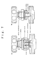
- a valve as described in Fig.7 (b) is used as for components of the above-described piping system wherein influence of released gasses is minimized.
- organic material such as resin is used for the valve seat (seat section) to improve its sealing capability.
- This invention was made to solve the problems as described above, and the purpose is to provide a gas feeder which does not release gasses giving bad effects to processes, in which moisture or any organic material commits, in a gas feeding system from a cylinder cabinet to a processing system almost at all.
- Essence of this invention consists in a process gas feeder characterized in that gas contacting sections of all gas feeding components constituting the aforesaid gas feeder are made of materials not containing any organic material to prevent contamination of inside of the gas feed piping system by gasses released from any organic material.
- the gas feed components include, for instance, a cylinder, a piping, a valve, a regulator, and a filter.
- metallic or ceramic materials for instance, stainless steel or that with a passive state film on its surface is preferred.
- a passive state film 1) a passive film comprising 2 or more layers including a layer formed close to an interface between the stainless steel layer and the passive state film and made of mainly chrome oxide and a layer formed close to a surface of the passive state film and made of mainly iron oxide, 2) a passive state film consisting of a layer made of mainly mixture of chrome oxide and iron oxide, and 3) a passive state film consisting of a layer made of mainly chrome oxide are preferred.
- a passive state film with a thickness of 100 ⁇ or more formed by heating and oxidizing stainless steel under a temperature in a range from 400 °C to 550 °C in case of 1), a passive state film with a thickness of 100 ⁇ or more formed by heating and oxidizing stainless steel for less than 9 hours under a temperature of 550°C or more in case of 2), and a passive state film with a thickness of 130 ⁇ or more formed by heating and oxidizing stainless steel for 9 hours or more under a temperature of 550 °C or more are preferred because of their excellent corrosion resistance and their capability to prevent release of moisture (the moisture release rate in these passive state films is one tenth or below of that in a passive state film formed using nitric acid). Note that it is preferred to form these passive state films in oxygen atmosphere with a moisture content of 10 ppb or below (more preferably 1 ppb or below).
- the maximum value in difference of height between a convex section and a concave section within a circle having a radius of 5 ⁇ m is 1 ⁇ m or below (preferably 0.1 to 1 ⁇ m) (mirror-like finishing).
- the leak rate can be suppressed to a level of 1 x 10 ⁇ 11 Torr ⁇ 1/sec or below.
- a gas feed piping system is characterized in that organic materials such as resin are eliminated from all gas-contacting sections of all piping components including valves, regulators, and filters and all of them are made of metallic or ceramic materials. Furthermore, the gas feed piping system is characterized in that influence by gasses released from organic materials used in the aforesaid gas-contacting sections are completely eliminated and bad effects such as corrosion due to moisture contained in the organic materials are removed.
- These types of resin are made of organic materials, absorb moisture, and contain unconverted organic materials, so that, when a gas is flown in an piping component using resin in the gas-contacting section therein, moisture or organic materials contained in the resin are released and a process gas to be fed to a processing system is contaminated.
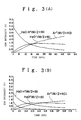
- Fig. 3 shows change of moisture content in a purge gas when a metallic diaphragm valve having a seat section made of different materials is purged under the room temperature.
- Ar gas was fed to a metal diaphragm valve at a flow rate of 1.2 l/min, and moisture content in the Ar gas at the exist was measured by an APIMS (Atmospheric pressure ionization mass spectrometer). Also Fig.
- the percentage of increase or decrease of ion intensity completely depends on the moisture content. In either case, measurement was started in 2 minutes after the sample was placed.
- Types of the tested metal diaphragm valve are as shown below.
- Fig. 3 consists of graphs A,B,C, and D. Each metal diaphragm valve was left for about 1 week in a clean room under a relative humidity of 50% and a temperature of 20°C , and then this experiment was made.
- valve D As shown in Fig. 3 A,B and C, in any of the valve A the valve B with a minimized dead space, and the valve C with the resin section coated with metal, a large volume of moisture was detected. Even after the gas was fed for about 1 hour, moisture was detected at an order of about 200 ppb in A and B, and at an order of 150 ppb in C, which indicates that reduction of moisture is very hard. In contract, in the valve D wherein resin was eliminated from the gas-contacting section, the moisture contents dropped to 16 ppb after the gas was fed for 1 hour. Thus, the valve D is more excellent in its capability to remove moisture by one order or more than the valves A,B and C, and has extremely excellent absorbed gas degassing characteristics. Fig.
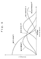
- Fig. 6 is also a simple graph illustrating behaviors f moisture in the APIMS.
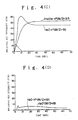
- valve A As clearly shown in Fig.4, A,B and C, a large quantity of moisture was detected in any of the valve A, the valve B with a minimized dead space, and the valve C with the resin section coated with metallic material.
- moisture was released at an order of several thousands ppb in about 15 minutes after heating was started, and this state was kept after heating was continued for 1 hours. In other words, release of moisture was continued everlastingly.
- the moisture release rate after heating was started was 100 ppb or less, indicating that the moisture release rate was largely ( by max. 2 digits) smaller than those in other valves.
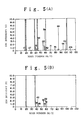
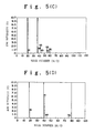
- Fig. 5 shows representative spectrums during heating, and A,B, C and D correspond to those in Fig. 4 respectively.
- A,B and C not only a peak of the host gas (Argon) disappeared due to influence by a quantity of released moisture, but also materials with the mass number (M/Z) of 43,45,59,61 and 71, which could be regarded as organic materials, were detected.
- M/Z mass number of 43,45,59,61 and 71, which could be regarded as organic materials
- the valve D not using any organic material in the gas-contacting section, not only the moisture release rate was low, but also release of organic materials giving bad effects to the semiconductor manufacturing process was not observed.
- a ceramic filter using ceramics, which is in-organic material, in its elements has been developed, and a nickel packing is available for the gasket, so that resin, an organic material conventionally used, can be removed from its gas-contacting section.
- the elements can be made of stainless and their connection to the housing may be made by means of welding, so that an all-metal filter completely made of stainless steel is available.
- release of gas from seat sections or other gas-contacting sections can be suppressed by eliminating all organic materials from gas-contacting sections in a gas feed system and using metal or ceramics in place of the organic materials in the sections.
- gas-contacting sections can be passivated to a metallic one having excellent degassing and corrosion-resistant characteristics, so that it is possible to feed a ultra-high purity gas containing impurities extremely little.
- no organic material is used in a gas feed system, so that a quantity of gasses released from a surface of the gas-contacting section is reduced and a ultra-high vacuum and extremely clean depressurizing system as well as a gas feed system having excellent corrosion resistance against reactive and corrosive gasses can be obtained.
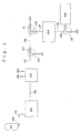
- Fig. 1 is a system diagram of an embodiment 1 ( Liquified gas storage tank - Refining tank - Process system ) of a piping system including no organic material in gas-contacting sections in a process gas feed system according to this invention.
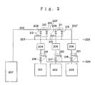
- Fig. 2 is a system diagram of an embodiment 2 (Cylinder cabinet - Process system ) of a piping system including no organic material in gas-contacting sections in a process gas feed system according to this invention.
- Fig. 3 is a graph showing difference in gas release characteristics under the room temperature between a valve having organic materials in the gas-contacting sections and a valve having no organic materials in the gas-contacting sections.
- Fig. 4 is a graph showing difference in gas release characteristics under a high temperature (130 °C) between a valve having organic materials in the gas-contacting sections and a valve having no organic material in the gas-contacting section.
- Fig. 5 is a graph showing representative spectrums under a high temperature.
- Fig. 6 is a drawing illustrating how to see data provided by an APIMS (Atmospheric pressure ion mass spectrometer), which is a graph simply showing behaviors of host gas (Argon) ions and water ions associated with change of the moisture quantity.
- APIMS atmospheric pressure ion mass spectrometer
- Fig. 7 is a cross section of an example of a valve.
- 101 is a liquified gas storage tank
- 102 is a gas refining system
- 103 is a valve port
- 104 is a control unit
- 105 is a processing system
- 106,107,108,109,110,111 and 112 are stop valves
- 113,114,115,116,117,118,119,120,121 and 122 are process gas feed pipes
- 123 is a gas discharge line
- 201,202 and 203 are processing systems
- 204,205 and 206 are control units
- 207 is a cylinder cabinet piping system
- 208,209,210,211,212,213,214,215,216,217,218,219,220 and 221 are stop valves
- 222,222' and 222'' are process gas feed lines
- 223 is a purge gas feed line
- 224 and 225 are purge gas discharge lines.
- Fig.1 is a schematic drawing of an example of piping system in an embodiment of a gas feed system according to this invention.
- 101 is a system comprising a liquified gas storage tank and an carburetor, which stores liquified gas produced by a liquified gas producing system such as nitrogen gas, oxygen gas, and argon gas, and sends the gas to a processing system or other systems.
- a liquified gas producing system such as nitrogen gas, oxygen gas, and argon gas
- electrolytic polishing was applied to the inner surface to eliminate generation of particles and minimize release of gasses.
- 101 may be a liquified gas producing system (on-site plant).
- 102 is a gas refining system, which refines gas fed from 101 and feeds high purity gas to the processing system.
- equipment constituting this system may vary according to a type of gas to be fed, and generally there are may valves and filters at an exit of a refining system. It is needless to say that the components do not include any organic material in their gas-contacting sections, and any organic material is not included in gas-contacting sections of piping components before the above components, neither;
- a valve port which feeds ultra-high purity gas fed from the refining system 102 to multiple units of processing system.
- Fig. 1 shows a one gas feed line branched to 3 lines, generally a feed line comprises 3 to 5 lines, while a branch line comprises 2 to 4 lines, so that multiple types of gas can be fed to the processing systems.
- control unit 104 is a control unit which regulates pressure and flow rate of gas to be fed to a processing system, and generally comprises a mass flow controller, a filter, valves, and a regulator.
- 107,108,109,110,111 and 112 are stop valves, 107 and 110, 108 and 111, and 109 and 112 are two-throw three-directional valves wherein 2 valves are integrated respectively, and each of the two-throw three-directional valves branches the gas feed piping system. Electrolytic polishing is applied to inner surfaces of these component to eliminate leakage to outside and minimize release of gasses, and no organic material is included in the gas-contacting sections.
- 113,114,115,116,117 and 118 are piping linking each system, and generally stainless steel pipes with the thickness from 1/4" to 1/2" are used.
- SUS 316 L pipe with inner surface electrolytically polished is used to eliminate particles and minimize release of gasses.
- 105 is a process chamber, and 106 is a stop valve.
- 119 and 120 branch lines from the valve port 103, 121 and 122 are branch lines from the pipes 115 and 116, which feed gas to each processing system.
- 123 is a discharge line for gas to be fed to the chamber 105, which discharge gas to outdoors by making an appropriate processing such as feeding into a discharge gas processing system according to a type of the gas.
- the above-described process gas feed line was completely made of metallic materials and a processing for metal passivation could be made to feed further higher purity process gas.
- a stainless passive state film obtained by processing for 5 to 10 hours in ultra-high purity oxygen (with the moisture contents of around 10 ppb or less) under a temperature of 500 °C not only did not absorb moisture almost at all with a little adhesion, and the adhered moisture could easily be removed.
- a passive state film by heating under a temperature from not less than 400 °C to less than 550 °C or under a temperature of not less than 550 °C for less than 9 hours, and preferably by heating under a temperature of not less than 550 °C for less than 9 hours, but also in case of a passive state film formed in ultra-high purity oxygen (with the expediities content of less than 1 ppb) under a temperature from 200 to 250 °C, good results were obtained.
- a passive state film obtained through this type of passivation is an amorphous film such as Fe2O3 or Cr2O3, and is defined as a ceramic material in abroad sense in this invention.
- Fig.2 is a piping diagram for a gas feed system in the other embodiment of this invention, showing an example of piping for feeding gas stored in a cylinder to a cylinder cabinet to a processing system.
- 3 units of processing system are units, but only on process gas feed line is drawing in the figure to simplify the illustration.
- 201, 202 and 203 are processing systems.
- 204, 205 and 206 are control units which regulate pressure for feeding gasses and their flow rates, which are the equivalent to 104 in Fig.1.
- 207 is a cylinder cabinet piping system to stores a process gas cylinder and feeds process gas.
- 208,209,210,211,212,213,214,215,216,217,218,219,220 and 221 are stop valves.
- 208 and 210,212 and 214, 209 and 211, and 213 and 215 are mono-block valves, in each of which 4 pieces of valves are integrated respectively to minimize the gas resident section.
- 216 and 219,217 and 220, and 218 and 221 are two-throw three-directional valves, in each of which 2 pieces of valves are integrated. All components used in these 204,205,206,207,208,209,210,211,212,213,214,215,216,218,219, 220 and 221 are mode of materials not containing any organic material in their gas-contacting sections.
- 222,222' and 222'' are process gas feed pipe lines
- 223 is a feed line for purge gas such as argon
- 224 and 225 are purge gas discharge lines, and each of these lines generally comprises SUS 316 L pipes with the inner surfaces electrolytically polished having a thickness of 1/4" to 3/8". Note that, as all of the above-described process gas feed lines can be made of metallic materials, the metallic materials can be passivated, thus further higher purity process gas being fed.
Landscapes
- Chemical & Material Sciences (AREA)
- Metallurgy (AREA)
- Chemical Kinetics & Catalysis (AREA)
- Engineering & Computer Science (AREA)
- Materials Engineering (AREA)
- Mechanical Engineering (AREA)
- Organic Chemistry (AREA)
- General Chemical & Material Sciences (AREA)
- Pipeline Systems (AREA)
- Filling Or Discharging Of Gas Storage Vessels (AREA)
- Chemical Vapour Deposition (AREA)
- ing And Chemical Polishing (AREA)
- Drying Of Semiconductors (AREA)
- Feeding, Discharge, Calcimining, Fusing, And Gas-Generation Devices (AREA)
- Physical Vapour Deposition (AREA)
Applications Claiming Priority (2)
| Application Number | Priority Date | Filing Date | Title |
|---|---|---|---|
| JP33535488A JPH02179867A (ja) | 1988-12-29 | 1988-12-29 | プロセスガス供給システム |
| JP335354/88 | 1988-12-29 |
Publications (2)
| Publication Number | Publication Date |
|---|---|
| EP0452493A1 true EP0452493A1 (de) | 1991-10-23 |
| EP0452493A4 EP0452493A4 (en) | 1992-02-26 |
Family
ID=18287592
Family Applications (1)
| Application Number | Title | Priority Date | Filing Date |
|---|---|---|---|
| EP19900900358 Withdrawn EP0452493A4 (en) | 1988-12-29 | 1989-12-26 | Feeder for process gas |
Country Status (3)
| Country | Link |
|---|---|
| EP (1) | EP0452493A4 (de) |
| JP (1) | JPH02179867A (de) |
| WO (1) | WO1990007587A1 (de) |
Cited By (2)
| Publication number | Priority date | Publication date | Assignee | Title |
|---|---|---|---|---|
| DE4242967A1 (de) * | 1992-12-18 | 1994-06-23 | Messer Griesheim Gmbh | Verfahren zum Spülen und Rekonditionieren von Transfersystemen |
| EP0949470A3 (de) * | 1998-04-07 | 1999-12-29 | L'air Liquide, Societe Anonyme Pour L'etude Et L'exploitation Des Procedes Georges Claude | System und Verfahren zur Abgabe eines dampfförmigen Produktes an einen Verwendungsort |
Families Citing this family (5)
| Publication number | Priority date | Publication date | Assignee | Title |
|---|---|---|---|---|
| JPH034928A (ja) * | 1989-05-31 | 1991-01-10 | Motoyama Seisakusho:Kk | ガス供給装置 |
| JP4159004B2 (ja) | 1997-06-13 | 2008-10-01 | 財団法人国際科学振興財団 | ガス回収方法 |
| US20070282142A1 (en) * | 2004-03-10 | 2007-12-06 | Zeon Corporation | Gas Production Facility, Gas Supply Container, And Gas For Manufacture Of Electronic Devices |
| KR101094913B1 (ko) * | 2006-06-09 | 2011-12-16 | 소이텍 | Iii-v 족 반도체 물질을 형성하기 위한 제조 공정 시스템 |
| JP2017054909A (ja) * | 2015-09-09 | 2017-03-16 | 株式会社Sumco | エピタキシャルシリコンウェーハの製造方法、気相成長装置及びバルブ |
Family Cites Families (5)
| Publication number | Priority date | Publication date | Assignee | Title |
|---|---|---|---|---|
| FR1405264A (fr) * | 1964-05-12 | 1965-07-09 | Commissariat Energie Atomique | Procédé de fabrication d'enceintes sous vide |
| JPS5167993A (ja) * | 1974-12-09 | 1976-06-12 | Sharp Kk | Handotaimakuseizosochi |
| EP0058571A1 (de) * | 1981-02-18 | 1982-08-25 | National Research Development Corporation | Verfahren und Vorrichtung zum Zuführen einer kontrollierten Menge eines Reaktanten bei einem Dampfphasen-Abscheidungsverfahren |
| JPS60238136A (ja) * | 1984-05-10 | 1985-11-27 | Agency Of Ind Science & Technol | 昇華性物質ガスの安定供給方法 |
| JPS6233769A (ja) * | 1985-08-02 | 1987-02-13 | Sumitomo Electric Ind Ltd | 液体原料のバブリング装置 |
-
1988
- 1988-12-29 JP JP33535488A patent/JPH02179867A/ja active Pending
-
1989
- 1989-12-26 WO PCT/JP1989/001308 patent/WO1990007587A1/ja not_active Ceased
- 1989-12-26 EP EP19900900358 patent/EP0452493A4/en not_active Withdrawn
Cited By (3)
| Publication number | Priority date | Publication date | Assignee | Title |
|---|---|---|---|---|
| DE4242967A1 (de) * | 1992-12-18 | 1994-06-23 | Messer Griesheim Gmbh | Verfahren zum Spülen und Rekonditionieren von Transfersystemen |
| EP0949470A3 (de) * | 1998-04-07 | 1999-12-29 | L'air Liquide, Societe Anonyme Pour L'etude Et L'exploitation Des Procedes Georges Claude | System und Verfahren zur Abgabe eines dampfförmigen Produktes an einen Verwendungsort |
| US6122931A (en) * | 1998-04-07 | 2000-09-26 | American Air Liquide Inc. | System and method for delivery of a vapor phase product to a point of use |
Also Published As
| Publication number | Publication date |
|---|---|
| WO1990007587A1 (fr) | 1990-07-12 |
| JPH02179867A (ja) | 1990-07-12 |
| EP0452493A4 (en) | 1992-02-26 |
Similar Documents
| Publication | Publication Date | Title |
|---|---|---|
| US4869301A (en) | Cylinder cabinet piping system | |
| US6664119B2 (en) | Chemical vapor deposition method for manufacturing semiconductor devices | |
| US6494959B1 (en) | Process and apparatus for cleaning a silicon surface | |
| US5226968A (en) | Apparatus and method for oxidation treatment of metal | |
| EP0428733A1 (de) | Verfahren zur herstellung eines wolframfilmes | |
| EP0596121A1 (de) | Verfahren zur herstellung einer passivschicht auf stahl und der verbindungsstelle von rostfreiem stahl und flüssigkeit und ga | |
| JPH01281138A (ja) | プロセスガス供給配管装置 | |
| US5951787A (en) | Method of forming oxide-passivated film, ferrite system stainless steel, fluid feed system and fluid contact component | |
| JPH11157814A (ja) | 希ガスの回収方法及び装置 | |
| KR20080079204A (ko) | 반도체 제조 장치의 가스 공급 시스템 및 가스 공급 집적유닛 | |
| US5789086A (en) | Stainless steel surface having passivation film | |
| EP0452493A1 (de) | Prozessgas-zufuhranordnung | |
| JP2000120992A (ja) | ガス容器へのガス充填方法及びガス充填装置 | |
| JPWO1992021786A1 (ja) | ステンレス鋼の不動態膜形成方法並びにステンレス鋼及び接流体部品 | |
| US5746841A (en) | Process for passivating treatment of piping system for high-purity gas | |
| JPH02284638A (ja) | 高性能プロセスガス供給装置 | |
| JPH0285358A (ja) | 減圧装置 | |
| US5224998A (en) | Apparatus for oxidation treatment of metal | |
| GB1595659A (en) | Providing conductive tracks on semiconductor devices | |
| US5407492A (en) | Process for forming passivated film | |
| Anthony et al. | Remote plasma-enhanced CVD of silicon: reaction kinetics as a function of growth parameters | |
| JPH09217166A (ja) | ステンレス鋼及びその製造方法並びに減圧装置 | |
| O’Hanlon | Advances in vacuum contamination control for electronic materials processing | |
| WO1990000633A1 (fr) | Systeme de pipelines pour l'alimentation en gaz d'une installation de traitement | |
| US5906688A (en) | Method of forming a passivation film |
Legal Events
| Date | Code | Title | Description |
|---|---|---|---|
| PUAI | Public reference made under article 153(3) epc to a published international application that has entered the european phase |
Free format text: ORIGINAL CODE: 0009012 |
|
| 17P | Request for examination filed |
Effective date: 19910627 |
|
| AK | Designated contracting states |
Kind code of ref document: A1 Designated state(s): AT BE DE FR GB IT LU NL SE |
|
| A4 | Supplementary search report drawn up and despatched |
Effective date: 19920107 |
|
| AK | Designated contracting states |
Kind code of ref document: A4 Designated state(s): AT BE DE FR GB IT LU NL SE |
|
| 17Q | First examination report despatched |
Effective date: 19950517 |
|
| STAA | Information on the status of an ep patent application or granted ep patent |
Free format text: STATUS: THE APPLICATION HAS BEEN WITHDRAWN |
|
| 18W | Application withdrawn |
Withdrawal date: 19970115 |