EP0453919A1 - Système de direction assistée hydraulique réagissant à la vitesse du véhicule - Google Patents
Système de direction assistée hydraulique réagissant à la vitesse du véhicule Download PDFInfo
- Publication number
- EP0453919A1 EP0453919A1 EP91105988A EP91105988A EP0453919A1 EP 0453919 A1 EP0453919 A1 EP 0453919A1 EP 91105988 A EP91105988 A EP 91105988A EP 91105988 A EP91105988 A EP 91105988A EP 0453919 A1 EP0453919 A1 EP 0453919A1
- Authority
- EP
- European Patent Office
- Prior art keywords
- plunger
- input shaft
- synthetic resin
- resin body
- output shaft
- Prior art date
- Legal status (The legal status is an assumption and is not a legal conclusion. Google has not performed a legal analysis and makes no representation as to the accuracy of the status listed.)
- Granted
Links
- 239000000057 synthetic resin Substances 0.000 claims abstract description 37
- 229920003002 synthetic resin Polymers 0.000 claims abstract description 37
- 230000002093 peripheral effect Effects 0.000 claims abstract description 28
- 238000006243 chemical reaction Methods 0.000 claims abstract description 12
- 239000002184 metal Substances 0.000 claims description 57
- 229920005989 resin Polymers 0.000 claims description 32
- 239000011347 resin Substances 0.000 claims description 32
- 238000001746 injection moulding Methods 0.000 claims description 5
- 238000010276 construction Methods 0.000 description 8
- 230000007423 decrease Effects 0.000 description 5
- 238000000465 moulding Methods 0.000 description 4
- 239000007787 solid Substances 0.000 description 4
- 229920002302 Nylon 6,6 Polymers 0.000 description 2
- 239000000956 alloy Substances 0.000 description 2
- 229910045601 alloy Inorganic materials 0.000 description 2
- 230000003292 diminished effect Effects 0.000 description 2
- 239000003365 glass fiber Substances 0.000 description 2
- 239000007769 metal material Substances 0.000 description 2
- 238000005498 polishing Methods 0.000 description 2
- 238000005299 abrasion Methods 0.000 description 1
- 238000010586 diagram Methods 0.000 description 1
- 238000006073 displacement reaction Methods 0.000 description 1
- 230000012447 hatching Effects 0.000 description 1
- 230000001771 impaired effect Effects 0.000 description 1
- 238000004519 manufacturing process Methods 0.000 description 1
- 238000000034 method Methods 0.000 description 1
- 239000005011 phenolic resin Substances 0.000 description 1
- 230000002035 prolonged effect Effects 0.000 description 1
- 230000000452 restraining effect Effects 0.000 description 1
Images




Classifications
-
- B—PERFORMING OPERATIONS; TRANSPORTING
- B62—LAND VEHICLES FOR TRAVELLING OTHERWISE THAN ON RAILS
- B62D—MOTOR VEHICLES; TRAILERS
- B62D5/00—Power-assisted or power-driven steering
- B62D5/06—Power-assisted or power-driven steering fluid, i.e. using a pressurised fluid for most or all the force required for steering a vehicle
-
- B—PERFORMING OPERATIONS; TRANSPORTING
- B62—LAND VEHICLES FOR TRAVELLING OTHERWISE THAN ON RAILS
- B62D—MOTOR VEHICLES; TRAILERS
- B62D6/00—Arrangements for automatically controlling steering depending on driving conditions sensed and responded to, e.g. control circuits
- B62D6/02—Arrangements for automatically controlling steering depending on driving conditions sensed and responded to, e.g. control circuits responsive only to vehicle speed
Definitions
- FIG. 10 will be referred to as “front,” and the left-hand side thereof as “rear.”
- the specification of U.S.P. No. 4,796,715 discloses a vehicle speed responsive hydraulic power steering device which has heretofore been used in motor vehicles.
- the device is shown in FIGS. 10 to 13.
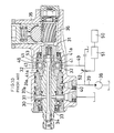
- the conventional power steering device comprises an output shaft 31 disposed within a housing 30 and having a tubular rear portion 31a extending axially of the shaft.
- the tubular portion 31a is formed with a plurality of holes 32 extending radially through its peripheral wall and arranged circumferentially thereof at a specified spacing.
- a hollow input shaft 33 inserted at its front portion in the tubular portion 31a of the output shaft 31 and coaxial with the output shaft 31.
- a torsion bar 34 is provided between the output shaft 31 and the input shaft 33 so as not to rotate relative to these shafts 31, 33 about the axis thereof.
- the rotary valve 37 is adapted to introduce pressure oil, which is forwarded thereto by a hydraulic pump 38 driven, for example, by the rotation of the engine, into the housing 30 via a conduit 39 and an inlet port 40 in the housing 30, to supply the oil selectively to one of the two ports of an unillustrated power cylinder and to control the amount of supply.
- the end of the plunger 41 closer to the input shaft 33 is integrally formed with a spherical protuberance 41a.
- Positioned in coincidence with the holes 32 is an annular groove 42 formed in the outer periphery of the output shaft 31 over the entire circumference thereof.
- a split ring 43 is fitted in the annular groove 42 for restraining the plungers 41 from moving radially outward.
- annular groove 44 is also formed in the inner periphery of the housing 30 over the entire circumference thereof and is opposed to the holes 32.
- annular grooves 45 are formed in the outer periphery of the output shaft 31 over the entire circumference thereof.
- An O-ring 46 and a seal ring 47 are fixedly fitted in each of these grooves 45.
- a branch pipe 49 branching from the conduit 39 and communicating with the pressure oil chamber 48 is provided with a hydraulic reaction control valve 52 controllable by a control unit 51 in accordance with the vehicle speed detected by a vehicle speed sensor 50.
- the periphery of the input shaft 33 is formed with a plurality of furrows 53 extending axially of the shaft, arranged at a specified spacing circumferentially thereof and opposed to the respective holes 32.
- Each of the furrows 53 is defined by a flat bottom surface 53a and opposite side surfaces 53b extending radially outward and inclined circumferentially outward.
- the pressure oil is introduced into the pressure oil chamber 48 in accordance with the vehicle speed, whereby the spherical protuberances 41a at the inner ends of the plungers 41 are pressed against the inner surfaces of the respective furrows 53 in the periphery of the input shaft 33 to increase the steering torque required for rotating the input shaft 33 about its axis.
- the reaction pressure to be applied to the plungers 41 increases with the steering pressure to be given to the power cylinder.
- FIG. 14 the solid lines represent the relationship between the steering torque and the steering pressure, i.e., steering characteristics, of the vehicle during running at a high speed.
- the steering torque only increases initially.
- the torsion bar 34 is twisted, increasing the steering pressure within one of the pressure oil chambers of the power cylinder.
- the reaction pressure to be given to the plungers 41 and the steering torque increase linearly (see FIG. 14, line A).
- each of the plungers 41 slightly slides in the hole 32 radially outward, with its protuberance 41a sliding on the bottom surface 53a of the furrow 53 rightward in FIG. 13.
- an unillustrated relief valve functions so as not to increase the steering pressure above the value.
- the output shaft 31 starts to rotate counterclockwise to decrease the steering torque (see FIG. 14, line C). This movement slightly slides down the protuberance 41a of the plunger 41 along the inclined side surface 53b of the furrow 53 to slightly slide the plunger 41 radially inward in the hole 32.
- the steering pressure decreases to a point Z, whereupon the reaction pressure also decreases with the decrease of the steering pressure, and the steering torque decreases linearly along with the steering pressure and the reaction pressure (see FIG. 14, line E).
- the plunger protuberance 41a slides on the furrow bottom surface 53a leftward in FIG. 13, and the plunger 41 slides radially inward within the hole 32. In this way, the front wheels are steered through a specified angle.
- each plunger 41 is made entirely of metal, a great frictional force occurs when the spherical protuberance 41a slides on the bottom surface 53a and the side surface 53b of the furrow 53 and also when the plunger 41 slides axially of the hole 32, with the result that the steering characteristics shown in FIG. 14 involve great hysteresis to give an impaired steering feeling.
- An object of the present invention is to solve the foregoing problems and to provide a vehicle speed responsive hydraulic power steering device which gives a more excellent steering feeling than the conventional device.
- Another object of the invention is to provide a vehicle speed responsive hydraulic power steering device wherein the plungers are adapted to strike on the input shaft with a diminished noise.
- plungers for use in the power steering device described above includes a plunger which is entirely made of a synthetic resin; a plunger comprising a synthetic resin body having a portion slidable in contact with the hole-defining inner peripheral surface of the output shaft, and an input shaft contacting metal ball fixed in the synthetic resin body; a plunger comprising a synthetic resin body having a portion slidable in contact with the hole-defining inner peripheral surface of the output shaft, and an input shaft contacting metal ball rollably attached to the synthetic resin body; and a plunger comprising a synthetic resin body, and an annular metal body secured to the periphery of the synthetic resin body and having an outer peripheral surface slidable in contact with the hole-defining inner peripheral surface of the output shaft, one end of the synthetic resin body closer to the input shaft being projected beyond one end of the annular metal body closer to the input shaft to provide a protuberance for contact with the input shaft.
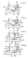
- the device includes plungers 1 each in the form of a solid cylinder and made entirely of a synthetic resin such as phenol resin.
- Each of the plungers 1 is integrally formed, at the end thereof toward the input shaft 33, with a spherical protuberance 1a, which serves as the portion to be pressed into contact with the bottom surface 53a and the side surface 53b defining the furrow 53 of the input shaft 33.
- the first embodiment has the same construction as the conventional power steering device already described.
- the synthetic resin used for the plunger 1 diminishes the sliding friction between the plunger protuberance 1a and the furrow bottom surface 53a and side surfaces 53b, and also diminishes the sliding friction between the peripheral surface of the plunger 1 and the inner peripheral surface defining the hole 32 formed in the output shaft 31. This reduces the hysteresis of the relationship between the steering torque and the steering pressure during steering, i.e., steering characteristics, as indicated in broken lines in FIG. 14, permitting the rotation of the output shaft 31 to follow the rotation of the steering wheel more effectively and giving an improved steering feeling.
- the plunger 1 is likely to move radially to strike against the input shaft 33 or against the split ring 43.
- the noise then produced is small because the striking portions of the plunger 1 are soft and also because the plunger has a reduced weight.
- FIG. 2 shows a second embodiment of the invention.
- the vehicle speed responsive hydraulic power steering device shown in FIG. 2 includes plungers 3 each comprising a synthetic resin body 4 having an outer peripheral surface slidable in contact with the inner peripheral surface of the output shaft 31 defining the hole 32, and a metal ball 5 fixed in the resin body 4 and adapted to contact the input shaft 33. Except for this feature, the second embodiment has the same construction as the conventional power steering device described.
- the metal ball 5 of the plunger 3 bears on the furrowed surface of the input shaft 33, so that the plunger portion is prevented from abrasion, hence a prolonged life.
- the second embodiment has the same advantages as the first.
- FIG. 3 shows a third embodiment of the invention.
- the vehicle speed responsive power steering device of FIG. 3 includes plungers 7 each comprising a synthetic resin body 8 having an outer peripheral surface slidable in contact with the inner peripheral surface of the output shaft 31 defining the hole 32, and a metal ball 9 rollably fitted in a blind bore 8a formed in the end of the resin body 8 closer to the input shaft 33 to contact the input shaft 33.
- the third embodiment has the same construction as the conventional power steering device described.
- the metal ball 9 is rollable relative to the resin body 8, so that when brought into contact with the inner surface of the input shaft 33 defining the furrow 53, the metal ball 9 rolls along with diminished friction between the ball 9 and the furrowed surface of the input shaft 33.
- the third embodiment has the same advantages as the second embodiment described.
- FIG. 4 shows a fourth embodiment of the invention.
- the vehicle speed responsive hydraulic power steering device of FIG. 4 includes plungers 11 each comprising a synthetic resin body 12 in the form of a solid cylinder, and an annular metal body 13 secured to the periphery of the resin body 12 and having an outer peripheral surface slidable in contact with the inner peripheral surface of the output shaft 31 defining the hole 32.
- the end of the resin body 12 closer to the input shaft 33 is projected beyond the corresponding end of the metal body 13 to provide a spherical protuberance 12a.
- the protuberance 12a serves as the portion to be brought into contact with the inner surface of the input shaft 33 defining the furrow 53.
- the fourth embodiment has the same construction as the conventional power steering device described.
- the other end of the resin body 16 is also projected beyond the metal body 17, and the projected end is provided around its periphery with a cover portion 16b covering the other end of the metal body 17.
- the other end of the resin body 16 opposite to its protuberance 16a is formed with a cavity 16c for reducing the weight of the resin body.
- the fifth embodiment has the same construction as the conventional power steering device described.
- the cover portion 16b serves to diminish the striking noise to be produced when the plunger 15 moves away from the input shaft 33 into contact with the ring 43. Except for this advantage, the present embodiment has the same advantages as the fourth embodiment.
- the plungers of the fourth and fifth embodiments are prepared, for example, by molding a synthetic resin inside the annular metal body as joined with the metal body by injection molding, and finishing the molding as by polishing.
- FIG. 6 shows a sixth embodiment of the invention.
- the vehicle speed responsive hydraulic power steering device of FIG. 6 includes plungers 19 each comprising a solid cylindrical body 20 of a synthetic resin such as fiber-reinforced nylon 66 filled with glass fiber, and an annular metal body 21 secured to the periphery of the resin body 20 and made, for example, of JIS SUJ2 as hardened or a sintered alloy.
- the outer peripheral surface of the annular metal body 21 is slidable in contact with the inner peripheral surface of the output shaft 31 defining the hole 32.
- One end of the synthetic resin body 20 closer to the input shaft 33 is projected in its entirety beyond the annular metal body 21 to provide a spherical protuberance 20a, which serves as the portion to be contacted with the bottom surface 53a and the side surfaces 53b defining the furrow 53 in the input shaft 33.
- the other end of the resin body 20 is caved in from the corresponding end of the annular metal body 21 to form a recess 20b larger than the spherical protuberance 20a and having such a size that the protuberance 20a can be fitted in the recess.
- the recessed end of the resin body 20 has a concave surface.
- a cavity 20c for reducing the weight of the plunger extends from the central portion of the concave surface toward the protuberance 20a.
- An annular projection 21a is formed on the inner periphery of the metal body 21 for preventing the resin body 20 from slipping off. Except for the above feature, the sixth embodiment has the same construction as the conventional power steering device described.
- the plunger 19 is prepared, for example, by molding the synthetic resin body 20 inside the annular metal body 21 as joined thereto. As shown in FIG. 7, a plurality of such plungers 19 are fitted together by placing the protuberance 20a of the resin body 20 of each plunger 19 into the recess 20b of the resin body 20 of another plunger 19, and the outer peripheral surfaces of the metal bodies 21 of all the plungers 19 are polished at the same for finishing, for example, by a centerless polishing device.
- the plungers 19 can therefore be prepared easily. Except for the above advantage, the present embodiment has the same advantages as the fourth embodiment.
- FIG. 8 shows a seventh embodiment of the invention.
- the vehicle speed responsive hydraulic power steering device of FIG. 8 includes plungers 23 each comprising a solid cylindrical body 24 of a synthetic resin such as fiber-reinforced nylon 66 filled with glass fiber, and an annular metal body 25 fixedly fitted around the resin body 24 and made, for example, of JIS SUJ2 as hardened or a sintered alloy.
- One end of the synthetic resin body 24 closer to the input shaft 33 is projected beyond the corresponding end of the metal body 25 to provide a spherical protuberance 24a, which serves as the portion to be contacted with the bottom surface 53a and the side surfaces 53b defining the furrow of the input shaft 33.
- the peripheral edge of the spherical protuberance 24a extends radially outward to provide a flange 24b.
- the other end of the resin body 24 is at a lower level than the metal body 25.
- An annular projection 25a having a predetermined width from the base end of the protuberance 24a is formed on the inner periphery of the metal body 25.
- the inner periphery of the metal body 25 above the annular projection 25a toward the other end provides a relief 25b for the resin body 24 when the body 24 thermally expands.
- the plunger 23 is prepared by forming the annular metal body 25, making the resin body 24 by injection molding separately from the metal body, and forcing the other end, opposite to the protuberance 24a, of the resin body 24 into the metal body 25 to bring the flange 24b into engagement with the metal body 25.
- the outside diameter of the plunger 23 can be altered merely by varying the wall thickness of the metal body 25 without varying the size of the resin body 24.
- synthetic resin molding dies are expensive, only one kind of such dies therefore needs to be prepared, hence a cost reduction.
- the plunger is axially slidably fitted in a hole formed in a tubular portion of the output shaft and extending radially thereof
- the present invention is not limited to such arrangement but is also applicable to a device which comprises, as disclosed in Unexamined Japanese Utility Model Publication SHO 63-75471, an input shaft integrally formed with radially extending projections, an output shaft having bores extending perpendicular to its axis and positioned on the axially opposed sides of the projections, and plungers slidably fitted in the respective bores to hold the projections between the opposed plunger ends to deliver a hydraulic reaction.
Landscapes
- Engineering & Computer Science (AREA)
- Chemical & Material Sciences (AREA)
- Combustion & Propulsion (AREA)
- Transportation (AREA)
- Mechanical Engineering (AREA)
- Steering Control In Accordance With Driving Conditions (AREA)
- Power Steering Mechanism (AREA)
Applications Claiming Priority (6)
| Application Number | Priority Date | Filing Date | Title |
|---|---|---|---|
| JP1990040450U JPH03130769U (fr) | 1990-04-16 | 1990-04-16 | |
| JP40450/90 | 1990-04-16 | ||
| JP117582/90 | 1990-11-07 | ||
| JP1990117582U JPH0474179U (fr) | 1990-11-07 | 1990-11-07 | |
| JP117788/90 | 1990-11-09 | ||
| JP1990117788U JP2542486Y2 (ja) | 1990-11-09 | 1990-11-09 | 車速応動型油圧式パワーステアリング装置 |
Publications (2)
| Publication Number | Publication Date |
|---|---|
| EP0453919A1 true EP0453919A1 (fr) | 1991-10-30 |
| EP0453919B1 EP0453919B1 (fr) | 1995-08-23 |
Family
ID=27290481
Family Applications (1)
| Application Number | Title | Priority Date | Filing Date |
|---|---|---|---|
| EP91105988A Expired - Lifetime EP0453919B1 (fr) | 1990-04-16 | 1991-04-15 | Système de direction assistée hydraulique réagissant à la vitesse du véhicule |
Country Status (5)
| Country | Link |
|---|---|
| US (1) | US5190119A (fr) |
| EP (1) | EP0453919B1 (fr) |
| KR (1) | KR0157632B1 (fr) |
| DE (1) | DE69112256T2 (fr) |
| FR (1) | FR2660904B1 (fr) |
Cited By (3)
| Publication number | Priority date | Publication date | Assignee | Title |
|---|---|---|---|---|
| AU653442B2 (en) * | 1991-10-23 | 1994-09-29 | Mitsubishi Jidosha Kogyo Kabushiki Kaisha | Power steering apparatus for vehicle |
| DE4315895B4 (de) * | 1993-05-12 | 2008-04-03 | Zf Friedrichshafen Ag | Lenkkraftverstärker |
| US8960358B2 (en) | 2013-06-27 | 2015-02-24 | Robert Bosch Gmbh | Speed-based hydraulic pump control system and method for noise reduction in hybrid vehicles |
Families Citing this family (13)
| Publication number | Priority date | Publication date | Assignee | Title |
|---|---|---|---|---|
| DE4232813A1 (de) * | 1992-09-30 | 1994-03-31 | Zahnradfabrik Friedrichshafen | Zentriereinrichtung, insbesondere für Lenkventile |
| US5465805A (en) * | 1993-09-03 | 1995-11-14 | Trw Inc. | Power steering system |
| US5452642A (en) * | 1994-02-02 | 1995-09-26 | Trw Inc. | Power steering system with speed responsive force transmitting control |
| KR0135019B1 (ko) * | 1994-12-12 | 1998-04-23 | 정몽원 | 자동차용 조향핸들의 파워스티어링장치 |
| US5697400A (en) * | 1995-06-29 | 1997-12-16 | Trw Fahrwerksysteme Gmbh & Co. Kg | Steering valve |
| KR970036864U (ko) * | 1995-12-27 | 1997-07-26 | 자동차용 유압제어 밸브의 구조 | |
| US5842538A (en) * | 1996-02-28 | 1998-12-01 | Trw Inc. | Power steering control valve |
| JP3146981B2 (ja) * | 1996-07-09 | 2001-03-19 | トヨタ自動車株式会社 | 動力舵取装置 |
| EP1026067B1 (fr) * | 1999-02-04 | 2003-12-17 | Ntn Corporation | Dispositif de direction assistée éléctrique |
| US7143683B2 (en) * | 2003-09-24 | 2006-12-05 | Koyo Seiko Co., Ltd. | Hydraulic power steering apparatus |
| US7819217B2 (en) * | 2005-12-23 | 2010-10-26 | Hitachi, Ltd. | Power steering apparatus, method of controlling the same and method of assembling the same |
| DE102007028726B4 (de) * | 2006-08-03 | 2010-12-16 | Hitachi, Ltd. | Servolenkungsvorrichtung, dessen Steuerungs-/Regelungsverfahren und Montageverfahren |
| JP2009006948A (ja) * | 2007-06-29 | 2009-01-15 | Hitachi Ltd | パワーステアリング装置 |
Citations (6)
| Publication number | Priority date | Publication date | Assignee | Title |
|---|---|---|---|---|
| DE3516219A1 (de) * | 1984-05-09 | 1985-11-14 | Koyo Jidoki K.K., Kashihara, Nara | Servolenkvorrichtung eines fahrzeugs |
| DE3625600A1 (de) * | 1985-07-31 | 1987-02-12 | Mitsubishi Motors Corp | Servolenkanlage |
| DE3720150A1 (de) * | 1986-06-19 | 1987-12-23 | Jidosha Kiki Co | Hydraulischer reaktionskraftverstaerker fuer eine servolenkung |
| US4796715A (en) * | 1985-03-01 | 1989-01-10 | Koyo Jidoki Kabushiki Kaisha | Hydraulic pressure reaction device in a power steering device |
| EP0299617A2 (fr) * | 1987-07-16 | 1989-01-18 | General Motors Corporation | Boîtier de direction avec détente sensible à la vitesse |
| EP0302267A2 (fr) * | 1987-07-28 | 1989-02-08 | Trw Inc. | Système de direction assistée |
Family Cites Families (4)
| Publication number | Priority date | Publication date | Assignee | Title |
|---|---|---|---|---|
| JPH0649460B2 (ja) * | 1985-03-01 | 1994-06-29 | 光洋精工株式会社 | 油圧反力式パワーステアリング装置 |
| JPH0649461B2 (ja) * | 1985-03-18 | 1994-06-29 | 光洋精工株式会社 | 油圧反力式パワーステアリング装置 |
| JPH082757B2 (ja) * | 1988-11-15 | 1996-01-17 | 光洋精工株式会社 | 動力舵取装置 |
| US5070957A (en) * | 1990-11-20 | 1991-12-10 | General Motors Corporation | Variable effort automotive power steering gear |
-
1991
- 1991-03-25 US US07/674,115 patent/US5190119A/en not_active Expired - Lifetime
- 1991-04-12 KR KR1019910005835A patent/KR0157632B1/ko not_active Expired - Fee Related
- 1991-04-15 DE DE69112256T patent/DE69112256T2/de not_active Expired - Fee Related
- 1991-04-15 FR FR9104580A patent/FR2660904B1/fr not_active Expired - Fee Related
- 1991-04-15 EP EP91105988A patent/EP0453919B1/fr not_active Expired - Lifetime
Patent Citations (6)
| Publication number | Priority date | Publication date | Assignee | Title |
|---|---|---|---|---|
| DE3516219A1 (de) * | 1984-05-09 | 1985-11-14 | Koyo Jidoki K.K., Kashihara, Nara | Servolenkvorrichtung eines fahrzeugs |
| US4796715A (en) * | 1985-03-01 | 1989-01-10 | Koyo Jidoki Kabushiki Kaisha | Hydraulic pressure reaction device in a power steering device |
| DE3625600A1 (de) * | 1985-07-31 | 1987-02-12 | Mitsubishi Motors Corp | Servolenkanlage |
| DE3720150A1 (de) * | 1986-06-19 | 1987-12-23 | Jidosha Kiki Co | Hydraulischer reaktionskraftverstaerker fuer eine servolenkung |
| EP0299617A2 (fr) * | 1987-07-16 | 1989-01-18 | General Motors Corporation | Boîtier de direction avec détente sensible à la vitesse |
| EP0302267A2 (fr) * | 1987-07-28 | 1989-02-08 | Trw Inc. | Système de direction assistée |
Cited By (3)
| Publication number | Priority date | Publication date | Assignee | Title |
|---|---|---|---|---|
| AU653442B2 (en) * | 1991-10-23 | 1994-09-29 | Mitsubishi Jidosha Kogyo Kabushiki Kaisha | Power steering apparatus for vehicle |
| DE4315895B4 (de) * | 1993-05-12 | 2008-04-03 | Zf Friedrichshafen Ag | Lenkkraftverstärker |
| US8960358B2 (en) | 2013-06-27 | 2015-02-24 | Robert Bosch Gmbh | Speed-based hydraulic pump control system and method for noise reduction in hybrid vehicles |
Also Published As
| Publication number | Publication date |
|---|---|
| US5190119A (en) | 1993-03-02 |
| FR2660904A1 (fr) | 1991-10-18 |
| DE69112256T2 (de) | 1996-04-04 |
| EP0453919B1 (fr) | 1995-08-23 |
| KR910018256A (ko) | 1991-11-30 |
| DE69112256D1 (de) | 1995-09-28 |
| KR0157632B1 (ko) | 1998-10-15 |
| FR2660904B1 (fr) | 1994-01-21 |
Similar Documents
| Publication | Publication Date | Title |
|---|---|---|
| EP0453919B1 (fr) | Système de direction assistée hydraulique réagissant à la vitesse du véhicule | |
| US6918457B2 (en) | Electric power steering system | |
| US4809806A (en) | Steering gear with hybrid housing | |
| US4759420A (en) | Steering gear with speed sensitive detent switch | |
| US4648307A (en) | Unloading valve for power steering piston with integral gear | |
| JP3628330B2 (ja) | 自動車のパワーステアリング装置のおける回転スライド弁 | |
| HU176182B (en) | Control device of pressure medium for power assisted steering units, in particular to motor vehicles | |
| US4458580A (en) | Power steering apparatus | |
| US6363833B1 (en) | Piston for hydraulic power assist rack and pinion steering system | |
| JP3543043B2 (ja) | 油圧パワーステアリング装置 | |
| JP2542486Y2 (ja) | 車速応動型油圧式パワーステアリング装置 | |
| EP1108497A2 (fr) | Unité de broche | |
| JP2001520959A (ja) | 自動車の動力舵取り装置のロータリ・シフト弁 | |
| EP0467333B1 (fr) | Système de direction assistée hydraulique | |
| JPS61160362A (ja) | パワ−ステアリング装置 | |
| JPH0258018B2 (fr) | ||
| JP2914455B2 (ja) | 動力舵取装置 | |
| JPH04123879U (ja) | 油圧反力式パワーステアリング装置 | |
| JPH0151391B2 (fr) | ||
| JP2974029B2 (ja) | パワーステアリング装置におけるピストンキャップの装着方法 | |
| JPH05262247A (ja) | ボールスクリュー型油圧パワーステアリング装置 | |
| JPH0547740Y2 (fr) | ||
| JPS6137570Y2 (fr) | ||
| KR950013090B1 (ko) | 자동차용 동력조향장치 | |
| GB1576051A (en) | Hydraulic servo steering unit for a motor vehicle |
Legal Events
| Date | Code | Title | Description |
|---|---|---|---|
| PUAI | Public reference made under article 153(3) epc to a published international application that has entered the european phase |
Free format text: ORIGINAL CODE: 0009012 |
|
| AK | Designated contracting states |
Kind code of ref document: A1 Designated state(s): DE ES GB IT SE |
|
| 17P | Request for examination filed |
Effective date: 19911211 |
|
| 17Q | First examination report despatched |
Effective date: 19940426 |
|
| GRAA | (expected) grant |
Free format text: ORIGINAL CODE: 0009210 |
|
| AK | Designated contracting states |
Kind code of ref document: B1 Designated state(s): DE ES GB IT SE |
|
| PG25 | Lapsed in a contracting state [announced via postgrant information from national office to epo] |
Ref country code: IT Free format text: LAPSE BECAUSE OF FAILURE TO SUBMIT A TRANSLATION OF THE DESCRIPTION OR TO PAY THE FEE WITHIN THE PRE;WARNING: LAPSES OF ITALIAN PATENTS WITH EFFECTIVE DATE BEFORE 2007 MAY HAVE OCCURRED AT ANY TIME BEFORE 2007. THE CORRECT EFFECTIVE DATE MAY BE DIFFERENT FROM THE ONE RECORDED.SCRIBED TIME-LIMIT Effective date: 19950823 Ref country code: ES Free format text: THE PATENT HAS BEEN ANNULLED BY A DECISION OF A NATIONAL AUTHORITY Effective date: 19950823 |
|
| REF | Corresponds to: |
Ref document number: 69112256 Country of ref document: DE Date of ref document: 19950928 |
|
| PG25 | Lapsed in a contracting state [announced via postgrant information from national office to epo] |
Ref country code: SE Effective date: 19951123 |
|
| PLBE | No opposition filed within time limit |
Free format text: ORIGINAL CODE: 0009261 |
|
| STAA | Information on the status of an ep patent application or granted ep patent |
Free format text: STATUS: NO OPPOSITION FILED WITHIN TIME LIMIT |
|
| 26N | No opposition filed | ||
| REG | Reference to a national code |
Ref country code: GB Ref legal event code: IF02 |
|
| PGFP | Annual fee paid to national office [announced via postgrant information from national office to epo] |
Ref country code: DE Payment date: 20080424 Year of fee payment: 18 |
|
| PGFP | Annual fee paid to national office [announced via postgrant information from national office to epo] |
Ref country code: GB Payment date: 20080416 Year of fee payment: 18 |
|
| GBPC | Gb: european patent ceased through non-payment of renewal fee |
Effective date: 20090415 |
|
| PG25 | Lapsed in a contracting state [announced via postgrant information from national office to epo] |
Ref country code: DE Free format text: LAPSE BECAUSE OF NON-PAYMENT OF DUE FEES Effective date: 20091103 |
|
| PG25 | Lapsed in a contracting state [announced via postgrant information from national office to epo] |
Ref country code: GB Free format text: LAPSE BECAUSE OF NON-PAYMENT OF DUE FEES Effective date: 20090415 |