EP0459429B1 - Kraftstoffeinspritzventil - Google Patents
Kraftstoffeinspritzventil Download PDFInfo
- Publication number
- EP0459429B1 EP0459429B1 EP91108747A EP91108747A EP0459429B1 EP 0459429 B1 EP0459429 B1 EP 0459429B1 EP 91108747 A EP91108747 A EP 91108747A EP 91108747 A EP91108747 A EP 91108747A EP 0459429 B1 EP0459429 B1 EP 0459429B1
- Authority
- EP
- European Patent Office
- Prior art keywords
- fuel
- pressure
- valve
- chamber
- passageway
- Prior art date
- Legal status (The legal status is an assumption and is not a legal conclusion. Google has not performed a legal analysis and makes no representation as to the accuracy of the status listed.)
- Expired - Lifetime
Links
- 239000000446 fuel Substances 0.000 title claims description 253
- 238000002347 injection Methods 0.000 claims description 42
- 239000007924 injection Substances 0.000 claims description 42
- 230000006835 compression Effects 0.000 claims description 12
- 238000007906 compression Methods 0.000 claims description 12
- 230000002093 peripheral effect Effects 0.000 claims description 11
- 230000007613 environmental effect Effects 0.000 claims description 7
- 238000011144 upstream manufacturing Methods 0.000 claims 1
- 238000002485 combustion reaction Methods 0.000 description 16
- 230000001133 acceleration Effects 0.000 description 5
- 230000000881 depressing effect Effects 0.000 description 5
- 238000010586 diagram Methods 0.000 description 3
- 230000002238 attenuated effect Effects 0.000 description 2
- 230000000694 effects Effects 0.000 description 1
- 239000002828 fuel tank Substances 0.000 description 1
- 230000004044 response Effects 0.000 description 1
- 230000004043 responsiveness Effects 0.000 description 1
Images


Classifications
-
- F—MECHANICAL ENGINEERING; LIGHTING; HEATING; WEAPONS; BLASTING
- F02—COMBUSTION ENGINES; HOT-GAS OR COMBUSTION-PRODUCT ENGINE PLANTS
- F02M—SUPPLYING COMBUSTION ENGINES IN GENERAL WITH COMBUSTIBLE MIXTURES OR CONSTITUENTS THEREOF
- F02M63/00—Other fuel-injection apparatus having pertinent characteristics not provided for in groups F02M39/00 - F02M57/00 or F02M67/00; Details, component parts, or accessories of fuel-injection apparatus, not provided for in, or of interest apart from, the apparatus of groups F02M39/00 - F02M61/00 or F02M67/00; Combination of fuel pump with other devices, e.g. lubricating oil pump
- F02M63/02—Fuel-injection apparatus having several injectors fed by a common pumping element, or having several pumping elements feeding a common injector; Fuel-injection apparatus having provisions for cutting-out pumps, pumping elements, or injectors; Fuel-injection apparatus having provisions for variably interconnecting pumping elements and injectors alternatively
- F02M63/0225—Fuel-injection apparatus having a common rail feeding several injectors ; Means for varying pressure in common rails; Pumps feeding common rails
-
- F—MECHANICAL ENGINEERING; LIGHTING; HEATING; WEAPONS; BLASTING
- F02—COMBUSTION ENGINES; HOT-GAS OR COMBUSTION-PRODUCT ENGINE PLANTS
- F02M—SUPPLYING COMBUSTION ENGINES IN GENERAL WITH COMBUSTIBLE MIXTURES OR CONSTITUENTS THEREOF
- F02M45/00—Fuel-injection apparatus characterised by having a cyclic delivery of specific time/pressure or time/quantity relationship
-
- F—MECHANICAL ENGINEERING; LIGHTING; HEATING; WEAPONS; BLASTING
- F02—COMBUSTION ENGINES; HOT-GAS OR COMBUSTION-PRODUCT ENGINE PLANTS
- F02M—SUPPLYING COMBUSTION ENGINES IN GENERAL WITH COMBUSTIBLE MIXTURES OR CONSTITUENTS THEREOF
- F02M47/00—Fuel-injection apparatus operated cyclically with fuel-injection valves actuated by fluid pressure
- F02M47/02—Fuel-injection apparatus operated cyclically with fuel-injection valves actuated by fluid pressure of accumulator-injector type, i.e. having fuel pressure of accumulator tending to open, and fuel pressure in other chamber tending to close, injection valves and having means for periodically releasing that closing pressure
- F02M47/027—Electrically actuated valves draining the chamber to release the closing pressure
-
- F—MECHANICAL ENGINEERING; LIGHTING; HEATING; WEAPONS; BLASTING
- F02—COMBUSTION ENGINES; HOT-GAS OR COMBUSTION-PRODUCT ENGINE PLANTS
- F02M—SUPPLYING COMBUSTION ENGINES IN GENERAL WITH COMBUSTIBLE MIXTURES OR CONSTITUENTS THEREOF
- F02M55/00—Fuel-injection apparatus characterised by their fuel conduits or their venting means; Arrangements of conduits between fuel tank and pump F02M37/00
- F02M55/02—Conduits between injection pumps and injectors, e.g. conduits between pump and common-rail or conduits between common-rail and injectors
- F02M55/025—Common rails
-
- F—MECHANICAL ENGINEERING; LIGHTING; HEATING; WEAPONS; BLASTING
- F02—COMBUSTION ENGINES; HOT-GAS OR COMBUSTION-PRODUCT ENGINE PLANTS
- F02M—SUPPLYING COMBUSTION ENGINES IN GENERAL WITH COMBUSTIBLE MIXTURES OR CONSTITUENTS THEREOF
- F02M63/00—Other fuel-injection apparatus having pertinent characteristics not provided for in groups F02M39/00 - F02M57/00 or F02M67/00; Details, component parts, or accessories of fuel-injection apparatus, not provided for in, or of interest apart from, the apparatus of groups F02M39/00 - F02M61/00 or F02M67/00; Combination of fuel pump with other devices, e.g. lubricating oil pump
- F02M63/0012—Valves
- F02M63/0031—Valves characterized by the type of valves, e.g. special valve member details, valve seat details, valve housing details
- F02M63/0045—Three-way valves
-
- F—MECHANICAL ENGINEERING; LIGHTING; HEATING; WEAPONS; BLASTING
- F02—COMBUSTION ENGINES; HOT-GAS OR COMBUSTION-PRODUCT ENGINE PLANTS
- F02M—SUPPLYING COMBUSTION ENGINES IN GENERAL WITH COMBUSTIBLE MIXTURES OR CONSTITUENTS THEREOF
- F02M63/00—Other fuel-injection apparatus having pertinent characteristics not provided for in groups F02M39/00 - F02M57/00 or F02M67/00; Details, component parts, or accessories of fuel-injection apparatus, not provided for in, or of interest apart from, the apparatus of groups F02M39/00 - F02M61/00 or F02M67/00; Combination of fuel pump with other devices, e.g. lubricating oil pump
- F02M63/0012—Valves
- F02M63/007—Details not provided for in, or of interest apart from, the apparatus of the groups F02M63/0014 - F02M63/0059
- F02M63/0073—Pressure balanced valves
-
- F—MECHANICAL ENGINEERING; LIGHTING; HEATING; WEAPONS; BLASTING
- F02—COMBUSTION ENGINES; HOT-GAS OR COMBUSTION-PRODUCT ENGINE PLANTS
- F02M—SUPPLYING COMBUSTION ENGINES IN GENERAL WITH COMBUSTIBLE MIXTURES OR CONSTITUENTS THEREOF
- F02M63/00—Other fuel-injection apparatus having pertinent characteristics not provided for in groups F02M39/00 - F02M57/00 or F02M67/00; Details, component parts, or accessories of fuel-injection apparatus, not provided for in, or of interest apart from, the apparatus of groups F02M39/00 - F02M61/00 or F02M67/00; Combination of fuel pump with other devices, e.g. lubricating oil pump
- F02M63/0012—Valves
- F02M63/007—Details not provided for in, or of interest apart from, the apparatus of the groups F02M63/0014 - F02M63/0059
- F02M63/0078—Valve member details, e.g. special shape, hollow or fuel passages in the valve member
- F02M63/008—Hollow valve members, e.g. members internally guided
-
- F—MECHANICAL ENGINEERING; LIGHTING; HEATING; WEAPONS; BLASTING
- F02—COMBUSTION ENGINES; HOT-GAS OR COMBUSTION-PRODUCT ENGINE PLANTS
- F02D—CONTROLLING COMBUSTION ENGINES
- F02D2250/00—Engine control related to specific problems or objectives
- F02D2250/31—Control of the fuel pressure
-
- F—MECHANICAL ENGINEERING; LIGHTING; HEATING; WEAPONS; BLASTING
- F02—COMBUSTION ENGINES; HOT-GAS OR COMBUSTION-PRODUCT ENGINE PLANTS
- F02D—CONTROLLING COMBUSTION ENGINES
- F02D41/00—Electrical control of supply of combustible mixture or its constituents
- F02D41/30—Controlling fuel injection
- F02D41/38—Controlling fuel injection of the high pressure type
- F02D41/3809—Common rail control systems
-
- F—MECHANICAL ENGINEERING; LIGHTING; HEATING; WEAPONS; BLASTING
- F02—COMBUSTION ENGINES; HOT-GAS OR COMBUSTION-PRODUCT ENGINE PLANTS
- F02M—SUPPLYING COMBUSTION ENGINES IN GENERAL WITH COMBUSTIBLE MIXTURES OR CONSTITUENTS THEREOF
- F02M2200/00—Details of fuel-injection apparatus, not otherwise provided for
- F02M2200/28—Details of throttles in fuel-injection apparatus
Definitions
- the present invention relates to a fuel injector.
- a fuel injector which is provided with a needle opened by a fuel pressure in a high pressure passageway.
- This fuel injector comprises a pressure chamber with a slidable piston connected to said needle, wherein said needle is closed when a fuel pressure in said pressure chamber is raised and is opened when said fuel pressure is lowered.
- Said fuel injector further comprises a check valve for permitting fuel to flow only from the pressure chamber via a restricted opening.
- a further fuel injector which is opened by moving a needle with the aid of a fuel pressure in a high pressure passageway, wherein a pressure chamber defined by the rear surface of the needle and connected to the high pressure passageway is formed in the fuel injector and a restricted opening and a check valve are arranged such that fuel easily flows in the region between the pressure chamber and the high pressure passageway but the flow out of fuel from the pressure chamber is restricted to thus raise the fuel injection pressure and maintain a good fuel injection completion is known (see Japanese Unexamined Utility Model Publication No. 1-114979).
- a fuel injection rate of fuel from the fuel injector is gradually increased. Namely, the fuel injection rate is gradually increased with an elapse of time from the time at which the fuel injection is started.
- the fuel injection rate is quickly raised because a large quantity of fuel must be supplied to each combustion chamber a short time. Namely, preferably the raising of the fuel injection rate is varied in accordance with the current running state of the engine.
- the present invention has been created in consideration of the above problems.
- an object of the present invention is to provide a fuel injector by which a pattern representing a fuel injection rate can be changed to a desired fuel injection rate pattern corresponding to the current running state of an engine.
- a fuel injector including a needle and a pressure chamber defined by the rear surface of the needle, the needle being closed when a fuel pressure in the pressure chamber is high and being open when the fuel pressure in the pressure chamber is low
- the fuel injector comprising: a pressure control chamber formed in the region adjacent to the pressure chamber; a restricted opening arranged between the pressure chamber and the pressure control chamber; a check valve for permitting fuel to flow only in the direction from the pressure control chamber toward the pressure chamber; an opening and closing valve opening when the fuel pressure in the pressure control chamber becomes lower than the fuel pressure in the pressure chamber by a predetermined first pressure, the restricted opening, the check valve and the opening and closing valve being arranged in parallel to each other; and fuel pressure controlling means for controlling a fuel pressure in the pressure control chamber, the fuel pressure controlling means raising the fuel pressure in the pressure control chamber to introduce fuel in the pressure control chamber into the pressure chamber via the check valve, the fuel pressure controlling means lowering the fuel pressure in the pressure control chamber to discharge fuel in the pressure chamber into the pressure control chamber via
- a nozzle main body 1 is formed with a single nozzle 2 or a plurality of nozzles 2 and a nozzle seat 3; a needle 4 is slidably received in the nozzle main body 1 to slidably move in the axial direction, and a valve portion 5 and a pressure receiving portion 6 are formed on the needle 4; and a fuel pressure in a fuel chamber 7 formed between the needle body 1 and the needle 4 is exerted on the pressure receiving portion 6.
- the fuel chamber 7 is communicated with a common rail 41 via a fuel passageway 40.
- a rod 10 is connected to the rear surface of the needle 4 and a piston 12 is connected to the upper end of the rod 10, and the piston 12 is slidably received in a cylinder 13 which is formed in the nozzle main body 1.
- a spring holding portion 11 is formed on the rod 10 such that a compression spring 14 is mounted on the spring holding portion 11 so as to allow the needle 4 to be normally biased in the valve-closing direction.
- a pressure chamber 17 is formed on the rear surface side of the piston 12 and a pressure control chamber 18 is arranged in the region adjacent to the pressure chamber 17. According to the embodiment of the present invention shown in Fig. 1, the pressure chamber 17 is communicated with the pressure control chamber 18 at the central part of the bottom wall of the pressure control chamber 18.
- a valve disc 21 is received in the pressure control chamber 18 so that it is normally brought into close contact with the bottom wall surface of the pressure control chamber 18 by the resilient force of a compression spring 20. When the valve disc 21 is located on the bottom wall surface of the pressure control chamber 18 in the above-described manner, an aperture of the pressure chamber 17 is closed with the valve disc 21.
- a through hole 26 is formed in the valve disc 21, and an orifice valve disc 23 is disposed in the pressure chamber 17 such that the orifice valve disc 23 is biased toward the valve disc 21 by a compression spring 22.
- the through hole 26 is normally closed with the orifice valve disc 23.
- a restricted opening 25 is formed at the central part of the orifice valve disc 23 in alignment with the through hole 26.
- the through hole 26, the orifice valve disc 23 and the compression spring 22 constitute a check valve 28 which permits fuel to flow only from the pressure control chamber 18 toward the pressure chamber 17.
- the valve disc 21 and the compression spring 20 constitute an opening and closing valve 29 which is opened when the fuel pressure in the pressure control chamber 18 becomes lower than the fuel pressure in the pressure chamber 17 by a predetermined first pressure.
- the pressure required for opening the opening and closing valve 29 is determined depending on the resilient force of the compression spring 20, for example, the pressure is set to about 550 kg/cm2.
- the restricted opening 25, the check valve 28 and the opening and closing valve 29 are arranged in series to each other from the viewpoint of structure, but are practically arranged in parallel to each other from the viewpoint of function. Therefore, a parallel arrangement of the aforementioned components from the viewpoint of function is referred to as "arranged in parallel to each other" throughout the specification.
- a fuel pressure in the pressure control chamber 18 is controlled by a fuel pressure control unit 35, which comprises a fuel injection pump 45 and a solenoid valve 30.
- the solenoid valve 30 is composed of an exciting coil 62 disposed in a casing 61, a stator 63 and a movable valve disc 64 slidably disposed in the stator 63 to move slidably relative to the stator 63. While the coil 62 is turned off, the movable valve disc 64 is held at the position as shown in Fig. 1, and at this time, the movable valve disc 64 is brought into close contact with a valve seat 68, to thereby isolate an atmosphere communication passageway 69 leading to an environmental atmosphere from the pressure control chamber 18.
- the pressure control chamber 18 is communicated with a fuel passageway 40 via a passageway 65 in the casing 61, a passageway 66 in the movable valve disc 64, and a communication hole 67 formed on the peripheral wall of the movable valve disc 64.
- the movable valve disc 64 is displaced in the upward direction as seen in Fig. 1 by the effect of a magnetic attractive force.
- a valve portion 70 of the movable valve disc 64 is brought into close contact with the stator 63, whereby the pressure control chamber 18 is isolated from the fuel passageway 40.
- the movable valve disc 64 is released from the valve seat 68, and thus the pressure control chamber 18 is exposed to an environmental atmosphere via the atmosphere communication passageway 69.
- the common rail 41 leads to a cylinder 46 in the fuel injection pump 45 via a discharge passageway 43, and the cylinder 46 leads to a fuel tank 50 via a fuel supply passageway 49 and a fuel pump 53.
- a piston 47 is slidably received in the cylinder 46 so that a fuel is pumped to the common rail 41 as the piston 47 reciprocably moves in the cylinder 46.
- the fuel pressure control unit 35 is provided with a fuel return passageway 51 which connects the discharge passageway 43 to the fuel supply passageway 49.
- a discharged fuel quantity control valve 52 is disposed in the fuel return passageway 51.
- the discharged fuel quantity control valve 52 When the discharged fuel quantity control valve 52 is open, a fuel discharged from the cylinder 46 is returned to the fuel supply passageway 49 via the fuel return passageway 51, and when the discharged fuel quantity control valve 52 is closed, a fuel discharged from the cylinder 46 is squeezed in the common rail 41, and thus a fuel pressure in the common rail 41 is immediately raised. Therefore, the fuel pressure P in the common rail 41 can be varied with a good responsiveness by properly controlling the time for which the discharged fuel quantity control valve 52 is kept open during a compression stroke of the piston 47.
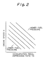
- the fuel pressure P in the common rail 41 is controlled in accordance with an acceleration pedal depressing rate TA and an engine speed N.
- Figure 2 shows a target fuel pressure P0 of the fuel pressure P in the common rail 41, wherein group of curves represents a curve along which the target fuel pressure P0 is kept constant, respectively.
- the larger the acceleration pedal depressing rate TA the higher the target fuel pressure P0.
- the larger the engine speed N the higher the target fuel pressure P0.
- an upper limit value of the target fuel pressure P0 is set to, e.g., about 1300 kg/cm2 and a lower limit value of the same is set to, e.g., about 170 kg/cm2.
- a control circuit 60 calculates the target fuel pressure P0 based on the acceleration pedal depressing rate TA detected by an acceleration pedal depressing rate sensor 57 and the engine speed N detected by an engine speed sensor 58, with reference to the map shown in Fig. 2. Further, the control circuit 60 performs a feedback control operation for the time for which the discharge fuel quantity control valve 52 is kept open, to allow the fuel pressure P in the common rail 41 detected by a pressure sensor 55 as pressure detecting means to coincide with the target fuel pressure P0. Also, the solenoid valve 30 performs a shift operation in response to an output signal from the control circuit 60. Accordingly, the control circuit 60 performs a control operation such that the fuel pressure P in the common rail 41 coincides with the target fuel pressure P0 shown in Fig. 2 by properly controlling the ON/OFF state of the discharge fuel quantity control valve 52. While the solenoid valve 30 is held at the position shown in Fig. 1, a fuel having a fuel pressure equal to the fuel pressure P in the common rail 41 is supplied to the pressure control chamber 18.
- the pressure control chamber 18 While the pressure control chamber 18 is communicated with the fuel passageway 40 by a shift operation performed by the solenoid valve 30, the fuel pressure in the pressure chamber 17, the pressure control chamber 18 and the fuel chamber 7 is made equal to the fuel pressure P in the common rail 41.
- the pressure receiving area of the rear surface of the piston 12 is larger than that of the pressure receiving portion 6 of the needle 4, and thus the force for displacing the needle 4 downward direction exceeds the force for displacing same upward, and thus the valve portion 5 of the needle 4 is brought into close contact with the nozzle seat 3 of the nozzle main body 1, and as a result, the needle 4 is closed.
- the following description encompasses a case wherein the fuel pressure P in the common rail 41, i.e., the fuel pressure in the pressure chamber 17 is lower than the valve-opening pressure in the opening and closing valve 29.
- the following description encompasses a case wherein the fuel pressure P in the common rail 41 is higher than the valve-opening pressure in the opening and closing valve 29.
- Figure 4 shows the fuel injection rate pattern derived from the fuel injector in accordance with the embodiment of the present invention, and particularly, illustrates a relationship between an engine speed and a torque at an engine shaft.
- a plurality of curves each represented by a dotted line in Fig. 4 show a curve along which the fuel pressure P in the common rail 41 is kept constant, respectively. These curves correspond to those in Fig. 2, and as shown, the higher the engine speed, the higher the fuel pressure P, and further, the larger the engine shaft torque, the higher the fuel pressure P.
- the fuel injection rate pattern having quick rise fuel injection rate as shown in Fig. 3(B) can be obtained within the operational range at which the engine operates at a high engine speed with a large engine shaft torque.
- a large quantity of fuel can be supplied to each combustion chamber in the engine within a short time, and thus the engine can output a required high engine power.
- the fuel injection rate pattern having a gradual rise fuel injection rate, as shown in Fig. 3(A) can be obtained within the operational range at which the engine does not operate at a high speed or the engine does not operate with a large engine shaft torque.
- the restricted opening 25, the check valve 28 and the opening and closing valve 29 are arranged in parallel to each other from the viewpoint of function, but in practice, they are arranged in a serial relationship from the viewpoint of structure. Nevertheless, the present invention should not be limited to only the foregoing arrangement, as alternatively, the restricted opening 25, the check valve 28 and the opening and closing valve 29 may be arranged in a parallel relationship from the viewpoint of structure. Also, a plate valve type, a poppet valve type or the like may be employed as the valve disc 21.
- a fuel pressure in the pressure chamber is lower than a predetermined second pressure when the fuel pressure in the pressure control chamber is reduced by the fuel pressure control unit, the fuel injection rate is gradually raised, and accordingly, the combustion pressure in each combustion chamber of the engine is smoothly raised, whereby noise generated by the combustion in the engine can be effectively attenuated.
- the fuel pressure in the pressure chamber is lower than the predetermined second pressure, the fuel injection rate is quickly raised, resulting in a high engine output from the engine.
- a fuel injector comprising a restricted opening arranged between the pressure chamber and the pressure control chamber, a check valve for permitting fuel to flow only from the pressure control chamber to the pressure chamber, and an opening and closing valve opening when the fuel pressure in the pressure control chamber becomes lower than the fuel pressure in the pressure chamber, by a predetermined pressure.
- the restricted opening, the check valve and the opening and closing valve are arranged in parallel to each other, and by controlling the fuel pressure in the pressure control chamber by a fuel pressure control unit, a first pattern in which the fuel injection rate is gradually raised, and a second pattern in which the fuel injection rate is quickly raised, can be obtained.
Landscapes
- Engineering & Computer Science (AREA)
- Chemical & Material Sciences (AREA)
- Combustion & Propulsion (AREA)
- Mechanical Engineering (AREA)
- General Engineering & Computer Science (AREA)
- Physics & Mathematics (AREA)
- Fluid Mechanics (AREA)
- Fuel-Injection Apparatus (AREA)
Claims (12)
- Kraftstoffeinspritzventil, mit einer Nadel (4), welche mit Hilfe eines in einem Hochdruckdurchlaßweg (40) vorhandenen Kraftstoffdruckes öffnet, und einer Druckkammer (17) mit einem verschiebbaren Kolben (12), welcher mit der Nadel (4) verbunden ist, wobei die Nadel (4) schließt, wenn der Kraftstoffdruck in der Druckkammer (17) erhöht wird, und die Nadel (4) öffnet, wenn der Kraftstoffdruck in der Druckkammer (17) gesenkt wird, wobei das Kraftstoffeinspritzventil ein Sperrventil (28) aufweist, um Kraftstoff zu gestatten, lediglich über eine begrenzte Öffnung (25) zur Druckkammer (17) zu strömen, dadurch gekennzeichnet, daß
eine Druckregelkammer (18) in einem neben der Druckkammer (17) befindlichen Bereich gebildet ist;
die begrenzte Öffnung (25) zwischen der Druckkammer (17) und der Druckregelkammer (18) angeordnet ist;
das Sperrventil (28) dem Kraftstoff gestattet, lediglich von der Druckregelkammer (18) zur Druckkammer (17) zu strömen;
wobei
die begrenzte Öffnung (25), das Sperrventil (28) und ein Öffnungs- und Schließventil (29) parallel zueinander angeordnet sind, wobei das Öffnungs- und Schließventil (29) geöffnet ist, wenn der in der Druckregelkammer (18) vorhandene Kraftstoffdruck um einen vorbestimmten ersten Druck niedriger als der in der Druckkammer (17) vorhandene Kraftstoffdruck wird; und wobei
eine Kraftstoffdruckregeleinrichtung (35) für die Regelung des in der Druckregelkammer (18) vorhandenen Kraftstoffdruckes vorgesehen ist, und die Kraftstoffdruckregeleinrichtung (35) den in der Druckregelkammer (18) vorhandenen Kraftstoffdruck erhöht, um den in der Druckregelkammer (18) befindlichen Kraftstoff über das Sperrventil (28) in die Druckkammer (17) einzuführen, und die Kraftstoffdruckregeleinrichtung (35) den in der Druckregelkammer (18) vorhandenen Kraftstoffdruck senkt, um den in der Druckkammer (17) befindlichen Kraftstoff über die begrenzte Öffnung (25) in die Druckregelkammer (18) auszustoßen, sobald der in der Druckkammer (17) vorhandene Kraftstoffdruck niedriger als ein vorbestimmter zweiter Druck ist, und um den in der Druckkammer (17) befindlichen Kraftstoff über das Öffnungs- und Schließventil (29) in die Druckregelkammer (18) auszustoßen, sobald der in der Druckkammer (17) vorhandene Kraftstoffdruck höher als der vorbestimmte zweite Druck ist. - Kraftstoffeinspritzventil nach Anspruch 1, wobei die Kraftstoffdruckregeleinrichtung (35) eine Kraftstoffeinspritzpumpe (45), ein in einem Kraftstoffdurchlaß angeordnetes Elektromagnetventil (30), über das die Kraftstoffeinspritzpumpe (45) mit der Druckregelkammer (18) verbunden ist, wobei das Elektromagnetventil (30) mit der umgebenden Atmosphäre verbunden ist, und eine Kraftstoffdruck-Änderungseinrichtung für die Änderung des Kraftstoffdruckes in dem stromaufwärts von dem Elektromagnetventil (30) gelegenen Kraftstoffdurchlaßweg enthält.
- Kraftstoffeinspritzventil nach Anspruch 1, wobei die Kraftstoffdruckregeleinrichtung (35) eine Kraftstoffeinspritzpumpe (45), eine gemeinsame Druckleitung (41), in welcher der von der Kraftstoffeinspritzpumpe (45) ausgestoßene Kraftstoff gespeichert wird, eine Kraftstoffdruck-Änderungseinrichtung für die Änderung des in der gemeinsamen Druckleitung (41) vorhandenen Kraftstoffdruckes und ein Elektromagnetventil (30) enthält, welches in dem Kraftstoffdurchlaßweg (40) für die Verbindung der gemeinsamen Druckleitung (41) mit der Druckkammer (18) angeordnet ist, wobei das Elektromagnetventil (30) in der Lage ist, mit der umgebenden Atmosphäre in Verbindung zu treten.
- Kraftstoffeinspritzventil nach Anspruch 3, wobei die Kraftstoffdruck-Änderungseinrichtung einen Kraftstoffrücklaufdurchlaßweg (51) hat, welcher von einem Ausstoßdurchlaßweg (43) abzweigt, über welchem die Kraftstoffeinspritzpumpe (45) mit der gemeinsamen Druckleitung (41) verbunden ist, und ein Regelventil (52) für die ausgestoßene Kraftstoffmenge für die Regelung einer Kraftstoffmenge hat, welche von der Kraftstoffeinspritzpumpe (45) über den Ausstoßdurchlaßweg (43) in die gemeinsame Druckleitung (41) ausgestoßen wurde, wobei die Kraftstoffdruckänderungseinrichtung eine Regeloperation so durchführt, daß eine Ventilöffnungszeit des Regelventils (52) für die ausgestoßene Kraftstoffmenge (52) während eines Kompressionshubes der Kraftstoffeinspritzpumpe (45) geregelt wird, damit der in der gemeinsamen Druckleitung (41) vorhandene Kraftstoffdruck in Abhängigkeit vom Betriebszustand eines Motors an einen vorbestimmten Kraftstoff-Zieldruck (P₀) angeglichen wird.
- Kraftstoffeinspritzventil nach Anspruch 4, wobei das Regelventil (52) für die ausgestoßene Kraftstoffmenge in dem Kraftstoffrücklaufdurchlaßweg (51) angeordnet ist.
- Kraftstoffeinspritzventil nach Anspruch 4, wobei die Kraftstoffdruckänderungseinrichtung ferner eine Druckerfassungseinrichtung (55) für die Erfassung des in der gemeinsamen Druckleitung (41) vorhandenen Kraftstoffdruckes hat, so daß eine Regelungsoperation für die Ventilöffnungszeit des Regelventils (52) für die ausgestoßene Kraftstoffmenge (52) während eines Kompressionshubes der Kraftstoffeinspritzpumpe (45) durchgeführt wird, damit der in der gemeinsamen Druckleitung (41) vorhandene, mittels der Druckerfassungseinrichtung (55) erfaßte Kraftstoffdruck an den Kraftstoff-Zieldruck (P₀) angeglichen wird.
- Kraftstoffeinspritzventil nach Anspruch 3, wobei der Kraftstoffdurchlaßweg (40) die gemeinsame Druckleitung (41) mit einer Kraftstoffkammer verbindet, welche mit einer in dem Kraftstoffeinspritzventil befindlichen Düse (2) verbindbar ist, sofern das Kraftstoffeinspritzventil geöffnet ist.
- Kraftstoffeinspritzventil nach Anspruch 2 oder 3, wobei das Elektromagnetventil (30) eine Erregerspule (62), einen in einem Gehäuse (61) angeordneten Ständer (63), eine bewegbare Ventilscheibe (64), welche zwischen der Innenumfangswandfläche des Gehäuses (61) und der Außenumfangswandfläche des Ständers (63) verschiebbar angeordnet ist, um sich entlang einer Achslinie des Ständers (63) verschiebbar zu bewegen, wobei sich die bewegbare Ventilscheibe (64) nach außen zur vordersten Endfläche des Ständers (63) erstreckt, eine Vorspanneinrichtung, um die bewegbare Ventilscheibe (64) mit einem an der Innenumfangswandfläche des Gehäuses (61) befindlichen Ventilsitz (68) in dichten Kontakt zu bringen, sofern die Erregerspule (62) ausgeschaltet ist, einen an der Innenumfangswandfläche der bewegbaren Ventilscheibe (64) befindlichen Ventilabschnitt, der mit der vordersten Endfläche des Ständers (63) in dichten Kontakt gebracht werden kann, sofern die Erregerspule (62) eingeschaltet ist, einen in der bewegbaren Ventilscheibe (64) befindlichen Durchlaßweg (66), welcher mit der Innenumfangswandfläche der bewegbaren Ventilscheibe (64) und der vordersten Endfläche des Ständers (63) gebildet ist, wobei der Durchlaßweg (66) mit der Druckregelkammer (18) verbunden ist, einen Kraftstoffdurchlaßwegabschnitt, welcher in der Umfangswand des Gehäuses (61) gebildet ist und einen Teil des Kraftstoffdurchlaßwegs (40) bildet, ein Verbindungsloch (67), welches in der Umfangswand der bewegbaren Ventilscheibe (64) gebildet ist, um somit einen Durchlaßweg in der bewegbaren Ventilscheibe (64) mit dem Kraftstoffdurchlaßwegabschnitt zu verbinden, wenn die bewegbare Scheibe (64) in dichten Kontakt mit dem Ventilsitz (68) gebracht wird, und einen Atmosphärenverbindungsdurchlaßweg (69) hat, welcher an der Umfangswand des Gehäuses (61) gebildet ist, um dem in der bewegbaren Ventilscheibe (64) befindlichen Durchlaßweg (66) zu gestatten, mit der umgebenden Atmosphäre verbunden zu werden, wenn der an der Innenumfangswandfläche der bewegbaren Ventilscheibe (64) gelegene Ventilabschnitt in dichten Kontakt mit der vordersten Endfläche des Ständers (63) gebracht ist, wobei das Elektromagnetventil (30) auf eine Weise betätigt wird, daß, wenn die Erregerspule (62) ausgeschaltet ist, die bewegbare Ventilscheibe (64) mit dem Ventilsitz (68) in dichten Kontakt gebracht ist, wobei die Druckregelkammer (18) über den in der bewegbaren Ventilscheibe (64) befindlichen Durchlaßweg (66) und das Verbindungsloch (67) mit dem Kraftstoffdurchlaßweg (40) verbunden ist, während die Druckregelkammer (18) geschlossen und von dem Atmosphärenverbindungsdurchlaßweg (69) isoliert gehalten wird, wobei, wenn die Erregerspule (62) eingeschaltet ist, der an der Innenumfangswandfläche der bewegbaren Ventilscheibe (64) gelegene Ventilabschnitt mit der vordersten Endfläche des Ständers (63) in dichten Kontakt gebracht ist, wobei die Druckregelkammer (18) von dem Kraftstoffdurchlaßweg (40) geschlossen und isoliert gehalten wird, während die Druckregelkammer (18) mit dem Atmosphärenverbindungsdurchlaßweg (69) in Verbindung ist.
- Kraftstoffeinspritzventil nach Anspruch 1, wobei die begrenzte Öffnung (25), das Sperrventil (28) und das Öffnungsund Schließventil (29) vom funktionellen Gesichtspunkt parallel zueinander und vom strukturellen Gesichtspunkt hintereinander angeordnet sind.
- Kraftstoffeinspritzventil nach Anspruch 1, wobei die begrenzte Öffnung (25), das Sperrventil (28) und das Öffnungs- und Schließventil (29) parallel zueinander angeordnet sind, und zwar vom funktionellen und vom strukturellen Gesichtspunkt.
- Kraftstoffeinspritzventil nach Anspruch 9, wobei die Druckkammer (17) zur Druckregelkammer (18) hin geöffnet ist, und zwar an dem Mittelabschnitt ihrer Bodenwandfläche, wobei das Öffnungs- und Schließventil (29) aus einer in der Druckregelkammer (18) angeordneten Ventilscheibe (21) und einer Druckfeder (20) besteht, um die Ventilscheibe (21) in dichten Kontakt mit der Bodenwandfläche der Druckregelkammer (18) zu bringen, so daß ein Öffnungsabschnitt der Druckkammer (17) mit der Ventilscheibe (21) schließt, wobei das Sperrventil (28) aus einem an der Ventilscheibe (21) gebildeten Durchgangsloch, einer in der Druckkammer (17) angeordneten Ventillochscheibe (23) und einer Druckfeder (22) für das Vorspannen der Ventillochscheibe (23) in Richtung auf die Ventilscheibe (21) besteht, um somit das Durchgangsloch (26) mittels der Ventillochscheibe (23) zu schließen, wobei die begrenzte Öffnung (25) so gebildet ist, daß sie mit dem Durchgangsloch (26) an dem Mittelabschnitt der Ventillochscheibe (23) ausgerichtet ist.
- Kraftstoffeinspritzventil nach Anspruch 1, wobei, während ein Motor innerhalb des Betriebsbereichs läuft und eine hohe Drehzahl und ein großes Drehmoment an einer Motorwelle hat, die Kraftstoffdruckregeleinrichtung (35) eine Regeloperation durchführt, so daß der in der Druckkammer (17) vorhandene Kraftstoffdruck höher als der vorbestimmte zweite Druck ist, wenn der in der Druckregelkammer (18) vorhandene Kraftstoffdruck durch die Kraftstoffdruckregeleinrichtung (35) gesenkt wird und, während der Motor innerhalb des Betriebsbereichs nicht bei hoher Drehzahl läuft oder kein großes Drehmoment an der Motorwelle aufweist, die Kraftstoffdruckregeleinrichtung (35) eine Regeloperation durchführt, so daß der in der Druckkammer (17) vorhandene Kraftstoffdruck niedriger als der vorbestimmte zweite Druck ist, wenn der in der Druckregelkammer (18) vorhandene Kraftstoffdruck durch die Kraftstoffdruckregeleinrichtung (35) gesenkt wird.
Applications Claiming Priority (2)
| Application Number | Priority Date | Filing Date | Title |
|---|---|---|---|
| JP137237/90 | 1990-05-29 | ||
| JP2137237A JP2712760B2 (ja) | 1990-05-29 | 1990-05-29 | 燃料噴射弁 |
Publications (2)
| Publication Number | Publication Date |
|---|---|
| EP0459429A1 EP0459429A1 (de) | 1991-12-04 |
| EP0459429B1 true EP0459429B1 (de) | 1994-11-09 |
Family
ID=15193982
Family Applications (1)
| Application Number | Title | Priority Date | Filing Date |
|---|---|---|---|
| EP91108747A Expired - Lifetime EP0459429B1 (de) | 1990-05-29 | 1991-05-28 | Kraftstoffeinspritzventil |
Country Status (4)
| Country | Link |
|---|---|
| US (1) | US5176120A (de) |
| EP (1) | EP0459429B1 (de) |
| JP (1) | JP2712760B2 (de) |
| DE (1) | DE69105039T2 (de) |
Cited By (3)
| Publication number | Priority date | Publication date | Assignee | Title |
|---|---|---|---|---|
| US6230683B1 (en) | 1997-08-22 | 2001-05-15 | Cummins Engine Company, Inc. | Premixed charge compression ignition engine with optimal combustion control |
| US6276334B1 (en) | 1998-02-23 | 2001-08-21 | Cummins Engine Company, Inc. | Premixed charge compression ignition engine with optimal combustion control |
| US6286482B1 (en) | 1996-08-23 | 2001-09-11 | Cummins Engine Company, Inc. | Premixed charge compression ignition engine with optimal combustion control |
Families Citing this family (67)
| Publication number | Priority date | Publication date | Assignee | Title |
|---|---|---|---|---|
| US5035221A (en) * | 1989-01-11 | 1991-07-30 | Martin Tiby M | High pressure electronic common-rail fuel injection system for diesel engines |
| EP0529630B1 (de) * | 1991-08-30 | 1996-03-27 | Nippondenso Co., Ltd. | Brennstoffeinspritzvorrichtung für Brennkraftmaschine |
| JPH05248300A (ja) * | 1992-03-04 | 1993-09-24 | Zexel Corp | 燃料噴射装置 |
| DE4302668A1 (de) * | 1993-01-30 | 1994-08-04 | Bosch Gmbh Robert | Kraftstoffeinspritzeinrichtung für Brennkraftmaschinen |
| US5492098A (en) * | 1993-03-01 | 1996-02-20 | Caterpillar Inc. | Flexible injection rate shaping device for a hydraulically-actuated fuel injection system |
| US5313924A (en) * | 1993-03-08 | 1994-05-24 | Chrysler Corporation | Fuel injection system and method for a diesel or stratified charge engine |
| CH686845A5 (de) * | 1993-03-08 | 1996-07-15 | Ganser Hydromag | Steueranordnung fuer ein Einspritzventil fuer Verbrennungskraftmaschinen. |
| US5467757A (en) * | 1993-08-20 | 1995-11-21 | Toyota Jidosha Kabushiki Kaisha | Compression-ignition type engine and combustion method of same |
| DE4332119B4 (de) * | 1993-09-22 | 2006-04-20 | Robert Bosch Gmbh | Kraftstoffeinspritzeinrichtung für Brennkraftmaschinen |
| US5438968A (en) * | 1993-10-06 | 1995-08-08 | Bkm, Inc. | Two-cycle utility internal combustion engine |
| DE4337048C2 (de) * | 1993-10-29 | 1996-01-11 | Daimler Benz Ag | Kraftstoffeinspritzanlage für eine Brennkraftmaschine |
| DE4341543A1 (de) * | 1993-12-07 | 1995-06-08 | Bosch Gmbh Robert | Kraftstoffeinspritzeinrichtung für Brennkraftmaschinen |
| DE4404050C1 (de) * | 1994-02-09 | 1994-12-01 | Daimler Benz Ag | Injektor mit Magnetventilsteuerung für eine Brennkraftmaschine |
| WO1995021998A1 (de) * | 1994-02-11 | 1995-08-17 | Mtu Motoren- Und Turbinen-Union Friedrichshafen Gmbh | Einspritzsystem |
| GB9404093D0 (en) * | 1994-03-03 | 1994-04-20 | Lucas Ind Plc | Fuel systems |
| DE4414242A1 (de) * | 1994-04-23 | 1995-10-26 | Bosch Gmbh Robert | Kraftstoffeinspritzeinrichtung für Brennkraftmaschinen |
| JP2885076B2 (ja) * | 1994-07-08 | 1999-04-19 | 三菱自動車工業株式会社 | 蓄圧式燃料噴射装置 |
| US5463996A (en) * | 1994-07-29 | 1995-11-07 | Caterpillar Inc. | Hydraulically-actuated fluid injector having pre-injection pressurizable fluid storage chamber and direct-operated check |
| DE4433258C1 (de) * | 1994-09-19 | 1996-03-07 | Daimler Benz Ag | Motorbremse für eine Dieselbrennkraftmaschine |
| JPH08158981A (ja) * | 1994-12-02 | 1996-06-18 | Nippondenso Co Ltd | 燃料噴射装置 |
| GB9502671D0 (en) * | 1995-02-11 | 1995-03-29 | Lucas Ind Plc | Fuel system |
| DE19616812B4 (de) * | 1995-04-27 | 2004-09-30 | Nippon Soken, Inc., Nishio | Kraftstoffeinspritzvorrichtung |
| US5732679A (en) * | 1995-04-27 | 1998-03-31 | Isuzu Motors Limited | Accumulator-type fuel injection system |
| US5651345A (en) * | 1995-06-02 | 1997-07-29 | Caterpillar Inc. | Direct operated check HEUI injector |
| JP3700981B2 (ja) * | 1995-08-29 | 2005-09-28 | いすゞ自動車株式会社 | 蓄圧式燃料噴射装置 |
| DE19640826B4 (de) * | 1995-10-03 | 2004-11-25 | Nippon Soken, Inc., Nishio | Speicherkraftstoffeinspritzvorrichtung und Druckregelvorrichtung hierfür |
| DE19540155C2 (de) * | 1995-10-27 | 2000-07-13 | Daimler Chrysler Ag | Servoventil für eine Einspritzdüse |
| JPH09209867A (ja) * | 1996-02-07 | 1997-08-12 | Mitsubishi Motors Corp | 燃料噴射装置 |
| JP3426439B2 (ja) * | 1996-07-17 | 2003-07-14 | 三菱ふそうトラック・バス株式会社 | 蓄圧式燃料噴射制御装置 |
| US5819704A (en) * | 1996-07-25 | 1998-10-13 | Cummins Engine Company, Inc. | Needle controlled fuel system with cyclic pressure generation |
| US5676114A (en) * | 1996-07-25 | 1997-10-14 | Cummins Engine Company, Inc. | Needle controlled fuel system with cyclic pressure generation |
| US5685273A (en) * | 1996-08-07 | 1997-11-11 | Bkm, Inc. | Method and apparatus for controlling fuel injection in an internal combustion engine |
| GB9622335D0 (en) * | 1996-10-26 | 1996-12-18 | Lucas Ind Plc | Injector arrangement |
| JP3834918B2 (ja) * | 1997-03-04 | 2006-10-18 | いすゞ自動車株式会社 | エンジンの燃料噴射方法及びその装置 |
| US5860597A (en) * | 1997-03-24 | 1999-01-19 | Cummins Engine Company, Inc. | Injection rate shaping nozzle assembly for a fuel injector |
| DE19714488C1 (de) * | 1997-04-08 | 1998-09-03 | Siemens Ag | Verfahren zum Erwärmen von Kraftstoff und Kraftstoffeinspritzanlage |
| US5832898A (en) * | 1997-06-05 | 1998-11-10 | Siemens Automotive Corporation | Fuel injection system with pressure decay metering method |
| US5931139A (en) * | 1997-10-14 | 1999-08-03 | Caterpillar Inc. | Mechanically-enabled hydraulically-actuated electronically-controlled fuel injection system |
| IT1296143B1 (it) * | 1997-11-18 | 1999-06-09 | Elasis Sistema Ricerca Fiat | Dispositivo di comando di un iniettore di combustibile per motori a combustione interna. |
| DE19756087A1 (de) * | 1997-12-17 | 1999-06-24 | Bosch Gmbh Robert | Hochdruckpumpe zur Kraftstoffversorgung bei Kraftstoffeinspritzsystemen von Brennkraftmaschinen |
| US6026780A (en) * | 1997-12-18 | 2000-02-22 | Caterpillar Inc. | Method for controlled transition between use of different injection waveform types in a hydraulically-actuated electronically-controlled fuel injection system |
| US6082331A (en) * | 1997-12-19 | 2000-07-04 | Caterpillar Inc. | Electronic control and method for consistently controlling the amount of fuel injected by a hydraulically activated, electronically controlled injector fuel system to an engine |
| US6076504A (en) * | 1998-03-02 | 2000-06-20 | Cummins Engine Company, Inc. | Apparatus for diagnosing failures and fault conditions in a fuel system of an internal combustion engine |
| US6035828A (en) * | 1998-03-11 | 2000-03-14 | Caterpillar Inc. | Hydraulically-actuated system having a variable delivery fixed displacement pump |
| IT1299956B1 (it) * | 1998-04-06 | 2000-04-04 | Magneti Marelli Spa | Dispositivo di alimentazione del carburante ad almeno una camera di combustione di un motore a scoppio. |
| US5875764A (en) * | 1998-05-13 | 1999-03-02 | Siemens Aktiengesellschaft | Apparatus and method for valve control |
| US6109542A (en) * | 1998-09-21 | 2000-08-29 | Cummins Engine Company, Inc. | Servo-controlled fuel injector with leakage limiting device |
| US6364282B1 (en) | 1998-12-04 | 2002-04-02 | Caterpillar Inc. | Hydraulically actuated fuel injector with seated pin actuator |
| US7762238B2 (en) | 1999-04-16 | 2010-07-27 | Caterpillar Inc. | Sleeve metered unit pump and fuel injection system using the same |
| DE19919432C2 (de) * | 1999-04-29 | 2002-07-04 | Bosch Gmbh Robert | Common Rail Injektor |
| GB2351772B (en) * | 1999-07-08 | 2003-07-23 | Caterpillar Inc | Pressure-intensifying hydraulically-actuated electronically-controlled fuel injection system with individual mechanical unit pumps |
| DE19939420B4 (de) * | 1999-08-20 | 2004-12-09 | Robert Bosch Gmbh | Kraftstoffeinspritzverfahren und -system für eine Brennkraftmaschine |
| DE19940293A1 (de) * | 1999-08-25 | 2001-03-01 | Bosch Gmbh Robert | Kraftstoffeinspritzventil |
| US6491025B2 (en) | 1999-12-14 | 2002-12-10 | Governors America Corp. | Controlled nozzle injection method and apparatus |
| US6499467B1 (en) | 2000-03-31 | 2002-12-31 | Cummins Inc. | Closed nozzle fuel injector with improved controllabilty |
| US6517330B2 (en) * | 2000-05-10 | 2003-02-11 | Kioritz Corporation | Reciprocating pump |
| US6390082B1 (en) * | 2000-07-13 | 2002-05-21 | Caterpillar Inc. | Method and apparatus for controlling the current level of a fuel injector signal during sudden acceleration |
| EP1199467B1 (de) * | 2000-10-16 | 2004-12-15 | Woodward Governor Company | Kraftstoffeinspritzsystem |
| US6932583B2 (en) * | 2001-04-16 | 2005-08-23 | Siemens Diesel Systems Technology | Multiple stage pump with multiple external control valves |
| US6742994B2 (en) * | 2001-05-10 | 2004-06-01 | Kioritz Corporation | Reciprocating pump with malfunction detecting apparatus |
| US6595189B2 (en) | 2001-08-10 | 2003-07-22 | Caterpillar Inc | Method of reducing noise in a mechanically actuated fuel injection system and engine using same |
| US7100573B2 (en) | 2002-04-23 | 2006-09-05 | Volvo Lastvagnar Ab | Fuel injection system |
| SE524416C2 (sv) * | 2002-04-23 | 2004-08-03 | Volvo Lastvagnar Ab | Bränsleinsprutningssystem |
| US6901911B2 (en) | 2002-07-31 | 2005-06-07 | Caterpillar Inc | Pump and hydraulic system with low pressure priming and over pressurization avoidance features |
| US6973923B1 (en) * | 2004-07-20 | 2005-12-13 | International Engine Intellectual Property Company, Llc | Dynamic fuel injection control pressure set-point limits |
| ATE542045T1 (de) * | 2005-06-28 | 2012-02-15 | Renault Trucks | Kraftstoffeinspritzanordnung und verbrennungsmotor, der diese anordnung umfasst |
| SE534977C2 (sv) * | 2010-06-22 | 2012-03-06 | Scania Cv Ab | Insprutningsenhet för insprutning av ett första bränsle och ett andra bränsle i ett förbränningsutrymme |
Family Cites Families (14)
| Publication number | Priority date | Publication date | Assignee | Title |
|---|---|---|---|---|
| JPS5523375A (en) * | 1978-08-09 | 1980-02-19 | Diesel Kiki Co Ltd | Fuel injection valve for internal combustion engine |
| JPS5639863A (en) * | 1979-07-17 | 1981-04-15 | Rotsuku Ag | Elastic grinding body |
| AT378242B (de) * | 1981-07-31 | 1985-07-10 | Berchtold Max Prof | Kraftstoffeinspritzanlage fuer brennkraftmaschinen, insbesondere dieselmotoren |
| JPS5983065A (ja) * | 1982-11-02 | 1984-05-14 | Chubu Electric Power Co Inc | 平均電圧印字記録装置 |
| FR2541379B1 (fr) * | 1983-02-21 | 1987-06-12 | Renault | Perfectionnement aux systemes d'injection a commande electromagnetique pour moteur diesel de type pression-temps ou l'aiguille de l'injecteur est pilotee par la decharge puis la charge d'une capacite |
| JPS6285168A (ja) * | 1985-10-08 | 1987-04-18 | Osamu Matsumura | 燃料噴射装置 |
| CH668621A5 (de) * | 1986-01-22 | 1989-01-13 | Dereco Dieselmotoren Forschung | Kraftstoffeinspritzanlage fuer eine brennkraftmaschine. |
| JPH0759919B2 (ja) * | 1986-04-04 | 1995-06-28 | 日本電装株式会社 | デイ−ゼルエンジン用燃料噴射制御装置 |
| JPH01114979A (ja) * | 1987-10-29 | 1989-05-08 | Fujitsu Ltd | スケジューリング処理方法 |
| JPH0622141Y2 (ja) * | 1988-01-28 | 1994-06-08 | マツダ株式会社 | 直噴エンジンの燃料噴射ノズル |
| JPH0275058A (ja) * | 1988-09-09 | 1990-03-14 | Mitsubishi Electric Corp | 記号シミュレーション装置 |
| JP2705236B2 (ja) * | 1988-10-27 | 1998-01-28 | 株式会社デンソー | 三方電磁弁 |
| US5156132A (en) * | 1989-04-17 | 1992-10-20 | Nippondenso Co., Ltd. | Fuel injection device for diesel engines |
| US5012786A (en) * | 1990-03-08 | 1991-05-07 | Voss James R | Diesel engine fuel injection system |
-
1990
- 1990-05-29 JP JP2137237A patent/JP2712760B2/ja not_active Expired - Fee Related
-
1991
- 1991-05-24 US US07/705,317 patent/US5176120A/en not_active Expired - Lifetime
- 1991-05-28 EP EP91108747A patent/EP0459429B1/de not_active Expired - Lifetime
- 1991-05-28 DE DE69105039T patent/DE69105039T2/de not_active Expired - Fee Related
Cited By (4)
| Publication number | Priority date | Publication date | Assignee | Title |
|---|---|---|---|---|
| US6286482B1 (en) | 1996-08-23 | 2001-09-11 | Cummins Engine Company, Inc. | Premixed charge compression ignition engine with optimal combustion control |
| US6915776B2 (en) | 1996-08-23 | 2005-07-12 | Cummins Inc. | Premixed charge compression ignition engine with optimal combustion control |
| US6230683B1 (en) | 1997-08-22 | 2001-05-15 | Cummins Engine Company, Inc. | Premixed charge compression ignition engine with optimal combustion control |
| US6276334B1 (en) | 1998-02-23 | 2001-08-21 | Cummins Engine Company, Inc. | Premixed charge compression ignition engine with optimal combustion control |
Also Published As
| Publication number | Publication date |
|---|---|
| JP2712760B2 (ja) | 1998-02-16 |
| DE69105039D1 (de) | 1994-12-15 |
| JPH0436064A (ja) | 1992-02-06 |
| US5176120A (en) | 1993-01-05 |
| DE69105039T2 (de) | 1995-03-30 |
| EP0459429A1 (de) | 1991-12-04 |
Similar Documents
| Publication | Publication Date | Title |
|---|---|---|
| EP0459429B1 (de) | Kraftstoffeinspritzventil | |
| JP3707210B2 (ja) | 燃料噴射制御装置 | |
| EP0774067B1 (de) | Elektromagnetisch betätigtes miniverstärkerschiebeventil | |
| JP4620454B2 (ja) | 圧力パルス発生方法及び圧力パルス発生装置 | |
| JPH0742644A (ja) | 電磁弁 | |
| US4718384A (en) | Fuel injector for use in an internal combustion engine | |
| JP2005528563A5 (de) | ||
| US5632249A (en) | Air flow control device of engine | |
| JP2636394B2 (ja) | 燃料噴射装置 | |
| JP3296529B2 (ja) | 燃料噴射装置 | |
| JPH11229993A (ja) | 燃料噴射装置 | |
| JPH09170512A (ja) | 蓄圧式燃料噴射装置における圧力制御装置 | |
| JPH0666219A (ja) | ディーゼル機関用燃料噴射装置 | |
| US5107801A (en) | Electromagnetic auxiliary exhausting device | |
| JPH10131828A (ja) | 噴射弁装置 | |
| JPH08261092A (ja) | インジェクタ | |
| JPH07332200A (ja) | ディーゼルエンジンの燃料噴射装置 | |
| JP2592544B2 (ja) | 高圧燃料噴射装置 | |
| EP0353657B1 (de) | Kraftstoffeinspritzventil | |
| JP2765328B2 (ja) | ディーゼル機関の燃料噴射制御装置 | |
| US6526942B2 (en) | Common rail type fuel injecting device | |
| JPH0979104A (ja) | 蓄圧式燃料噴射装置 | |
| JPH0461189B2 (de) | ||
| JP2001132580A (ja) | 燃料噴射弁 | |
| JPH084625A (ja) | 噴口面積可変型燃料噴射ノズル |
Legal Events
| Date | Code | Title | Description |
|---|---|---|---|
| PUAI | Public reference made under article 153(3) epc to a published international application that has entered the european phase |
Free format text: ORIGINAL CODE: 0009012 |
|
| 17P | Request for examination filed |
Effective date: 19910628 |
|
| AK | Designated contracting states |
Kind code of ref document: A1 Designated state(s): DE FR GB |
|
| 17Q | First examination report despatched |
Effective date: 19930625 |
|
| GRAA | (expected) grant |
Free format text: ORIGINAL CODE: 0009210 |
|
| AK | Designated contracting states |
Kind code of ref document: B1 Designated state(s): DE FR GB |
|
| REF | Corresponds to: |
Ref document number: 69105039 Country of ref document: DE Date of ref document: 19941215 |
|
| ET | Fr: translation filed | ||
| PLBE | No opposition filed within time limit |
Free format text: ORIGINAL CODE: 0009261 |
|
| STAA | Information on the status of an ep patent application or granted ep patent |
Free format text: STATUS: NO OPPOSITION FILED WITHIN TIME LIMIT |
|
| 26N | No opposition filed | ||
| REG | Reference to a national code |
Ref country code: GB Ref legal event code: 746 Effective date: 19991109 |
|
| REG | Reference to a national code |
Ref country code: FR Ref legal event code: D6 |
|
| PGFP | Annual fee paid to national office [announced via postgrant information from national office to epo] |
Ref country code: FR Payment date: 20000510 Year of fee payment: 10 |
|
| PGFP | Annual fee paid to national office [announced via postgrant information from national office to epo] |
Ref country code: GB Payment date: 20000524 Year of fee payment: 10 |
|
| PGFP | Annual fee paid to national office [announced via postgrant information from national office to epo] |
Ref country code: DE Payment date: 20000529 Year of fee payment: 10 |
|
| PG25 | Lapsed in a contracting state [announced via postgrant information from national office to epo] |
Ref country code: GB Free format text: LAPSE BECAUSE OF NON-PAYMENT OF DUE FEES Effective date: 20010528 |
|
| GBPC | Gb: european patent ceased through non-payment of renewal fee |
Effective date: 20010528 |
|
| PG25 | Lapsed in a contracting state [announced via postgrant information from national office to epo] |
Ref country code: FR Free format text: LAPSE BECAUSE OF NON-PAYMENT OF DUE FEES Effective date: 20020131 |
|
| PG25 | Lapsed in a contracting state [announced via postgrant information from national office to epo] |
Ref country code: DE Free format text: LAPSE BECAUSE OF NON-PAYMENT OF DUE FEES Effective date: 20020301 |