EP0459711B1 - Méthode et appareil de traitement de données d'image - Google Patents
Méthode et appareil de traitement de données d'image Download PDFInfo
- Publication number
- EP0459711B1 EP0459711B1 EP91304707A EP91304707A EP0459711B1 EP 0459711 B1 EP0459711 B1 EP 0459711B1 EP 91304707 A EP91304707 A EP 91304707A EP 91304707 A EP91304707 A EP 91304707A EP 0459711 B1 EP0459711 B1 EP 0459711B1
- Authority
- EP
- European Patent Office
- Prior art keywords
- image
- data
- image data
- overlap portion
- overlap
- Prior art date
- Legal status (The legal status is an assumption and is not a legal conclusion. Google has not performed a legal analysis and makes no representation as to the accuracy of the status listed.)
- Expired - Lifetime
Links
Images


Classifications
-
- G—PHYSICS
- G06—COMPUTING OR CALCULATING; COUNTING
- G06T—IMAGE DATA PROCESSING OR GENERATION, IN GENERAL
- G06T11/00—Two-dimensional [2D] image generation
- G06T11/60—Creating or editing images; Combining images with text
-
- C—CHEMISTRY; METALLURGY
- C01—INORGANIC CHEMISTRY
- C01B—NON-METALLIC ELEMENTS; COMPOUNDS THEREOF; METALLOIDS OR COMPOUNDS THEREOF NOT COVERED BY SUBCLASS C01C
- C01B33/00—Silicon; Compounds thereof
- C01B33/113—Silicon oxides; Hydrates thereof
- C01B33/12—Silica; Hydrates thereof, e.g. lepidoic silicic acid
- C01B33/18—Preparation of finely divided silica neither in sol nor in gel form; After-treatment thereof
- C01B33/187—Preparation of finely divided silica neither in sol nor in gel form; After-treatment thereof by acidic treatment of silicates
- C01B33/193—Preparation of finely divided silica neither in sol nor in gel form; After-treatment thereof by acidic treatment of silicates of aqueous solutions of silicates
Definitions
- This invention relates to a method and apparatus for processing image data.
- this invention relates to a method and an apparatus for editing two sets of image data into a composite image data set.
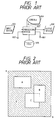
- a prior art apparatus for processing image data includes an image input device 601, an image data input terminal 602, and an image data processing device 603.
- the image input device 601 includes, for example, a scanner.
- the image input device 601 outputs image data to the image data processing device 603.
- Image data can be fed from an external device (not shown) to the image data processing device 603 via the image data input terminal 602.
- the image data processing device 603 includes a computer having a CPU, a RAM, and a storage device for storing a program.
- the image data processing device 603 operates in accordance with this program.
- the image data processing device 603 stores the input image data into an image data file device 605 including, for example, a magnetic disk.
- a console 604 is connected to the image data processing device 603.
- the console 604 includes a display or a monitor, and a manual operating device such as a keyboard and a mouse.
- the image data processing device 603 reads out image data from the image data file device 605 and then transfers the image data to the monitor in the console 604 so that the image data will be visualized on the monitor.
- the operator observes the reproduced image on the monitor, the operator actuates the operating device in the console 604 to input instructions of processing the reproduced image, for example, instructions of revising, changing, and editing the reproduced image.
- the input instructions are transmitted from the console 604 to the image data processing device 603.
- the image data processing device 603 processes the image data in compliance with the input instructions by referring to an image data processing segment of the program.
- the resultant image data are fed from the image data processing device 603 to the monitor in the console 604 so that the resultant image data will be visualized on the monitor.
- the resultant image data are output from the image data processing device 603 to an image output device 606.
- the resultant image data can be output from the image data processing device 603 to an external device (not shown) via an image data output terminal 607.
- Fig. 2 shows an example of conditions of indicated information on the monitor in the console 604.
- this example includes different images "A”, “B”, and “C” which respectively occupy regions within an editing area [a, b], that is, an editing rectangular area defined by opposing vertex points "a” and "b".
- a description will be given of editing the images "A”, “B”, and “C” into a composite image which fills the editing area [a, b].
- data having values equal to "0" are generated as initial data representing an initial image filling the editing area [a, b].
- the initial image data are processed into second image data by adding data of the image "A" to the initial image data.
- the second image data are similarly processed into third image data in response to data of the image "B”.
- the third image data are processed into final image data in response to data of the image "C”.
- the final image data represent an image which occupies the editing area [a, b] and which agrees with a resultant of editing the images "A”, "B", and "C”.
- the above-mentioned prior art method and apparatus have the following problems.
- In the case of editing two or more images into a composite image it is necessary to newly prepare an edited image data file in the image data file device 605.
- the resultant image has a hatched area which is represented by meaningless data "0".
- the meaningless data "0" occupies a part of an image memory within the image data processing device 603, so that the part of the image memory is wasted.
- EP-A-0,280,582 discloses a windowing system which controls window size and positioning by varying the mapping of the display memory.
- a first aspect of this invention provides a method of processing image data representative of at least first and second source images having respective overlap portions which overlap each other in indicated positions, the method comprising the steps of storing input source images as digital data; editing the digital data into edited image data; and outputting the edited image data; characterised in that the step of editing the digital data comprises: changing data in the overlap portion of said first image so as to represent both display information of the overlap portion of the first image and display information of the overlap portion of said second image and setting data of the overlap portion of said second image to a predetermined value.
- a second aspect of this invention provides an apparatus for processing image data representative of first and second images having respective overlap portions which overlap each other in indicated positions, the apparatus comprising:
- Fig. 1 is a block diagram of a prior art apparatus for processing image data.
- Fig. 2 is a diagram showing an example of an indicated composite image in the prior art apparatus of Fig. 1.
- Fig. 3 is a block diagram of an apparatus for processing image data according to an embodiment of this invention.
- Fig. 4 is a diagram showing an example of an indicated composite image in the apparatus of Fig. 3.
- Fig. 5 is a diagram showing source images subjected to an editing process.
- Fig. 6 is a diagram showing an example of an indicated composite image which occurs after an editing process is completed in the apparatus of Fig. 3.
- Fig. 7 is a diagram showing an example of an indicated composite image which occurs before an editing process is completed in the apparatus of Fig. 3.
- Fig. 8 is a flowchart of a part of a program operating the image data processing device in the apparatus of Fig. 3.
- Fig. 9 is a diagram showing image and conditions of data stored into the output buffer in the apparatus of Fig. 3.
- Fig. 10 is a flowchart of the data outputting segment of the program controlling the image data processing device in the apparatus of Fig. 3.
- an image data processing apparatus of this invention includes an image input device 101, an image data input terminal 102, and an image data processing device 103.
- the image input device 101 includes, for example, a scanner.
- the image input device 101 outputs image data to the image data processing device 103.
- Image data can be fed from an external device (not shown) to the image data processing device 103 via the image data input terminal 102.
- the image data processing device 103 includes a computer having a CPU, a RAM, and a storage device for storing a program.
- the image data processing device 103 operates in accordance with this program.
- the image data processing device 103 stores the input image data into an image data file device 105 including, for example, a magnetic disk.
- a console 104 is connected to the image data processing device 103.
- the console 104 includes a display or a monitor, and a manually operating device such as a keyboard and a mouse.
- the image data processing device 103 reads out image data from the image data file device 105 and then transfers the image data to the monitor in the console 104 so that the image data will be visualized on the monitor.
- the operator observes the reproduced image on the monitor, the operator actuates the operating device in the console 104 to input instructions of processing the reproduced image, for example, instructions of revising, changing, and editing the reproduced image.
- the input instructions are transmitted from the console 104 to the image data processing device 103.
- the image data processing device 103 processes the image data in compliance with the input instructions by referring to an image data processing segment of the program.
- the resultant image data are fed from the image data processing device 103 to the monitor in the console 104 so that the resultant image data will be visualized on the monitor.
- the resultant image data are output from the image data processing device 103 to an image output device 106.
- the resultant image data can be output from the image data processing device 103 to an external device (not shown) via an image data output terminal 107.
- the image data processing device 103 includes an image data memory 103A and an image data output buffer (an image data output buffer memory) 103B.
- the image data memory 103A is used to store data subjected to processing and visualized on the monitor in the console 104.
- the output buffer 103B is used to store data to be outputted.
- the image memory 103A and the output buffer 103B will be explained in detail later.
- Fig. 4 shows an example of conditions of a composite image which is represented by data output from the image data processing device 103 and obtained by an editing process.
- an area [a, b] defined by the broken lines that is, a rectangular area defined by opposing vertex points "a” and "b", agrees with an area of the composite image which results from the editing process.
- the composite image has sub images "A”, “B”, and “C” which are generated from original images (source images) through processing, layout, or synthesis.
- Portions of the composite image which extend outside the sub images "A”, “B”, and “C” are represented by data which are not stored in the image memory 103A and which are generated in the image data buffer 103B.
- the data of the portions of the composite image outside the sub images "A", “B”, and “C” are generated by clearing the output buffer 103B.
- the images “B” and “C” partially overlap each other, and the images “B” and “C” occupy a higher place and a lower place respectively.
- the overlap portion of the higher-place image “B” is represented by data which result from the editing process, while the overlap portion of the lower-place image “C” is represented by data of "0".
- the data representing the image "B” and the data representing the image “C” are managed independently of and separately from each other.
- Fig. 6 shows an example of the finally-obtained composite image which is indicated on the monitor in the console 104 or an external monitor under conditions where the data of the composite image are transferred in a sequence corresponding to a direction from the lowest image place to the highest image place.
- the overlap portion of the image "B" is represented by the data which result from the editing process, both the original information in the overlap portion of the image "B” and the original information in the overlap portion of the image "C" are accurately indicated.
- Fig. 7 shows an example of an intermediately-obtained image which is indicated on the monitor in the console 104 or an external monitor under conditions where the editing process has not yet been completed and where the data of the image are transferred in a sequence corresponding to a direction from the lowest image place to the highest image place.
- the original information in the overlap portion of the image "B" is indicated, but the original information in the overlap portion of the image "C” is not indicated.
- the non-indication of one of the original information represents that the editing process has not yet been completed.
- a decision as to whether or not the editing process has been completed can be performed by referring to the conditions of the indication of the overlap portions of the images.
- Fig. 8 is a flowchart of the editing segment of the program controlling the image data processing device 103.
- a first step 201 of the editing segment of the program prepares a management file in accordance with operator's instruction.
- the management file is designed so as to manage a plurality of sub images (source images or original images) to be edited.
- the management file is provided in the image data file device 105.
- a step 202 following the step 201 registers the names of the sub images and the indicated positions of the sub images in an output composite image with the management file.
- a step 203 following the step 202 controls the monitor in the console 104 so that a composite image will be generated on the monitor in response to the registered information of the sub images and the data of the sub images.
- the sub images are indicated on the monitor in a sequence according to an order of the indicated positions of the sub images in an overwriting manner.
- the composite image extends beyond the edges of the screen of the monitor, the composite image is contracted so that the whole of the composite image can be indicated on the monitor.
- the program advances to a step 204.
- the step 204 selects one or more of the sub images in accordance with operator's instruction. For example, the selected sub images agree with sub images overlapping each other, and the selected sub image agrees with a sub image to be edited.
- the step 204 transfers the information and data of the selected sub images to the image memory 103A.
- a step 205 following the step 204 controls the monitor in the console 104 so that the selected sub images will be indicated on the monitor.
- a step 206 following the step 205 edits the overlap portions of the selected sub images in compliance with operator's instruction. Specifically, as shown in Fig. 5, the data of the overlap portion of the higher-place image are changed so as to represent both the display information of the overlap portion of the higher-place image and the display information of the overlap portion of the lower-place image, while the data of the overlap portion of the lower-place image are cleared to "0".
- a step 207 following the step 206 transfers the information and data of the resultant edited sub images from the image memory 103A to the image file in the image data file device 105 so that the information and data of the resultant edited sub images will replace the information and data of the corresponding previous sub images in the image file.
- a step 208 following the step 207 decides whether or not the editing process is completed, that is, whether or not an image to be edited remains.
- the program advances from the step 208 to a step 209.
- the program returns from the step 208 to the step 204.
- the steps 204-208 are reiterated until the editing process is completed.
- the step 209 controls the monitor in the console 104 so that the resultant composite image will be reproduced on the monitor in response to the information and data of the edited sub images.
- the sub images are indicated on the monitor in a sequence according to indicated position.
- a step 210 following the step 209 decides whether operator's instruction represents acceptance or rejection of the indicated composite image.
- the program returns from the step 210 to the step 204.
- the editing segment of the program ends.
- the data of the finally-obtained composite image are outputted as follows.
- the data of the composite image which correspond to a scanning line "a" of Fig. 9 are outputted from the image data processing device 103, it is necessary to output both the data of the sub image "A" and the data of the sub image "B".
- the data of the lower-place image "B” are transferred to the portion of the output buffer 103B which extends between positions b1 and b2
- the data of the higher-place image "A” are transferred to the portion of the output buffer 103B which extends between positions a1 and a2 as shown in Fig. 9.
- the image data are transferred from the output buffer 103B to the image output device 106.
- the data in the output buffer 103B represent a correct composite image since the data of the overlap portion of the image "B” are previously changed so as to represent both the display information of the overlap portion of the image "B” and the display information of the overlap portion of the image "C”.
- Fig. 10 is a flowchart of the data outputting segment of the program controlling the image data processing device 103.
- a first step 301 of the data outputting segment of the program designates a management file, which is prepared in the editing process of Fig. 8, in response to operator's instruction.
- a step 302 following the step 301 numbers respective sub images in the management file by "i" in an order according to indicated position.
- a step 303 following the step 302 prepares an output line management table in response to the information of the indicated positions of the sub images.
- the output line management table contains an output starting line number Ysi, an output ending line number Yei, an output starting horizontal (X) position Xsi, and an output ending horizontal (X) position Xei for each sub image denoted by a number "i".
- an image to be output and its data are determined by referring to the output line management table.
- a step 304 following the step 303 prepares the image data output buffer 103B by, for example, using a portion of the RAM within the image data processing device 103.
- a step 305 following the step 304 initializes an output image line number "L". After the step 305, the program advances to a step 306.
- the step 306 refers to the output line management table, and thereby selects a number or numbers "i" denoting a sub image or sub images to be output at the current output line "L".
- the step 306 generates a set ⁇ i ⁇ L of the selected number or numbers "i”.
- a step 307 following the step 306 compares the set ⁇ i ⁇ L with the set ⁇ i ⁇ L-1 which was generated with respect to the preceding output line "L-1". This comparison is to detect whether the set ⁇ i ⁇ L has changed from the preceding set ⁇ i ⁇ L-1 or remains unchanged, that is, whether or not there occur a new sub image to be outputted at the current line "L” and the sub image which should cease from being output at the current output line "L".
- the program advances from the step 307 to a step 308.
- the program advances from the step 307 to a step 310.
- the step 308 sets an image line number Yi for the new sub image detected by the preceding step 307.
- the step 308 initializes the image line number Yi to 1.
- the image line number Yi is independently set for each of the respective sub images.
- a step 309 following the step 308 clears the output buffer 103B. After the step 309, the program advances to the step 310.
- the step 310 transfers the line data of the image line number Yi of each sub image to the area of the output buffer 103B which extends between positions corresponding to the output starting horizontal position Xsi and the output ending horizontal position Xei.
- the line data of the sub images are transferred in a sequence according to vertical indicated position.
- the step 310 increments the image line number Yi which corresponds to the image number "i", the transfer of which is completed.
- a step 311 following the step 310 decides whether or not the transfer of the data of all the sub images is completed. When the transfer of the data of all the sub images is not completed, the program returns from the step 311 to the step 310 so that the step 310 will be reiterated. When the transfer of the data of all the sub images is completed, the program advances from the step 311 to a step 312.
- the step 312 transfers the data from the output buffer 103B to the image output device 106.
- a step 314 following the step 313 decides whether or not the output line "L” agrees with a predetermined final line. When the output line "L” disagrees with the final line, the program returns from the step 314 to the step 306. When the output line "L” agrees with the final line, the data outputting segment of the program ends.
Landscapes
- Chemical & Material Sciences (AREA)
- Organic Chemistry (AREA)
- Physics & Mathematics (AREA)
- General Physics & Mathematics (AREA)
- Engineering & Computer Science (AREA)
- Theoretical Computer Science (AREA)
- Inorganic Chemistry (AREA)
- Processing Or Creating Images (AREA)
- Image Processing (AREA)
Claims (6)
- Procédé de traitement de données d'image représentatives d'au moins des première et deuxième images-sources comportant des parties de recouvrement respectives qui se recouvrent mutuellement dans des positions indiquées, le procédé comprenant les étapes consistant à stocker des images-sources d'entrée en tant que données numériques; modifier les données numériques en les transformant en données d'image modifiées; et à émettre les données d'image modifiées; caractérisé en ce que l'étape de modification des données numériques consiste:à changer les données dans la partie de recouvrement de ladite première image de manière qu'elle représentent à la fois des informations de la partie de recouvrement de la première image et des informations d'affichage de la partie de recouvrement de ladite deuxième image et à établir les données de la partie de recouvrement de ladite deuxième image à une valeur prédéterminée.
- Procédé selon la revendication 1, dans lequel ladite valeur prédéterminée est une valeur nulle.
- Procédé selon la revendication 2 ou 3, comprenant en outre l'étape consistant à sélectionner deux images-sources parmi une pluralité d'images-sources en tant que la première image et la deuxième image en réponse aux positions indiquées de ces dernières.
- Appareil pour traiter des données d'image représentatives des première et deuxième images comportant des parties de recouvrement respectives qui se recouvrent mutuellement dans des positions indiquées, l'appareil comprenant:un moyen (103) destiné à changer des données de la partie de recouvrement de la première image de manière qu'elles représentent à la fois des informations d'affichage de la partie de recouvrement de la première image et des informations d'affichage de la partie de recouvrement de la deuxième image pour générer ainsi des données représentatives d'une troisième image, ladite troisième image correspondant à la première image dans les parties qui ne se recouvrent pas et une combinaison des première et deuxième images dans les parties qui se recouvrent; etun moyen (103B) pour émettre les données de la troisième image et les données de la quatrième image.
- Appareil selon la revendication 4, dans lequel le moyen de traitement comprend un moyen pour établir les données de la partie de recouvrement de la deuxième image à une valeur nulle.
- Appareil selon la revendication 4 ou 5, dans lequel le moyen d'émission comprend une mémoire tampon de sortie (103B), un premier moyen d'écriture pour inscrire les données de la quatrième image dans la mémoire tampon de sortie, un deuxième moyen d'écriture pour, après que le premier moyen d'écriture à inscrit les données de la quatrième image dans la mémoire tampon de sortie, inscrire les données de la troisième image dans la mémoire tampon de sortie et inscrire des données d'une partie de recouvrement de la troisième image sur des données d'une partie de recouvrement de la quatrième image, et un moyen pour émettre les données de la quatrième image et les données de la troisième image provenant de la mémoire tampon de sortie (103B).
Applications Claiming Priority (2)
| Application Number | Priority Date | Filing Date | Title |
|---|---|---|---|
| JP143097/90 | 1990-05-31 | ||
| JP2143097A JP2584105B2 (ja) | 1990-05-31 | 1990-05-31 | 画像編集処理方法 |
Publications (3)
| Publication Number | Publication Date |
|---|---|
| EP0459711A2 EP0459711A2 (fr) | 1991-12-04 |
| EP0459711A3 EP0459711A3 (en) | 1993-08-04 |
| EP0459711B1 true EP0459711B1 (fr) | 1998-07-15 |
Family
ID=15330843
Family Applications (1)
| Application Number | Title | Priority Date | Filing Date |
|---|---|---|---|
| EP91304707A Expired - Lifetime EP0459711B1 (fr) | 1990-05-31 | 1991-05-24 | Méthode et appareil de traitement de données d'image |
Country Status (3)
| Country | Link |
|---|---|
| EP (1) | EP0459711B1 (fr) |
| JP (1) | JP2584105B2 (fr) |
| DE (1) | DE69129776T2 (fr) |
Families Citing this family (11)
| Publication number | Priority date | Publication date | Assignee | Title |
|---|---|---|---|---|
| JP2750411B2 (ja) * | 1992-12-02 | 1998-05-13 | 大日本スクリーン製造株式会社 | 製版処理装置 |
| JPH0711448A (ja) * | 1993-06-29 | 1995-01-13 | Ishihara Chem Co Ltd | 銅系素材選択型無電解めっき用触媒液 |
| US5485562A (en) * | 1993-09-14 | 1996-01-16 | International Business Machines Corporation | System and method for clipping pixels drawn in one of plurality of windows in a computer graphics system |
| AUPM822194A0 (en) * | 1994-09-16 | 1994-10-13 | Canon Inc. | Utilisation of scanned images in an image compositing system |
| US5930813A (en) * | 1995-12-21 | 1999-07-27 | Adobe Systems Incorporated | Method and system for designating objects |
| US5764229A (en) * | 1996-05-09 | 1998-06-09 | International Business Machines Corporation | Method of and system for updating dynamic translucent windows with buffers |
| US6046748A (en) * | 1996-06-27 | 2000-04-04 | Peerless Systems Corporation | Cooperative filter and raster operation evaluation model |
| US5815645A (en) * | 1996-07-29 | 1998-09-29 | Eastman Kodak Company | Method of combining two digital images |
| US6856421B1 (en) | 1997-09-30 | 2005-02-15 | Hewlett-Packard Indigo B.V. | Page composition system |
| JP4582977B2 (ja) * | 2001-12-06 | 2010-11-17 | プレステク,インコーポレイテッド | 最適化されたイメージ処理の方法及び装置 |
| JP6268891B2 (ja) | 2013-10-07 | 2018-01-31 | セイコーエプソン株式会社 | コラージュ画像作成プログラム、コラージュ画像作成方法、及びコラージュ画像作成装置 |
Family Cites Families (2)
| Publication number | Priority date | Publication date | Assignee | Title |
|---|---|---|---|---|
| JPS6228790A (ja) * | 1985-07-31 | 1987-02-06 | 富士通株式会社 | 格納域アクセス方式 |
| JPS6414678A (en) * | 1987-02-27 | 1989-01-18 | Kiyapuran Saibaneteitsukusu Co | Cpmputer graphic system |
-
1990
- 1990-05-31 JP JP2143097A patent/JP2584105B2/ja not_active Expired - Fee Related
-
1991
- 1991-05-24 DE DE69129776T patent/DE69129776T2/de not_active Expired - Fee Related
- 1991-05-24 EP EP91304707A patent/EP0459711B1/fr not_active Expired - Lifetime
Also Published As
| Publication number | Publication date |
|---|---|
| JPH0436877A (ja) | 1992-02-06 |
| EP0459711A2 (fr) | 1991-12-04 |
| DE69129776D1 (de) | 1998-08-20 |
| JP2584105B2 (ja) | 1997-02-19 |
| EP0459711A3 (en) | 1993-08-04 |
| DE69129776T2 (de) | 1998-12-03 |
Similar Documents
| Publication | Publication Date | Title |
|---|---|---|
| EP0459711B1 (fr) | Méthode et appareil de traitement de données d'image | |
| JPS6255137B2 (fr) | ||
| JPH0640219B2 (ja) | 切り抜きマスクデータの作成方法 | |
| US6122069A (en) | Efficient method of modifying an image | |
| JP3059867B2 (ja) | ソリッドモデル修正方法およびソリッドモデル生成装置 | |
| JP3792418B2 (ja) | 画像処理方法およびその装置 | |
| JPH0546718A (ja) | 画像編集装置 | |
| JP3466813B2 (ja) | 画像検証装置 | |
| JP2825273B2 (ja) | 図面管理方法及び装置 | |
| JP2825927B2 (ja) | 画像処理装置 | |
| JP2910237B2 (ja) | 文字編集支援装置 | |
| JP3153481B2 (ja) | 回路図管理システム | |
| JP2779522B2 (ja) | 多角形の入力方法 | |
| JP2721344B2 (ja) | 画像処理方法 | |
| JPH08263652A (ja) | 図形編集装置 | |
| JP2642167B2 (ja) | 数値制御データ作成方法 | |
| JPH031215A (ja) | 多重領域入力装置 | |
| JPH11265456A (ja) | ラスターデータ生成方法及びその装置 | |
| JPH09319855A (ja) | 地図作成装置及び方法 | |
| JPH0785237A (ja) | 画像編集方法およびその装置 | |
| JPH0589103A (ja) | 文書編集処理装置 | |
| JP2000003375A (ja) | Cad装置 | |
| JPH09282356A (ja) | 論理回路修正方式 | |
| JPH10173904A (ja) | ディジタルデータ修正装置 | |
| JPH0548877A (ja) | 複写機 |
Legal Events
| Date | Code | Title | Description |
|---|---|---|---|
| PUAI | Public reference made under article 153(3) epc to a published international application that has entered the european phase |
Free format text: ORIGINAL CODE: 0009012 |
|
| 17P | Request for examination filed |
Effective date: 19910604 |
|
| AK | Designated contracting states |
Kind code of ref document: A2 Designated state(s): DE FR GB |
|
| PUAL | Search report despatched |
Free format text: ORIGINAL CODE: 0009013 |
|
| AK | Designated contracting states |
Kind code of ref document: A3 Designated state(s): DE FR GB |
|
| 17Q | First examination report despatched |
Effective date: 19961111 |
|
| GRAG | Despatch of communication of intention to grant |
Free format text: ORIGINAL CODE: EPIDOS AGRA |
|
| GRAG | Despatch of communication of intention to grant |
Free format text: ORIGINAL CODE: EPIDOS AGRA |
|
| GRAH | Despatch of communication of intention to grant a patent |
Free format text: ORIGINAL CODE: EPIDOS IGRA |
|
| GRAH | Despatch of communication of intention to grant a patent |
Free format text: ORIGINAL CODE: EPIDOS IGRA |
|
| GRAA | (expected) grant |
Free format text: ORIGINAL CODE: 0009210 |
|
| AK | Designated contracting states |
Kind code of ref document: B1 Designated state(s): DE FR GB |
|
| PG25 | Lapsed in a contracting state [announced via postgrant information from national office to epo] |
Ref country code: FR Free format text: LAPSE BECAUSE OF FAILURE TO SUBMIT A TRANSLATION OF THE DESCRIPTION OR TO PAY THE FEE WITHIN THE PRESCRIBED TIME-LIMIT Effective date: 19980715 |
|
| REF | Corresponds to: |
Ref document number: 69129776 Country of ref document: DE Date of ref document: 19980820 |
|
| EN | Fr: translation not filed | ||
| PLBE | No opposition filed within time limit |
Free format text: ORIGINAL CODE: 0009261 |
|
| STAA | Information on the status of an ep patent application or granted ep patent |
Free format text: STATUS: NO OPPOSITION FILED WITHIN TIME LIMIT |
|
| 26N | No opposition filed | ||
| REG | Reference to a national code |
Ref country code: GB Ref legal event code: IF02 |
|
| PGFP | Annual fee paid to national office [announced via postgrant information from national office to epo] |
Ref country code: DE Payment date: 20030605 Year of fee payment: 13 |
|
| PG25 | Lapsed in a contracting state [announced via postgrant information from national office to epo] |
Ref country code: DE Free format text: LAPSE BECAUSE OF NON-PAYMENT OF DUE FEES Effective date: 20041201 |
|
| PGFP | Annual fee paid to national office [announced via postgrant information from national office to epo] |
Ref country code: GB Payment date: 20050518 Year of fee payment: 15 |
|
| PG25 | Lapsed in a contracting state [announced via postgrant information from national office to epo] |
Ref country code: GB Free format text: LAPSE BECAUSE OF NON-PAYMENT OF DUE FEES Effective date: 20060524 |
|
| GBPC | Gb: european patent ceased through non-payment of renewal fee |
Effective date: 20060524 |