EP0461400A2 - Textverarbeitungsgerät - Google Patents
Textverarbeitungsgerät Download PDFInfo
- Publication number
- EP0461400A2 EP0461400A2 EP91107630A EP91107630A EP0461400A2 EP 0461400 A2 EP0461400 A2 EP 0461400A2 EP 91107630 A EP91107630 A EP 91107630A EP 91107630 A EP91107630 A EP 91107630A EP 0461400 A2 EP0461400 A2 EP 0461400A2
- Authority
- EP
- European Patent Office
- Prior art keywords
- data
- textual data
- entered
- key
- stored
- Prior art date
- Legal status (The legal status is an assumption and is not a legal conclusion. Google has not performed a legal analysis and makes no representation as to the accuracy of the status listed.)
- Granted
Links
Images











Classifications
-
- G—PHYSICS
- G06—COMPUTING OR CALCULATING; COUNTING
- G06F—ELECTRIC DIGITAL DATA PROCESSING
- G06F40/00—Handling natural language data
- G06F40/10—Text processing
- G06F40/166—Editing, e.g. inserting or deleting
-
- G—PHYSICS
- G06—COMPUTING OR CALCULATING; COUNTING
- G06F—ELECTRIC DIGITAL DATA PROCESSING
- G06F15/00—Digital computers in general; Data processing equipment in general
- G06F15/02—Digital computers in general; Data processing equipment in general manually operated with input through keyboard and computation using a built-in program, e.g. pocket calculators
- G06F15/025—Digital computers in general; Data processing equipment in general manually operated with input through keyboard and computation using a built-in program, e.g. pocket calculators adapted to a specific application
- G06F15/0283—Digital computers in general; Data processing equipment in general manually operated with input through keyboard and computation using a built-in program, e.g. pocket calculators adapted to a specific application for data storage and retrieval
Definitions
- the present invention relates to improvements in small electronic apparatus having a text processing means and a storage means for storing input textual data.
- the invention also relates to a small electronic apparatus such as a so-called electronic organizer or the like, and more particularly to a small electronic apparatus having a plurality of modes each controlling specific data.
- the invention relates to a small electronic apparatus capable of storing various kinds of input data.
- Some of small electronic apparatus currently in wide use are capable of inputting text from the attached keyboard and storing the thus input text.
- a variety of documents ranging from materials for a conference to materials for presiding at a wedding reception, etc. are written using such small electronic apparatus. Most of such documents naturally are organized in a hierarchical structure.
- the hierarchical structure of a document consists specifically of a title, a plurality of subjects or items under the title, and a detailed description under each subject or item. It is often possible to subdivide the description under one subject or item into a plurality of portions according to the content.
- the hierarchical structure of text as mentioned above can be shown on the display thereof by the user's efforts such as providing indentations, item numbers, etc.
- the text is expressed by one-dimensional strings of character codes within the electronic apparatus, it has not been possible to process the text in accordance with the hierarchical structure the way that the user intended. For example, in order to delete a part relating to a certain subject from the input text, it has been necessary to specify the part to be deleted while checking the subject and the description relating to the subject on the display. Since the display provided on a small electronic apparatus is usually very small, such deletion work has been cumbersome particularly when the part to be deleted is long.
- electronic apparatus such as electronic organizers usually provide a plurality of modes in which to achieve a telephone book function, a schedule organizing function, a memo function, etc.
- Each of these modes is often provided with a data search function to facilitate retrieval of destination data from a large amount of data placed under the control of the mode.
- a data search function to facilitate retrieval of destination data from a large amount of data placed under the control of the mode.
- the telephone book mode is selected, and then, a prescribed key operation is performed to specify the execution of data search.
- a key character string used in data Search hereinafter called the "search character string"
- search character string a key character string used in data Search
- Data retrieval can thus be performed on the telephone book data in the telephone book mode, for example.
- data retrieval if data containing the same search character string is to be retrieved from the schedule data, for example, it has been necessary to move from the telephone book mode to the schedule mode and reenter the search character string from the keyboard. Therefore, with prior art electronic apparatus, data retrieval has had to be performed independently in each mode. In other words, it has not been possible to use the search character string entered in the current mode for retrieval of data that is under the control of a different mode; data retrieval in that different mode has only been possible by reentering the search character string after moving to that mode.
- small electronic apparatus such as the so-called electronic organizers are designed to be capable of performing various functions.
- data items such as the company name, the department name, the telephone number, the person's name, etc. can be entered from the keyboard and can be stored in the electronic organizer. The stored data can be retrieved for display on the display.
- clip board provided in a certain type of electronic organizer.
- data must be previously put in the clip board (that is, data must be previously stored in the memory area assigned to the clip board); otherwise, the data cannot be used for later data input.
- Another object of the invention is to provide a small electronic apparatus capable of performing a flexible data search between different modes without repeatedly entering a search character string.
- a further object of the invention is to provide a small electronic apparatus free from cumbersome key operations and having less possibility of erroneous data input even when entering the same data repeatedly.
- the invention provides a small electronic apparatus having text creating means and storage means for storing textual data entered using the text creating means, the text creating means comprising: means for selecting one of hierarchical levels in accordance with the operation by the operator; and means for managing the textual data entered and stored in the storage means by relating it to the selected hierarchical level.
- the invention also provides a small electronic apparatus having text creating means having more than one text processing function and storage means for storing textual data entered using the text creating means, the text creating means comprising: means for selecting one of hierarchical levels in accordance with the operation by the operator; means for managing the textual data entered and stored in the storage means by relating it to the selected hierarchical level; means for selecting one of the stored textual data in accordance with the operation by the operator; and means for performing any one of the text processing functions by handling as one block the textual data selected by the textual data selecting means and the textual data related to a lower hierarchical level directly or indirectly subordinate to the hierarchical level of the selected textual data on the basis of the management information held in the managing means.
- the invention provides a still another small electronic apparatus having text creating means, storage means for storing textual data entered using the text creating means, and data processing means other than the text creating means, the text creating means comprising: means for selecting one of hierarchical levels in accordance with the operation by the operator; means for managing the textual data entered and stored in the storage means by relating it to the selected hierarchical level; means for selecting one of the stored textual data in accordance with the operation by the operator; and means for storing the textual data selected by the textual data selecting means, together with the textual data related to a lower hierarchical level directly or indirectly subordinate to the hierarchical level of the selected textual data, into storage means accessible by that other data processing means on the basis of the management information held in the managing means.
- the invention further provides a small electronic apparatus having text creating means, storage means for storing textual data entered using the text creating means, and display means for displaying the textual data stored in the storage means, the text creating means comprising: means for selecting one of hierarchical levels in accordance with the operation by the operator; means for managing the entered textual data by relating it to the selected hierarchical level; means for selecting one of the stored textual data in accordance with the operation by the operator; and means for displaying the selected textual data, together with the textual data belonging to a hierarchical level coordinate with the hierarchical level of the selected textual data and subordinate to a higher hierarchical level to which the hierarchical level of the selected textual data is subordinate, on the display means on the basis of the management information held in the managing means.
- a small electronic apparatus capable of creating text having a hierarchical structure and of manipulating the created text in accordance with the hierarchical structure thereof. Also, in the small electronic apparatus of the invention, just by specifying certain textual data in a piece of text as a candidate for text processing, the textual data directly or indirectly subordinate to the specified textual data is automatically included as a candidate for processing; thus, the candidate for processing can be selected effectively and correctly when processing text having a hierarchical structure. Furthermore, in the small electronic apparatus of the invention, it is possible to display only the textual data related to a certain hierarchical level, omitting from the display the textual data related to lower hierarchical levels than that level. This helps to grasp the whole text structure even when the size of the display device provided in the electronic apparatus is limited. To sum up, with the small electronic apparatus of the invention, it is possible to create text intrinsically having a hierarchical structure.
- the invention provides a small electronic apparatus having a plurality of modes each controlling specific data, comprising: means for designating a desired character string from among the data under control of one of the plurality of modes; means for storing the designated character string; and means for retrieving data containing the stored character string from among the data under control of another mode.
- an easy-to-use small electronic apparatus capable of performing a flexible data search between a plurality of different modes without repeatedly entering a search character string.
- the invention also provides a small electronic apparatus having data input means, storage means for storing input data, and display means for displaying the data stored in the storage means, comprising: means for displaying on the display means a group of data having a prescribed relationship to data to be input from the data input means; means for selecting data from the group of data displayed; and means for determining the selected data as the data to be input.
- a small electronic apparatus in which data can be entered effectively by a simple key operation using already entered data when the data to be entered is identical to the already entered data.
- Fig.1 shows an external view of a small electronic apparatus in one embodiment of the invention.
- the small electronic apparatus 1 of Fig.1 consists of a main body 2 and a main body cover 3, the main body 2 having a keyboard 4.
- the keyboard 4 comprises a mode selector section 41, which includes keys for selecting modes, an operation instruction section 42, which includes a power key, function keys for performing various operations (including an "insert” key, a "select” key, and a “call” key), and cursor keys, and a data input section 43, which includes character keys for entering character data and numeric keys for entering numeric data.
- a liquid crystal display (LCD) 5 capable of displaying a plurality of lines and a transparent keyboard 6.
- LCD liquid crystal display
- Other types of display device having a low power dissipation may be used instead of the LCD 5.
- a memory card hereinafter described is inserted into position through a slot (not shown) near the hinge on the back of the main body cover 3 in such a manner that the front face of the memory card can be seen through the transparent keyboard 6.
- the transparent keyboard 6 is used when executing an application program supplied by the memory card.
- the memory card 7 comprises a ROM 71 for storing an application program, a RAM 72 for storing variable information generated during the execution of the application program, a female connector 73 for connecting the ROM 71 and the RAM 72 to the small electronic apparatus 1, and a backup battery 74 for retaining information stored in the RAM 72.
- the application program stored in the ROM 71 is the type that does not generate variable information during the execution thereof, there is no need to provide the RAM 72 or the battery 74.
- key symbols unique to the application program in the memory card 7 are printed on the front face of the memory card 7.
- the key symbols do not have the functions as keys, and actual key entries are made using the transparent keyboard 6.
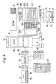
- FIG.4 shows the hardware configuration of the small electronic apparatus 1.
- a control section 8 for controlling the small electronic apparatus 1 contains a CPU 81 and a gate array 82.
- the LCD 5 shown in Fig.1 is connected to the control section 8 via a decoder 51, a bit map memory 52, a common driver 53, and a segment driver 54.
- the data to be displayed on the LCD 5 is supplied from the control section 8 to the decoder 51.
- the decoder 51 decodes the data and writes it into the bit map memory 52.
- the bit map memory 52 is a memory in which one bit is assigned to every dot of the LCD 5, the bits corresponding to the dots to illuminate being set to "1" and the other bits being set to "0".
- the common driver 53 and the segment driver 54 are used to display characters, graphics, etc. on the LCD 5 according to the contents stored in the bit map memory 52.
- the reference numeral 45 shows a key matrix for detecting key entries from the keyboard 4, while the reference numeral 65 indicates a key matrix for detecting key entries from the transparent keyboard 6.
- the ROM 9 stores a basic program for performing basic functions including handling of data input from the keyboard 4 and the transparent keyboard 6 and displaying on the LCD 5; application programs for performing a calendar display function, an address book function, a text creation function, a schedule management function, and a memo function; and a plurality of tables having fixed contents and used in application programs for calendar display, etc.
- the RAM 10 is used to store variable information needed by the application programs stored in the RON 9.
- the RAM 10 has an address book memory area 101, a schedule memory area 102, a memo data memory area 103, a table 104 for managing the information relating to the memo data stored in the memo data memory area 103, a mode memory area 105 for storing the various modes, a textual data memory area 106, a management table 107 for managing hierarchical relationships, etc. of the textual data stored in the text memory area 106, and a data exchange memory area 110 for exchanging data between the application programs.
- the RAM 10 also has areas for storing various variables, pointers, and flags.
- a real time clock (RTC) 11, an expansion terminal (I/O) 12 for connecting an external device such as a printer, and an expansion terminal (I/O) 13 dedicated for a memory card are connected to the control section 8.
- RTC real time clock
- I/O expansion terminal
- I/O 13 dedicated for a memory card
- Connected to the expansion terminal (I/O) 13 are a male connector 14 to which the female connector 73 of the memory card 7 is connected and a detector 15 for detecting the connection of the male connector 14 to the female connector 73 of the memory card 7.
- Fig.5 shows the memory map of the small electronic apparatus 1.
- the addresses of the small electronic apparatus 1 are assigned to the internal ROM 9 of the electronic apparatus 1, the internal RAM 10 of the electronic apparatus 1, and the internal memory device of the memory card 7, in this order. Since the ROM 9 and the RAM 10 have fixed capacities, the addresses assigned to them are fixed.
- addresses starting at the address next to the last address of the internal RAM 10 of the electronic apparatus 1 are assigned to the internal memory device of the memory card 7 (the internal memory device consists of the ROM 71 and the RAM 72 or only of the ROM 71).
- the capacity of the internal memory device of the memory card 7 may vary from card to card. This means that the last address assigned to the internal memory device of the memory card may vary from card to card. However, the high limit of the last address is determined by the specification of the control section 8.
- Fig.6 shows the mode selector section 41 having six mode selector keys 41a to 41f.
- the mode selector keys 41a to 41e are used to start the application programs stored in the internal ROM 9 of the small electronic apparatus 1, while the mode selector key 41f is used to start the application program of the memory card 7 loaded into the small electronic apparatus 1.
- each section of the small electronic apparatus 1 is initialized (step s1), getting ready for the depression of the mode selector keys 41a to 41f (step s2).
- step s1 When any one of the mode selector keys is depressed, the application program corresponding to the depressed mode selector key is started (steps S3-S8). Even when one application program has been started, any other application program can be started by depressing the corresponding mode selector key 41a to 41f.
- the mode selector key 41a is depressed to start the calendar program (step s3).
- the calendar program is primarily for displaying a calendar for the month to which the current date belongs.
- the mode selector key 41b is depressed to start the address book program (step s4).
- the address book program allows the creation of an address book in which the person's name, the telephone number, and the address are stored as a set of data. By entering the name of the person whose telephone number and/or address are needed, the required information can be retrieved from the address book.
- the mode selector key 41c is depressed to start the next creation program (step s5).
- the text creation program it is possible to create and manipulate text having a hierarchical structure, as detailed hereinafter.
- the mode selector key 41d is depressed to start the schedule program (step s6).
- the schedule program it is possible to create a table of schedule data each consisting of date and schedule item and retrieve future schedule data nearest to the current date from the schedule table.
- the mode selector key 41e is depressed to start the memo program (step s7). Using the memo program, it is possible to input memo data and display the input memo data.
- the detector 15 When the mode selector key 41f is depressed, the detector 15 is activated which electrically detects the connection of the female connector 73 of the memory card 7 to the male connector 14 of the small electronic apparatus 1, to check whether the memory card 7 is loaded or not. When it is decided that the memory card 7 is not loaded, the depression of the mode selector key 41f is disabled. On the other hand, when it is decided that the memory card 7 is loaded, the application program contained in the internal ROM 71 of the memory card 7 is started.
- Fig.8 shows how textual data is managed by the text creation program.
- Textual data entered is stored in the textual data memory area 106 in the RAM 10 in the same order that it is arranged in the entire text. Individual pieces of textual data stored in the textual data memory area 106 are separated from each other by a delimiter not shown.
- each textual data is assigned a hierarchical level, under direct subordination to which more than one textual data belonging to a hierarchy one level lower than that of the above textual data can be placed.
- the textual data stored in the textual data memory area 106 is organized in a tree-structured hierarchical relationship.
- the hierarchical relationship of the textual data stored in the textual data memory area 106 is managed using the management table 107.
- the management table 107 has a plurality of fixed-length entries 108.
- the arrow marks extending from the entries 108 to the textual data memory 106 area indicate the correspondence of the entries 108 of the management table 107 relative to the textual data.
- the entries 108 of the management table 107 are arranged in the management table 107 in accordance with the order in which the textual data is stored in the textual data memory area 106.
- Each entry 108 of the management table 107 consists of a hierarchy field 111, a child existence flag 112, and a character number field 113.
- a binary number representing the hierarchy of the textual data corresponding to the entry 108 is stored in the hierarchy field 111.
- a higher level of hierarchy is represented by a smaller value.
- the highest level of hierarchy represented by the binary number "0000” is dedicated to the title of text.
- the hierarchical levels represented by the binary numbers "0001", “0010”, and "0011” are assigned to the textual data classified as "major item”, “medium item”, and “minor item", respectively. It is also possible to input textual data belonging to a lower hierarchical level than that of the minor item.
- the child existence flag 112 is set to "1" when textual data directly subordinate to the textual data corresponding to the entry 108 exists, and to "0" when such textual data does not exist.
- the number of characters contained in the textual data corresponding to the entry 108 is stored in the character number field 113.
- the entries 108 of the management table 107 are arranged in the management table 107 in accordance with the order in which the textual data is stored in the textual data memory area 106, as previously mentioned, there is no need to provide a pointer chain between the entries 108 for explicitly pointing to the tree-structure hierarchical relationship.
- a table pointer 109 is a pointer that points to the entry 108 of the management table 107, and the entry 108 pointed to by the table pointer 109 is changed as the text creating and editing work by the text creation program progresses, as described hereinafter.
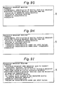
- a message as shown in Fig.9A is displayed prompting the operator to enter the title of the text to be created.
- Fig.9B shows the display when the character data "Facsimile broadcast receiver" has been entered as the title.
- a mark 91 is blinking at the position indented by one character on the line next to the title line, prompting the operator to enter a major item.
- the operator is notified of the hierarchical level of the textual data by the position of the mark 91 on the line.
- the hierarchical levels of the medium and minor items are indicated by the indentations by two and three characters, respectively.
- the entered title (textual data) is stored at the top of the textual data memory area 106, as shown in Fig.8.
- Hierarchical information "0000” and character number "00001011” (11 in decimal notation) are written into the entry 108 of the management table 107 corresponding to the title.
- the child existence flag 112 of the entry 108 is always set at "1" in the case of the title of text.
- Fig.9C shows the display after four major items have been entered.
- the entered major items are stored in the textual data memory area 106, part of which is shown in Fig.8.
- the entries 108 corresponding to the major items are created in the management table 107. "0001" is written into the hierarchy field 111 of each of these entries 108.
- the number of characters of each major item is stored in the character number field 113 of the corresponding entry 108.
- the child existence flag 112 is set to "0" since there is no textual data (medium item) subordinate to the major items when the major items are entered.
- the child existence flag 112 is set to "1" when a subordinate medium item is entered.
- a blinking mark 92 is displayed on the next line at the same indented position as that of the mark 91 for that major item, prompting the operator to enter the next major item.
- the hierarchical level of the textual data to be entered can be changed by moving the blinking mark using a cursor key.
- a cursor key is operated to select the major item corresponding to the parent of the medium item to be entered.
- the selected major item is indicated by a blinking mark 93 as shown in Fig.9D.
- a new line is inserted on which only a blinking mark 94 is displayed, as shown in Fig.9E.
- the mark 94 is displayed with the same indentation as that of the mark 93 attached to the selected major item.
- the mark 94 is moved one character to the right using a cursor key (Fig.9F).
- the mark 93 attached to the major item one line above the inserted line changes from a white to a blacked-out mark.
- a white mark indicates that there is no textual data subordinate to the textual data corresponding to that mark
- a black mark indicates that there is textual data subordinate to the textual data corresponding to that mark.
- the shape of the mark may be changed to indicate the presence or absence of subordinate textual data.
- Fig.9G shows the display after two medium items "Outline of the prototype receiver” and "Reception characteristics" have been entered.
- the input of the second medium item “Reception characteristics” is also accomplished by inserting a new line using the "insert” key.
- the entered medium items are stored in the textual data memory area 106 of Fig.8.
- the entries 108 corresponding to the medium items are created in the management table 107, and appropriate data is written into the created entries 108. Also, since the subordinate medium items are entered, "1" is written into the child existence field 112 of the entry 108 corresponding to the major item "Prototype"
- a minor item can be entered using a procedure similar to that for entering a medium item (Fig.9H).
- Fig.9I shows the display after all inputs have been made.
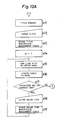
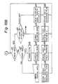
- a message is displayed prompting the operator to enter a title (step s11).
- the title is entered.
- the entered title is stored in the textual data memory area 106, appropriate data being written into the title entry 108 in the management table 107 (step s13).
- the number "1" representing the major item is substituted for a variable A indicating the hierarchy.
- a new line is started with a blinking mark displayed (step s15). Also, the table pointer 109 is updated so as to point to the next entry 108 (step s16).
- step s17 it is checked whether a character key or a numeric key is operated for entry of textual data; if it is decided that a character key or a numeric key has been operated, the process proceeds to step s18, and if not, the process proceeds to step s21 of Fig.10B.
- step s18 a major item is entered. The entered major item is stored in the textual data memory area 106, appropriate data being written into the entry 108 of the management table 107 pointed to by the table pointer 109 (step s19). When the processing of step s19 is completed, the process returns to step s15.
- step s21 (Fig.10B) it is checked whether a cursor key is depressed; if it is decided that a cursor key has been depressed, the process proceeds to step s22, and if not, the process proceeds to step s27.
- step s22 it is checked whether the depressed cursor key is an up/down key or a right/left key, and the process proceeds to step s23 in the case of an up/down key and to step s25 in the case of a right/left key.
- the mark to blink is changed according to the kind of the depressed cursor key.
- the table pointer 109 is updated according to the kind of the depressed cursor key, and the variable A is updated according to the contents of the hierarchy field 111 of the entry 108 pointed to by the updated table pointer 109. Thereafter, the process returns to step s21.
- step s25 the blinking mark is moved to the right or left according to the kind of the depressed cursor key, updating the variable A accordingly.
- step s26 the child existence flag 112 of the entry 108 is updated which is related to the textual data corresponding to the direct parent of the textual data to be entered after the blinking mark.
- Such an entry 108 can be easily located by searching the management table upward from the position pointed to by the table pointer 109. Thereafter, the process returns to step s21.
- step s27 it is checked whether the depressed key is the "insert” key or not; if it is determined as the "insert” key, the process proceeds to step s28, and if not, the process proceeds to S31.
- step s28 a new line is inserted.
- a blinking mark is displayed at the position on the inserted line in accordance with the value of the variable A (step s29).
- step 30 the table pointer 109 is updated so as to point to the next entry 108.
- the contents of all the entries after the entry 108 pointed to by the updated table pointer 109 are shifted by one entry. Thereafter, the process returns to step s21.
- step s31 textual data is entered.
- step s32 the entered textual data is stored in the textual data memory area 106.
- the location in the textual data memory area of the entered textual data is determined by adding up the values of the character number fields 113 of all entries that come before the entry 108 pointed to by the table pointer 109. Alternatively, a separate pointer may be provided for the textual data memory area 106.
- appropriate data is written into the entry 108 of the management table 107 pointed to by the table pointer 109.
- the value of the variable A is written into the hierarchy field 111 of the entry 108.
- the selected textual data and the textual data belonging to the hierarchy directly or indirectly subordinate to the hierarchy of the selected textual data can be processed en bloc for deletion, moving, or copying, as well as for copying to the data exchange memory area 110 used for data exchange with other application programs.
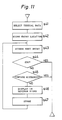
- the operator selects the textual data belonging to the highest level of hierarchy within the textual data on which to perform text manipulation. The selection is accomplished by moving the cursor to the line of the desired textual data using a cursor key and then depressing the "select" key.
- access is made to the entry 108 of the management table 107 corresponding to the selected textual data, and the location of the entry 108 is stored.
- access is made to the entry 108 next to the last accessed entry 108.
- step s44 it is checked whether any data is stored in the accessed entry 108; if data is stored there, the process proceeds to step s45, and if not, it is determined that the end of the textual data is reached, and the processing for determining the range is terminated.
- step s45 it is checked whether the value of the hierarchy field 111 of the entry 108 accessed at step s43 is larger than the value of the hierarchy field 111 of the entry 108 whose location was stored at step s42; if the value is larger, the process proceeds to step s46, and if not, the processing is terminated.
- step s46 the textual data corresponding to the accessed entry 108 is displayed in reverse video.
- step s47 the location of the accessed entry 108 is stored, and the process returns to step s43.
- deletion or other text manipulation is performed on the range of text determined by the entries 108 whose locations have been stored during the processing of Fig.11.
- the kind of text manipulation may be specified either before or after determining the range of text for processing.
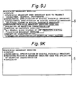
- Fig.9J shows the display when the major item "Prototype " has been specified for processing. As shown, the selected major item "Prototype " and the textual data directly or indirectly subordinate to the major item are displayed in reverse video.
- the display can be switched between the display of all textual data and the display of the major items only.
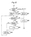
- the processing for switching the display will now be described with reference to Fig.12.
- a flag not shown is referenced to check whether the current display mode is the full text display mode or the major item only display mode (step s51). If it is determined as the full text display mode, the process proceeds to step s52; if not, the process proceeds to step s57.
- the flag is updated to switch the display mode while the management table 107 is searched to retrieve the title entry 108.
- step s54 If the retrieval has been made successfully, the process proceeds to step s54; if not, the process proceeds to the display step (step s58) since it means that there are no further entries 108 to be retrieved.
- step s54 it is checked whether the value of the hierarchy field 111 of the retrieved entry 108 is equal to "0001" which represents the hierarchy of the major item, and if the values match, the process proceeds to step s55; if not, the process proceeds to step s56.
- step s55 the location of the retrieved entry 108 is stored.
- step s56 the entry 108 next to the retrieved entry 108 is retrieved, after which the process returns to step s53.
- step s57 the flag is updated to switch the display mode while storing the locations of all entries 108 of the management table 107, after which the process proceeds to the display step (step s58).
- step s58 the textual data is displayed in accordance with the stored entry locations.
- Fig.9K shows an example of display in the major item only display mode.
- the major item only display mode allows the operator to grasp the entire text construction on a display of a limited size.
- only the major item only display mode is provided as a display mode for displaying part of textual data, but by making suitable modifications to the processing shown in Fig.12, it is possible to provide various selective displays such as selective display of medium items subordinate to a certain major item, display of major and medium items only, etc.
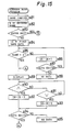
- the calendar program works first to read the current year and date (e.g., May 1, 1990) from the RTC 11 and substitutes the year, month, and day for variables YY, MM, and DD, respectively (step s61).
- the value representing the day of the week of January 1st of the year YY is read out by referencing the table in the ROM 9, and the value ("0" for Sunday, "1" for Monday, and so on) is substituted for a variable W (since January 1st of 1990 is Monday, "1" is substituted for the variable W).
- step s63 it is checked whether the year YY is a leap year; if it is a leap year, the process proceeds to step s65, and if not, the process proceeds to step s64.
- step s65 it is checked whether the month MM is a month (MM ⁇ 2) requiring special processing because of a leap year; if the month MM is a month requiring such processing, the process proceeds to step s66, and if not, the process proceeds to step s64.
- step s64 a value to calculate the day of the week of the 1st day of the month MM is fetched from the table in the ROM 9 for a non-leap year.
- this table contains a value "1" which is the result of subtracting 1 from the remainder 2 obtained by dividing 121 by 7, since May 1st is the 121st day from January 1st.
- a value to calculate the day of the week of the 1st day of the month MM is fetched from the table in the ROM 9 for a leap year.
- the number of days in the month MM is fetched from the table in the ROM 9 (for example, "31" is fetched for the month of May).
- step s70 the calendar for the month MM of the year YY is displayed (step s70), and the day DD on the displayed calendar is shown by blinking (step s71).
- the calendar program works to display the calendar for the previous month or the next month, as described below with reference to the flowchart of Fig.14.
- steps S72 and S73 it is checked whether a cursor key is depressed or not; if it is decided that the cursor UP key has been depressed, the process proceeds to step s74, and if it is decided that the cursor DOWN key has been depressed, the process proceeds to step s75.
- steps S74 and S75 it is decided whether the current calendar is for the first month (January) of the year or whether it is for the last month (December) of the year, and in accordance with the result of the decision, the process proceeds to one of the steps S76-S79.
- steps S76-S79 appropriate values are substituted for the variable YY and/or MM. "1" is substituted for the variable DD (step s80), and the process returns to step s62 of Fig.13.
- the address book program works first to display the message "Name?" on the LCD 5, prompting the operator to enter the name which is used as the keyword for data search (step s81).
- the entered name is substituted for the variable A.
- the operator depresses a cursor key if a search is to be performed by the entered name, and depresses the "enter” key if new address book data for the entered name is to be created.
- address book data consisting of the name, address, and telephone number is stored as a set of data.
- the location of the address book data at the top of the address book memory area 101 is stored in IX register.
- step s87 it is checked whether address book data exists at the location indicated by the IX register; if no data exists, a message is displayed to the effect that the specified name is not stored (step s88), and if data exits, the name match is checked again at step s85.
- step s89 After the address book data is displayed at step s89, when a cursor key is operated, the address book data stored before or after the current data is displayed.
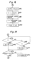
- steps S90 and S91 of Fig.15 it is checked whether a cursor key is depressed; if it is decided that the cursor UP key has been depressed, the process proceeds to step s92, and if it is decided that the cursor DOWN key has been depressed, the process proceeds to step s93.
- step s92 "1" is subtracted from the IX register to store the location of the preceding address book data in the IX register.
- step s93 "1" is added to the IX register to store the location of the next address book data in the IX register.
- step s94 it is checked whether address book data exists at the location indicated by the IX register; if data exists, the process returns to the display step (step s89), and if no data exists, a message indicating no data is displayed (step s95).
- step s96 the operator is prompted to enter the address.
- the entered address is substituted for the variable B (step s97).
- step s98 the operator is prompted to enter the telephone number.
- the entered telephone number is substituted for the variable C (step s99).
- step s100 data substituted for the variables A, B, and C is stored after the last address book data stored in the address book memory area in the RAM 10, to complete the registration of the address book data for one person.
- textual data stored in the data exchange memory area 110 by the text creation program can be loaded as address book data using the "call" key.
- the schedule program works first to read the current year and date from the RTC 11 and substitutes the year, month, and day for the variables YY, MM, and DD (step s101).
- the schedule memory area (schedule list) 102 in the RAM 10 the previously mentioned schedule data is stored in sequence by date.
- the location of the schedule data stored at the top of the schedule memory area 102 is stored in the IX register.
- step s104 addition is performed so that the location of the next schedule data in the schedule memory area 102 is stored into the IX register.
- step s105 it is checked whether schedule data exists at the location indicated by the IX register; if schedule data exists, the process returns to step s103, and if not, a message indicating no schedule is displayed at step s112.
- the schedule data nearest to the current date is retrieved from the future schedule including that for the current year.
- Steps S106 to S108 provide a similar loop structure to that of steps S103 to S105 and are used to make judgement about the month of the schedule.
- Steps S109 to S111 also provide a similar loop structure to that of steps S103 to S105 and are used to make judgement about the day of the schedule.
- the retrieved schedule data (including date and schedule item) is displayed.
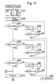
- step s113 After the schedule data is displayed at step s113, when a cursor key is operated, the schedule data stored before or after the current schedule data is displayed in accordance with the process shown in Fig.18.
- steps S114 and S115 of Fig.18 it is checked whether a cursor key is depressed or not; if it is decided that the cursor UP key has been depressed, the process proceeds to step s116, and if it is decided that the cursor DOWN key is depressed, the process proceeds to step s117.
- step s116 "1" is subtracted from the IX register, to store the memory location of the preceding schedule data into the IX register.
- step s117 "1" is added to the IX register, to store the location of the next schedule data into the IX register.
- step s118 it is checked whether schedule data exists at the location indicated by the IX register; if schedule data exists, the process returns to the display step (step s113), and if no schedule exists, a message indicating no schedule is displayed (step s119).
- step s121 the operator is prompted to enter the date of schedule.
- the entered date is substituted for the variable A (step s122).
- step s123 the operator is prompted to enter the schedule item.
- the entered schedule item is substituted for the variable B (step s124).
- the entered schedule date is compared with the schedule dates stored in the schedule memory area 102 to determine the location in the schedule memory area 102 at which to store the entered schedule data, and the schedule after that location is shifted so as to secure an area in which to store the schedule data entered at that location, thus storing the entered schedule data into the memory area thus secured.
- textual data stored in the data exchange memory 110 by the text creation program can also be read into the schedule using the "call" key.
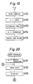
- the memo program works first to load into the IX register the location of the entry storing the location and character number of the last memo data stored in the table 104 that manages the start position in the memo data memory area 103 and the number of characters of each memo data stored in the memory area 103 in the RAM 10 (step s131).
- the desired memo data is read out of the memo data memory area 103 (step s132), and the thus read-out data is displayed (step s133).
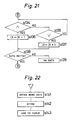
- step s133 After the memo data is displayed in step s133, when a cursor key is operated, the memo data stored before or after the current memo data is displayed in accordance with the process shown in Fig.21.
- steps S134 and S135 of Fig.21 it is checked whether a cursor key is depressed or not; if it is decided that the cursor UP key has been depressed, the process proceeds to step s136, and if it is decided that the cursor DOWN key is depressed, the process proceeds to step s137.
- step s136 "1" is subtracted from the IX register, to load into the IX register the location of the entry of the table 104 storing the start position and the number of characters of the preceding memo data.
- step s137 "1" is added to the IX register, to load into the IX register the location of the entry of the table 104 storing the start position and the number of characters of the next memo data.
- step s138 it is checked whether memo data exists in the table entry indicated by the IX register; if data exists in the table entry, the process returns to the memo data read step (step s132), and if no data exists, a message indicating no data is displayed (step s139).
- step s141 When a character key or a numeric key is operated during the operation of the memo program, the process jumps to step s141 of Fig.22 to enter the memo data input mode.
- step s141 memo data is entered, followed by the depression of the "enter" key to store the entered memo data after the last memo data stored in the memo data memory area 103 (step s142).
- step s143 the entry storing the start position and the number of characters of the memo data stored at step s142 is added to the table 104.
- textual data stored in the data exchange memory area 110 by the text creation program can also be read as memo data using the "call" key. Since the data exchange memory area 110 stores textual data with delimiters, the memo program can display the loaded textual data on the LCD 5 using the delimiters to provide carriage returns at appropriate points.
- the application program in the memory card 7 of Fig.3 is an English dictionary program with a spelling check function. This program starts by displaying an "ENTER WORD" prompt on the LCD 5, as shown in Fig.23A. After a word is entered, as shown in Fig.23B, when the "CORRECT" key 701 on the memory card is depressed, the dictionary contained in the memory card 7 is searched for the entered word. When the word is found in the dictionary, the message "IT'S CORRECT" is displayed, as shown in Fig.23C, notifying the operator that the entered word is spelled correctly.
- the "HYPHEN” key 705 is a key used to display the entered word divided into syllables, while the "?" key 706 is used to enter the character "?” in place of an unknown character in the word being entered. Since the comparison for a character match with the words in the dictionary is skipped on the character positions of "?” in the entered word during the search for the entered word, using the character "?” makes it possible to search for a word the spelling of which the operator is unsure of.
- Fig.24 shows an external plan view of another embodiment of the invention.
- This embodiment is a small electronic apparatus generally known as an "electronic organizer".
- the construction of this embodiment is essentially the same as that of the small electronic apparatus 1 of the foregoing embodiment, but since the construction is partially different, the construction of this embodiment will be described in full. It should also be noted that the reference numerals are essentially the same between the two embodiments but partially different.
- the electronic organizer 1a shown in Fig.24 consists of a main body 2 and a main body cover 3.
- Fig.24 shows the electronic organizer 1a with the main body cover 3 opened.
- the main body 2 is provided with a keyboard 4 having an "ON" key 41 to turn on power and an “OFF” key 42 to turn off power.
- a mode selector section 43 includes keys for switching the modes or selecting the application program to be executed.
- a data input section 44 comprises alphabetic keys including an [S] key 441, numeric keys including an [1] key 446 and a [4] key 447, an [ENTER] key 440 to determine the entry of data, and other keys.
- a [H] key 442 functions as a [HELP] key when operated immediately after the [SHIFT] key 48.
- a [U] key 443 functions as a [SEEK] key when operated immediately after the [SHIFT] key 48.
- a [Q] key 444 functions as an [EDIT] key when operated immediately after the [SHIFT] key 48.
- the key is referred to using the name of its second function.
- the [H] key 442 is operated immediately after the [SHIFT] key 48
- a liquid crystal display (LCD) 5 capable of displaying a plurality of lines and a transparent keyboard 6.
- LCD liquid crystal display
- Other types of display device having a low power dissipation may be used instead of the LCD 5.
- a memory card containing an application program for expansion of the function of the electronic organizer 1a is inserted into position through a slot (not shown) near the hinge on the back of the main body cover 3 in such a way that the front face of the memory card can be seen through the transparent keyboard 6.
- the transparent keyboard 6 is used when executing the application program contained in the memory card.
- Fig.25 shows the hardware configuration of the electronic organizer 1a.
- a control section 8 for controlling the electronic organizer 1a contains a CPU 81 and a gate array 82.
- the LCD 5 shown in Fig.24 is connected to the control section 8 via a decoder 51, a bit map memory 52, a common driver 53, and a segment driver 54.
- the data to be displayed on the LCD 5 is supplied from the control section 8 to the decoder 51.
- the decoder 51 decodes the data and writes it into the bit map memory 52.
- the bit map memory 52 is a memory in which one bit is assigned to every dot of the LCD 5, the bits corresponding to the dots to illuminate being set to "1" and the other bits being set to "0".
- the common driver 53 and the segment driver 54 are used to display characters, graphics, etc. on the LCD 5 according to the contents stored in the bit map memory 52.
- the reference numeral 45 shows a key matrix for detecting key entries from the keyboard 4, while the reference numeral 65 indicates a key matrix for detecting key entries from the transparent keyboard 6.
- a real time clock (RTC) 11 Also connected to the control section 8 are a real time clock (RTC) 11, an expansion terminal 12 for connecting an electronic apparatus such as a printer, a personal computer, or an electronic organizer of the same type as that of this embodiment, and an expansion terminal 13 dedicated for a memory card.
- RTC real time clock
- an expansion terminal 12 for connecting an electronic apparatus such as a printer, a personal computer, or an electronic organizer of the same type as that of this embodiment
- an expansion terminal 13 dedicated for a memory card.
- a male connector 14 Connected to the expansion terminal 13 are a male connector 14 to which the female connector 73 of the memory card 7 is connected and a detector 15 for detecting the connection of the male connector 14 to the female connector 73 of the memory card 7.
- the ROM 9 stores a basic program for performing basic functions including handling of data input from the keyboard 4 and the transparent keyboard 6 and displaying on the LCD 5; a plurality of application programs for performing a calendar display function, a telephone book function, a text creation function, a schedule management function, a memo function, a business card file function, etc.; and a plurality of tables having fixed contents used in application programs for calendar display, etc.
- the RAM 10 is used to store variable information needed by the application programs stored in the ROM 9, data created by using the application programs, etc.
- the RAM 10 has a telephone book memory area 101, a schedule memory area 102, a memo data memory area 103, a table 104 for managing the information relating to the memo data stored in the memo data memory area 103, a mode memory area 105 for storing the various modes, a textual data memory area 106, a management table 107 for managing hierarchical relationships, etc. of the textual data stored in the text memory area 106, a business card memory area 109, and a data exchange memory area 110 for exchanging data between the application programs.
- the RAM 10 also has areas for storing various variables, pointers, and flags. Furthermore, the RAM 10 has a temporary memory area 111 used for data search.
- step a1 When the operator selects a mode at step a1, an application program corresponding to the selected mode is started, and data under the control of the selected mode is loaded (step a2). At step a3, the loaded data is displayed on the LCD 5. At step a4, it is checked whether execution of data search is specified. In this embodiment, the operator depresses the [SHIFT] key 48 and the [SEEK] key 443 successively to specify execution of data search. When data search is not specified, the process proceeds to step a5 to perform processing such as switching of display data, input of new data, etc.
- step a4 When execution of data search is specified at step a4, the data search mode is entered, the process proceeding to step a6.
- step a6 the first character string in the displayed data separated by a blank is automatically specified as the search character string which serves as the keyword for data search, the specified search character string being displayed in reverse video on the LCD 5.
- step a7 it is checked whether an instruction to move the cursor is issued. If an instruction to move the cursor is issued, the process proceeds to step a8 to change the search character string.
- the processing at step a8 is different according to the mode of cursor movement.
- One mode is when one of the cursor keys 45 is depressed, in which case another character string separated by a blank is specified as a new search character string, in accordance with the direction indicated by the depressed cursor key 45.
- the other mode is when one of the arrow keys 49 and one of the cursor keys 45 are depressed simultaneously, in which case the character in the direction indicated by the depressed cursor key 45 is added to the current search character string.
- step a9 When no instruction for cursor movement is issued at step a7, the process proceeds to step a9 in which it is checked whether the [ENTER] key 440 is depressed. If the [ENTER] key 440 is depressed, the process proceeds to step a10, an1 if not, the process returns to step a7. At step a10, the specified search character string is stored into the temporary memory area 111. In the meantime, a message is displayed on the LCD 5, prompting the operator to select the mode under which data search is to be performed.
- step a11 When the mode is selected at step a11, the process proceeds to step a12 in which the data containing the search character string is retrieved from the data under the control of the selected mode. At step a13, the retrieved data is displayed. Thereafter, the process returns to step a7.
- this embodiment permits data retrieval in such a manner that, for example, a search character string is designated in a certain mode, a search is performed in another mode using that search character string, a search character string is designated in that other mode, and a search is performed in still another mode using the latter search character string.
- the processing after entering the search mode is performed successively as a series of process specifically reserved for data retrieval, but the following modification can be considered.
- the search character string designated in a certain mode is stored in the temporary memory area 111. Thereafter, regardless of the designation of the search character string, when another mode is entered and execution of data retrieval is specified, the operator is prompted determines whether to fetch the search character string from the temporary memory area 111 or to enter a new search character string from the keyboard 4.
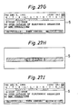
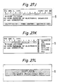
- Figs.27A to 27N show examples of displays for data search operation according to this embodiment.
- Fig.27A shows that data is displayed in the telephone book mode.
- the [SHIFT] key 48 and the [SEEK] key 443 are depressed for execution of data search, the first character string "HAMILTON" in the displayed data is automatically designated as the search character string and is displayed in reverse video, as shown in Fig.27B.
- the cursor DOWN key 45 is depressed four times, the search character string is changed to the character string "ABC" four lines below (Fig.27C).
- the search character string is extended to the right as shown in Fig.27D.
- the search character string is stored into the temporary memory area 111, while a list of mode names is displayed on the rightmost side of the screen, as shown in Fig.27E.
- the operator selects the schedule mode by depressing the [1] key 446.
- the mode is selected, a search beings and a message indicating that the search is being performed is displayed during the search operation, as shown in Fig.27F.
- the retrieved data is displayed on the LCD 5, as shown in Fig.27G.
- Fig.27H shows the display when applicable data was not found as a result of the search carried out by such a key operation.
- the operator changes the search character string in the schedule mode and uses the search character string for data search in the memo mode.
- Fig.27M shows the result of the data search in the memo mode.
- Fig.27N shows the display after the [C ⁇ CE] key 47 has been depressed in the situation of Fig.27M.
- Fig.28(a) shows a piece of company data.
- the company data comprises a company code 301 an d a company name data 302.
- the company code 301 is fixed-length data, but since the company name data 302 is variable-length data, individual pieces of company data are separated from each other by a delimiter. There are as many pieces of company data as the number of companies stored.
- new company data is created in the business card data memory area 109.
- the company code 301 is automatically attached by the business card file program.
- Fig.28(b) shows a piece of departmental data.
- the departmental data comprises a company code 301, a departmental code 304, a departmental name 305, a departmental telephone number 306, a departmental FAX number 307, and a departmental address 308.
- the departmental data is related to the company data by the company code 301. There are as many pieces of departmental data as the number of companies stored.
- new department data is created in the business card data area 109.
- the departmental code 304 is automatically attached by the business card file program.
- Fig.28(c) shows personal data for one person.
- the personal data comprises a company code 301, a departmental code 304, a person's name 309, a person's telephone number 310, and a person's official position 311.
- the personal data is related to the company data by the company code 301 and to the departmental data by the departmental code 304.
- the company data and the departmental data are stored separately from the personal data, the effect of which is that it not only takes less space in the memory area than when the company name, departmental name, etc. are duplicated among a plurality of personal data, but also facilitates data search hereinafter described. It will be appreciated that it is also possible to store personal data with company data and departmental data included therein, instead of storing the business card data as mentioned above.
- step b1 a message prompting the operator to enter a company name is displayed (step b1).
- step b3 it is checked whether the data entered at step b2 consists of one character; if it consists of one character, the process proceeds to step b4, and if it consists of more than one character, the process proceeds to step b14.
- step b4 company names beginning with the character entered at step b2 is read from the business card data memory area 109 for display as a list.
- the display also includes an option for entering a new company name not included in the list.
- step b6 it is checked at step b6 whether the key entry made at step b5 is for selecting an input of a new company name; if it is for inputting a new company name, the process proceeds to step b14, and if not, that is, if a company name is selected from the displayed list, the process proceeds to step b7.
- step b7 the selected company name is displayed as the entered company name.
- processing of a keyed-in company name is performed.
- step b8 the business card memory area 109 is examined to check whether the departmental data corresponding to the selected company name is registered. If the departmental data is registered, the process proceeds to step b9 to display a list of the registered departmental data. The display also includes an option for entering new departmental data not included in the list. On the other hand, if no departmental data is registered, the process proceeds to step b15.
- step b11 After displaying the list at step b9, it is checked at step b11 whether the key entry made at step b10 is for selecting an input of new departmental data; if new departmental data input is selected, the process proceeds to step b15, and if not, that is, if departmental data is selected from the displayed list of departmental data, the process proceeds to step b12.
- step b12 the selected departmental data is displayed as the entered departmental data.
- step b15 processing of keyed-in departmental data is performed.
- new departmental data as shown in Fig.28(b) is created.
- step b13 input processing of personal data is performed. With the above procedure, input of business card data for one person is completed.
- a list of company names already stored in other business card data is displayed when entering a company name, and thus, the company name to be entered can be selected from the displayed list. Therefore, when the company name to be entered is a one already registered, the company name can be entered by a very simple operation. For departmental data also, since a list of registered data is displayed from which the desired departmental name can be selected, entering departmental data is also very simple, as in the case of entering a company name.
- a list of registered company names is displayed by depressing a specific function key.
- the function to display a list of registered data and select desired data from the displayed list can also be applied to other programs requiring data input.
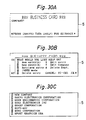
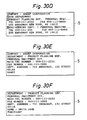
- Figs.30A to 30J show examples of displays during execution of the business card file program.
- Fig.30A shows the display when the business card file program is started. As shown, the display is prompting the operator to enter a company name.
- Fig.30A or Fig.30B With the display of Fig.30A or Fig.30B on the screen, when the [S] key 441 and the [ENTER] key 440 are depressed, a list of registered company names beginning with the character "S" is displayed as shown in Fig.30C.
- a company name is selected by depressing the [4] key 447, the selected company name is displayed on the company name field as shown in Fig.30D, with a list of departmental data registered under the company name being displayed.
- departmental data is selected by depressing the [1] key 446, the selected departmental data is displayed, as shown in Fig.30E, with a message prompting the operator to enter a name.
- Fig.30F shows a display after the name has been entered. A message is displayed prompting the operator to enter the person's position.
- Fig.30G shows a display after the position has been entered. A message is displayed prompting the operator to enter the telephone number.
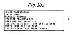
- a message appears indicating that the entered business card data is being saved, as shown in Fig.30I, after which the entered business card data is displayed in the prescribed format as shown in Fig.30J.
Landscapes
- Engineering & Computer Science (AREA)
- Theoretical Computer Science (AREA)
- Physics & Mathematics (AREA)
- General Engineering & Computer Science (AREA)
- General Physics & Mathematics (AREA)
- Audiology, Speech & Language Pathology (AREA)
- Computational Linguistics (AREA)
- General Health & Medical Sciences (AREA)
- Health & Medical Sciences (AREA)
- Artificial Intelligence (AREA)
- Computing Systems (AREA)
- Computer Hardware Design (AREA)
- Calculators And Similar Devices (AREA)
- Information Retrieval, Db Structures And Fs Structures Therefor (AREA)
Applications Claiming Priority (9)
| Application Number | Priority Date | Filing Date | Title |
|---|---|---|---|
| JP12178990 | 1990-05-11 | ||
| JP2121789A JPH0418665A (ja) | 1990-05-11 | 1990-05-11 | 小型電子機器 |
| JP121789/90 | 1990-05-11 | ||
| JP14503790 | 1990-06-01 | ||
| JP2145037A JPH0437955A (ja) | 1990-06-01 | 1990-06-01 | 小型電子機器 |
| JP2145038A JPH0833794B2 (ja) | 1990-06-01 | 1990-06-01 | 小型電子機器 |
| JP145037/90 | 1990-06-01 | ||
| JP14503890 | 1990-06-01 | ||
| JP145038/90 | 1990-06-01 |
Publications (3)
| Publication Number | Publication Date |
|---|---|
| EP0461400A2 true EP0461400A2 (de) | 1991-12-18 |
| EP0461400A3 EP0461400A3 (en) | 1993-12-15 |
| EP0461400B1 EP0461400B1 (de) | 2000-10-04 |
Family
ID=27314322
Family Applications (1)
| Application Number | Title | Priority Date | Filing Date |
|---|---|---|---|
| EP91107630A Expired - Lifetime EP0461400B1 (de) | 1990-05-11 | 1991-05-10 | Textverarbeitungsgerät |
Country Status (3)
| Country | Link |
|---|---|
| US (1) | US5331555A (de) |
| EP (1) | EP0461400B1 (de) |
| DE (1) | DE69132434T2 (de) |
Cited By (3)
| Publication number | Priority date | Publication date | Assignee | Title |
|---|---|---|---|---|
| EP0597499A3 (en) * | 1992-11-13 | 1994-07-06 | Sharp Kk | Electronic note book. |
| EP0597794A3 (de) * | 1992-11-13 | 1994-10-12 | Ibm | Verfahren in einem Datenverarbeitungssystem zur graphischen Wechselwirkung zwischen Daten und Anwendungen. |
| EP1024440A3 (de) * | 1999-01-29 | 2002-02-06 | Hewlett-Packard Company, A Delaware Corporation | Verfahren zum Wiederauffinden von Daten |
Families Citing this family (125)
| Publication number | Priority date | Publication date | Assignee | Title |
|---|---|---|---|---|
| US5307263A (en) | 1992-11-17 | 1994-04-26 | Raya Systems, Inc. | Modular microprocessor-based health monitoring system |
| US8626521B2 (en) | 1997-11-21 | 2014-01-07 | Robert Bosch Healthcare Systems, Inc. | Public health surveillance system |
| US5832448A (en) | 1996-10-16 | 1998-11-03 | Health Hero Network | Multiple patient monitoring system for proactive health management |
| US7624028B1 (en) | 1992-11-17 | 2009-11-24 | Health Hero Network, Inc. | Remote health monitoring and maintenance system |
| US20010011224A1 (en) | 1995-06-07 | 2001-08-02 | Stephen James Brown | Modular microprocessor-based health monitoring system |
| US9215979B2 (en) * | 1992-11-17 | 2015-12-22 | Robert Bosch Healthcare Systems, Inc. | Multi-user remote health monitoring system |
| WO2001037174A1 (en) | 1992-11-17 | 2001-05-25 | Health Hero Network, Inc. | Method and system for improving adherence with a diet program or other medical regimen |
| US6968375B1 (en) * | 1997-03-28 | 2005-11-22 | Health Hero Network, Inc. | Networked system for interactive communication and remote monitoring of individuals |
| US5586317A (en) * | 1993-07-30 | 1996-12-17 | Apple Computer, Inc. | Method and apparatus for implementing I/O in a frame-based computer system |
| US5822720A (en) | 1994-02-16 | 1998-10-13 | Sentius Corporation | System amd method for linking streams of multimedia data for reference material for display |
| JP3243365B2 (ja) * | 1994-04-19 | 2002-01-07 | シャープ株式会社 | キー入力装置 |
| US8015033B2 (en) | 1994-04-26 | 2011-09-06 | Health Hero Network, Inc. | Treatment regimen compliance and efficacy with feedback |
| US6684188B1 (en) * | 1996-02-02 | 2004-01-27 | Geoffrey C Mitchell | Method for production of medical records and other technical documents |
| US6032119A (en) | 1997-01-16 | 2000-02-29 | Health Hero Network, Inc. | Personalized display of health information |
| US20050033132A1 (en) * | 1997-03-04 | 2005-02-10 | Shults Mark C. | Analyte measuring device |
| US7192450B2 (en) | 2003-05-21 | 2007-03-20 | Dexcom, Inc. | Porous membranes for use with implantable devices |
| US7899511B2 (en) | 2004-07-13 | 2011-03-01 | Dexcom, Inc. | Low oxygen in vivo analyte sensor |
| US9155496B2 (en) | 1997-03-04 | 2015-10-13 | Dexcom, Inc. | Low oxygen in vivo analyte sensor |
| US8527026B2 (en) | 1997-03-04 | 2013-09-03 | Dexcom, Inc. | Device and method for determining analyte levels |
| US6001067A (en) | 1997-03-04 | 1999-12-14 | Shults; Mark C. | Device and method for determining analyte levels |
| US6862465B2 (en) | 1997-03-04 | 2005-03-01 | Dexcom, Inc. | Device and method for determining analyte levels |
| US8480580B2 (en) | 1998-04-30 | 2013-07-09 | Abbott Diabetes Care Inc. | Analyte monitoring device and methods of use |
| US6949816B2 (en) | 2003-04-21 | 2005-09-27 | Motorola, Inc. | Semiconductor component having first surface area for electrically coupling to a semiconductor chip and second surface area for electrically coupling to a substrate, and method of manufacturing same |
| US6175752B1 (en) | 1998-04-30 | 2001-01-16 | Therasense, Inc. | Analyte monitoring device and methods of use |
| US8465425B2 (en) | 1998-04-30 | 2013-06-18 | Abbott Diabetes Care Inc. | Analyte monitoring device and methods of use |
| US8688188B2 (en) | 1998-04-30 | 2014-04-01 | Abbott Diabetes Care Inc. | Analyte monitoring device and methods of use |
| US8346337B2 (en) | 1998-04-30 | 2013-01-01 | Abbott Diabetes Care Inc. | Analyte monitoring device and methods of use |
| US9066695B2 (en) | 1998-04-30 | 2015-06-30 | Abbott Diabetes Care Inc. | Analyte monitoring device and methods of use |
| US8974386B2 (en) | 1998-04-30 | 2015-03-10 | Abbott Diabetes Care Inc. | Analyte monitoring device and methods of use |
| US7496854B2 (en) * | 1998-11-10 | 2009-02-24 | Arendi Holding Limited | Method, system and computer readable medium for addressing handling from a computer program |
| NO984066L (no) * | 1998-09-03 | 2000-03-06 | Arendi As | Funksjonsknapp for datamaskin |
| US7272604B1 (en) * | 1999-09-03 | 2007-09-18 | Atle Hedloy | Method, system and computer readable medium for addressing handling from an operating system |
| EP0992953A3 (de) * | 1998-10-08 | 2004-06-02 | Canon Kabushiki Kaisha | Schnittstellensystem für benutzerprogammierbare Chipkarten |
| JP4098435B2 (ja) * | 1999-03-12 | 2008-06-11 | 富士通株式会社 | 情報管理装置及びデータ生成方法並びに情報管理プログラムを格納したコンピュータ読取り可能な記録媒体 |
| US6874683B2 (en) * | 1999-10-08 | 2005-04-05 | Canon Kabushiki Kaisha | User programmable smart card interface system for an image album |
| US6871782B2 (en) * | 1999-10-08 | 2005-03-29 | Canon Kabushiki Kaisha | User programmable smart card interface system having an arbitrary mapping |
| US6980870B1 (en) * | 2000-08-28 | 2005-12-27 | Mok Mimi T | Method and apparatus for optimizing, managing and scheduling personal relationships |
| US6560471B1 (en) | 2001-01-02 | 2003-05-06 | Therasense, Inc. | Analyte monitoring device and methods of use |
| US20030032874A1 (en) | 2001-07-27 | 2003-02-13 | Dexcom, Inc. | Sensor head for use with implantable devices |
| US6702857B2 (en) | 2001-07-27 | 2004-03-09 | Dexcom, Inc. | Membrane for use with implantable devices |
| US6885314B2 (en) | 2001-08-16 | 2005-04-26 | Dror Levin | Hand-held input device particularly useful as a keyboard |
| US7130861B2 (en) | 2001-08-16 | 2006-10-31 | Sentius International Corporation | Automated creation and delivery of database content |
| US9247901B2 (en) | 2003-08-22 | 2016-02-02 | Dexcom, Inc. | Systems and methods for replacing signal artifacts in a glucose sensor data stream |
| US9282925B2 (en) | 2002-02-12 | 2016-03-15 | Dexcom, Inc. | Systems and methods for replacing signal artifacts in a glucose sensor data stream |
| US7828728B2 (en) | 2003-07-25 | 2010-11-09 | Dexcom, Inc. | Analyte sensor |
| US7613491B2 (en) | 2002-05-22 | 2009-11-03 | Dexcom, Inc. | Silicone based membranes for use in implantable glucose sensors |
| US8260393B2 (en) | 2003-07-25 | 2012-09-04 | Dexcom, Inc. | Systems and methods for replacing signal data artifacts in a glucose sensor data stream |
| US8010174B2 (en) | 2003-08-22 | 2011-08-30 | Dexcom, Inc. | Systems and methods for replacing signal artifacts in a glucose sensor data stream |
| US7226978B2 (en) | 2002-05-22 | 2007-06-05 | Dexcom, Inc. | Techniques to improve polyurethane membranes for implantable glucose sensors |
| US7134999B2 (en) | 2003-04-04 | 2006-11-14 | Dexcom, Inc. | Optimized sensor geometry for an implantable glucose sensor |
| US7875293B2 (en) * | 2003-05-21 | 2011-01-25 | Dexcom, Inc. | Biointerface membranes incorporating bioactive agents |
| US8423113B2 (en) | 2003-07-25 | 2013-04-16 | Dexcom, Inc. | Systems and methods for processing sensor data |
| JP4708342B2 (ja) | 2003-07-25 | 2011-06-22 | デックスコム・インコーポレーテッド | 埋設可能な装置に用いる酸素増大膜システム |
| US7761130B2 (en) | 2003-07-25 | 2010-07-20 | Dexcom, Inc. | Dual electrode system for a continuous analyte sensor |
| US7519408B2 (en) | 2003-11-19 | 2009-04-14 | Dexcom, Inc. | Integrated receiver for continuous analyte sensor |
| US8275437B2 (en) | 2003-08-01 | 2012-09-25 | Dexcom, Inc. | Transcutaneous analyte sensor |
| US7778680B2 (en) | 2003-08-01 | 2010-08-17 | Dexcom, Inc. | System and methods for processing analyte sensor data |
| US8626257B2 (en) | 2003-08-01 | 2014-01-07 | Dexcom, Inc. | Analyte sensor |
| US7925321B2 (en) | 2003-08-01 | 2011-04-12 | Dexcom, Inc. | System and methods for processing analyte sensor data |
| US7494465B2 (en) | 2004-07-13 | 2009-02-24 | Dexcom, Inc. | Transcutaneous analyte sensor |
| US8886273B2 (en) | 2003-08-01 | 2014-11-11 | Dexcom, Inc. | Analyte sensor |
| US7591801B2 (en) | 2004-02-26 | 2009-09-22 | Dexcom, Inc. | Integrated delivery device for continuous glucose sensor |
| US8369919B2 (en) | 2003-08-01 | 2013-02-05 | Dexcom, Inc. | Systems and methods for processing sensor data |
| US8160669B2 (en) | 2003-08-01 | 2012-04-17 | Dexcom, Inc. | Transcutaneous analyte sensor |
| US20190357827A1 (en) | 2003-08-01 | 2019-11-28 | Dexcom, Inc. | Analyte sensor |
| US7774145B2 (en) | 2003-08-01 | 2010-08-10 | Dexcom, Inc. | Transcutaneous analyte sensor |
| US8761856B2 (en) | 2003-08-01 | 2014-06-24 | Dexcom, Inc. | System and methods for processing analyte sensor data |
| US8845536B2 (en) | 2003-08-01 | 2014-09-30 | Dexcom, Inc. | Transcutaneous analyte sensor |
| US20100168542A1 (en) | 2003-08-01 | 2010-07-01 | Dexcom, Inc. | System and methods for processing analyte sensor data |
| US9135402B2 (en) * | 2007-12-17 | 2015-09-15 | Dexcom, Inc. | Systems and methods for processing sensor data |
| US7920906B2 (en) | 2005-03-10 | 2011-04-05 | Dexcom, Inc. | System and methods for processing analyte sensor data for sensor calibration |
| US8233959B2 (en) | 2003-08-22 | 2012-07-31 | Dexcom, Inc. | Systems and methods for processing analyte sensor data |
| US20140121989A1 (en) | 2003-08-22 | 2014-05-01 | Dexcom, Inc. | Systems and methods for processing analyte sensor data |
| US9247900B2 (en) | 2004-07-13 | 2016-02-02 | Dexcom, Inc. | Analyte sensor |
| US8774886B2 (en) | 2006-10-04 | 2014-07-08 | Dexcom, Inc. | Analyte sensor |
| US8287453B2 (en) | 2003-12-05 | 2012-10-16 | Dexcom, Inc. | Analyte sensor |
| EP2239567B1 (de) | 2003-12-05 | 2015-09-02 | DexCom, Inc. | Kalibrierverfahren für einen kontinuierlichen Analytsensor |
| US8423114B2 (en) | 2006-10-04 | 2013-04-16 | Dexcom, Inc. | Dual electrode system for a continuous analyte sensor |
| US8364231B2 (en) | 2006-10-04 | 2013-01-29 | Dexcom, Inc. | Analyte sensor |
| US8425416B2 (en) | 2006-10-04 | 2013-04-23 | Dexcom, Inc. | Analyte sensor |
| US8364230B2 (en) | 2006-10-04 | 2013-01-29 | Dexcom, Inc. | Analyte sensor |
| US11633133B2 (en) | 2003-12-05 | 2023-04-25 | Dexcom, Inc. | Dual electrode system for a continuous analyte sensor |
| US8425417B2 (en) | 2003-12-05 | 2013-04-23 | Dexcom, Inc. | Integrated device for continuous in vivo analyte detection and simultaneous control of an infusion device |
| EP2316331B1 (de) | 2003-12-09 | 2016-06-29 | Dexcom, Inc. | Signalverarbeitung in einem durchgehenden Analytsensor |
| US8808228B2 (en) | 2004-02-26 | 2014-08-19 | Dexcom, Inc. | Integrated medicament delivery device for use with continuous analyte sensor |
| US8792955B2 (en) | 2004-05-03 | 2014-07-29 | Dexcom, Inc. | Transcutaneous analyte sensor |
| US8277713B2 (en) | 2004-05-03 | 2012-10-02 | Dexcom, Inc. | Implantable analyte sensor |
| US20050245799A1 (en) * | 2004-05-03 | 2005-11-03 | Dexcom, Inc. | Implantable analyte sensor |
| US20080242961A1 (en) * | 2004-07-13 | 2008-10-02 | Dexcom, Inc. | Transcutaneous analyte sensor |
| US7783333B2 (en) | 2004-07-13 | 2010-08-24 | Dexcom, Inc. | Transcutaneous medical device with variable stiffness |
| US8989833B2 (en) | 2004-07-13 | 2015-03-24 | Dexcom, Inc. | Transcutaneous analyte sensor |
| US8565848B2 (en) | 2004-07-13 | 2013-10-22 | Dexcom, Inc. | Transcutaneous analyte sensor |
| WO2006127694A2 (en) | 2004-07-13 | 2006-11-30 | Dexcom, Inc. | Analyte sensor |
| US8452368B2 (en) | 2004-07-13 | 2013-05-28 | Dexcom, Inc. | Transcutaneous analyte sensor |
| US7857760B2 (en) | 2004-07-13 | 2010-12-28 | Dexcom, Inc. | Analyte sensor |
| US20090076360A1 (en) | 2007-09-13 | 2009-03-19 | Dexcom, Inc. | Transcutaneous analyte sensor |
| US8133178B2 (en) | 2006-02-22 | 2012-03-13 | Dexcom, Inc. | Analyte sensor |
| US8744546B2 (en) | 2005-05-05 | 2014-06-03 | Dexcom, Inc. | Cellulosic-based resistance domain for an analyte sensor |
| US8060174B2 (en) | 2005-04-15 | 2011-11-15 | Dexcom, Inc. | Analyte sensing biointerface |
| KR100806866B1 (ko) * | 2006-01-04 | 2008-02-22 | 삼성전자주식회사 | 복합기 및 그의 제어방법 및 그의 동작 방법 |
| US9757061B2 (en) | 2006-01-17 | 2017-09-12 | Dexcom, Inc. | Low oxygen in vivo analyte sensor |
| US20080071158A1 (en) | 2006-06-07 | 2008-03-20 | Abbott Diabetes Care, Inc. | Analyte monitoring system and method |
| US8758238B2 (en) * | 2006-08-31 | 2014-06-24 | Health Hero Network, Inc. | Health related location awareness |
| US7831287B2 (en) | 2006-10-04 | 2010-11-09 | Dexcom, Inc. | Dual electrode system for a continuous analyte sensor |
| US8449464B2 (en) | 2006-10-04 | 2013-05-28 | Dexcom, Inc. | Analyte sensor |
| US8275438B2 (en) | 2006-10-04 | 2012-09-25 | Dexcom, Inc. | Analyte sensor |
| US8478377B2 (en) | 2006-10-04 | 2013-07-02 | Dexcom, Inc. | Analyte sensor |
| US8562528B2 (en) | 2006-10-04 | 2013-10-22 | Dexcom, Inc. | Analyte sensor |
| US8447376B2 (en) | 2006-10-04 | 2013-05-21 | Dexcom, Inc. | Analyte sensor |
| US8298142B2 (en) | 2006-10-04 | 2012-10-30 | Dexcom, Inc. | Analyte sensor |
| US20080306434A1 (en) | 2007-06-08 | 2008-12-11 | Dexcom, Inc. | Integrated medicament delivery device for use with continuous analyte sensor |
| EP2227132B1 (de) | 2007-10-09 | 2023-03-08 | DexCom, Inc. | Integriertes insulin-abgabesystem mit kontinuierlichem glucosesensor |
| US8417312B2 (en) | 2007-10-25 | 2013-04-09 | Dexcom, Inc. | Systems and methods for processing sensor data |
| US9839395B2 (en) | 2007-12-17 | 2017-12-12 | Dexcom, Inc. | Systems and methods for processing sensor data |
| US8591455B2 (en) | 2008-02-21 | 2013-11-26 | Dexcom, Inc. | Systems and methods for customizing delivery of sensor data |
| US8396528B2 (en) | 2008-03-25 | 2013-03-12 | Dexcom, Inc. | Analyte sensor |
| US11730407B2 (en) | 2008-03-28 | 2023-08-22 | Dexcom, Inc. | Polymer membranes for continuous analyte sensors |
| US8583204B2 (en) | 2008-03-28 | 2013-11-12 | Dexcom, Inc. | Polymer membranes for continuous analyte sensors |
| US8682408B2 (en) | 2008-03-28 | 2014-03-25 | Dexcom, Inc. | Polymer membranes for continuous analyte sensors |
| EP4227675B1 (de) | 2008-09-19 | 2024-12-11 | DexCom, Inc. | Partikelhaltige membran und partikelelektrode für analytsensoren |
| US9446194B2 (en) | 2009-03-27 | 2016-09-20 | Dexcom, Inc. | Methods and systems for promoting glucose management |
| US9848809B2 (en) | 2011-04-15 | 2017-12-26 | Dexcom, Inc. | Advanced analyte sensor calibration and error detection |
| US20150073771A1 (en) * | 2013-09-10 | 2015-03-12 | Femi Oguntuase | Voice Recognition Language Apparatus |
| US11331022B2 (en) | 2017-10-24 | 2022-05-17 | Dexcom, Inc. | Pre-connected analyte sensors |
| EP3928687B1 (de) | 2017-10-24 | 2024-06-26 | Dexcom, Inc. | Tragbare vorrichtung mit vorverbundenem analytsensor |
Family Cites Families (11)
| Publication number | Priority date | Publication date | Assignee | Title |
|---|---|---|---|---|
| GB2043311B (en) * | 1979-03-02 | 1982-06-23 | Ibm | Text processing |
| JPS59148944A (ja) * | 1983-02-14 | 1984-08-25 | Matsushita Electric Ind Co Ltd | 目次作成機能を備えた文書作成装置 |
| JPS6227853A (ja) * | 1985-07-29 | 1987-02-05 | Seiko Instr & Electronics Ltd | 携帯情報機器 |
| JPS6299829A (ja) * | 1985-10-28 | 1987-05-09 | Hitachi Ltd | 情報検索方式 |
| JP2560279B2 (ja) * | 1985-12-12 | 1996-12-04 | カシオ計算機株式会社 | デ−タ記憶装置 |
| JPS62259166A (ja) * | 1986-05-02 | 1987-11-11 | Nec Corp | 文章作成支援機能付ワ−ドプロセツサ |
| JPS6438866A (en) * | 1987-08-05 | 1989-02-09 | Hitachi Ltd | Document editing device |
| JPH01175663A (ja) * | 1987-12-29 | 1989-07-12 | Nec Corp | 文書編集方式 |
| JPH0275053A (ja) * | 1988-09-12 | 1990-03-14 | Sharp Corp | 電子計算機 |
| US5185698A (en) * | 1989-02-24 | 1993-02-09 | International Business Machines Corporation | Technique for contracting element marks in a structured document |
| JPH1175663A (ja) * | 1997-09-01 | 1999-03-23 | Kazuho Yamazaki | 動物忌避具 |
-
1991
- 1991-05-09 US US07/697,678 patent/US5331555A/en not_active Expired - Lifetime
- 1991-05-10 EP EP91107630A patent/EP0461400B1/de not_active Expired - Lifetime
- 1991-05-10 DE DE69132434T patent/DE69132434T2/de not_active Expired - Lifetime
Cited By (4)
| Publication number | Priority date | Publication date | Assignee | Title |
|---|---|---|---|---|
| EP0597499A3 (en) * | 1992-11-13 | 1994-07-06 | Sharp Kk | Electronic note book. |
| EP0597794A3 (de) * | 1992-11-13 | 1994-10-12 | Ibm | Verfahren in einem Datenverarbeitungssystem zur graphischen Wechselwirkung zwischen Daten und Anwendungen. |
| EP1024440A3 (de) * | 1999-01-29 | 2002-02-06 | Hewlett-Packard Company, A Delaware Corporation | Verfahren zum Wiederauffinden von Daten |
| US6434552B1 (en) | 1999-01-29 | 2002-08-13 | Hewlett-Packard Company | Method for data retrieval |
Also Published As
| Publication number | Publication date |
|---|---|
| DE69132434T2 (de) | 2001-03-15 |
| EP0461400A3 (en) | 1993-12-15 |
| EP0461400B1 (de) | 2000-10-04 |
| US5331555A (en) | 1994-07-19 |
| DE69132434D1 (de) | 2000-11-09 |
Similar Documents
| Publication | Publication Date | Title |
|---|---|---|
| US5331555A (en) | Electronic apparatus | |
| US6128635A (en) | Document display system and electronic dictionary | |
| US6389435B1 (en) | Method and system for copying a freeform digital ink mark on an object to a related object | |
| US8332753B2 (en) | Information displaying apparatus with word searching function and recording medium | |
| EP0469581B1 (de) | Kleines elektronisches Gerät mit programmgesteuerten Funktionen eines austauschbaren Speichers | |
| US6434552B1 (en) | Method for data retrieval | |
| EP1204268B1 (de) | Elektronische Datenspeicherung | |
| JPH07160727A (ja) | 電子マニュアルの表示方法 | |
| EP0369829A2 (de) | Informationssuchvorrichtung | |
| AU681477B2 (en) | Language-information providing apparatus | |
| CN1735883B (zh) | 具有例句的电子词典 | |
| US20030004976A1 (en) | Data processing method and apparatus and stroage medium | |
| JP3945075B2 (ja) | 辞書機能を備えた電子装置及び情報検索処理プログラムを記憶した記憶媒体 | |
| JPH0981585A (ja) | 電子ファイリング装置 | |
| US20040139056A1 (en) | Information display control apparatus and recording medium having recorded information display control program | |
| JPH0418665A (ja) | 小型電子機器 | |
| EP0364099B1 (de) | Speicherung und Wiederauffindung von Daten in einem Rechner | |
| EP1043674A2 (de) | Verfahren zum Wiederauffinden, Aktualisieren und Speichern von Daten | |
| JP3794369B2 (ja) | 情報表示装置および情報表示処理プログラム | |
| JP4660071B2 (ja) | 文作成支援装置、および文作成支援プログラム | |
| JP2001109739A (ja) | 情報処理装置および方法、ならびに情報処理プログラムを記録したコンピュータで読取可能な記録媒体 | |
| JPS62271048A (ja) | 索引出力装置 | |
| JPS62222356A (ja) | ワ−ドプロセツサ | |
| JP2001022745A (ja) | 仮名漢字変換装置 | |
| JPH08185401A (ja) | 文書検索装置 |
Legal Events
| Date | Code | Title | Description |
|---|---|---|---|
| PUAI | Public reference made under article 153(3) epc to a published international application that has entered the european phase |
Free format text: ORIGINAL CODE: 0009012 |
|
| 17P | Request for examination filed |
Effective date: 19910510 |
|
| AK | Designated contracting states |
Kind code of ref document: A2 Designated state(s): DE GB |
|
| PUAL | Search report despatched |
Free format text: ORIGINAL CODE: 0009013 |
|
| AK | Designated contracting states |
Kind code of ref document: A3 Designated state(s): DE GB |
|
| 17Q | First examination report despatched |
Effective date: 19960318 |
|
| RIC1 | Information provided on ipc code assigned before grant |
Free format text: 6G 06F 17/22 A, 6G 06F 15/02 B |
|
| GRAG | Despatch of communication of intention to grant |
Free format text: ORIGINAL CODE: EPIDOS AGRA |
|
| 17Q | First examination report despatched |
Effective date: 19960318 |
|
| GRAG | Despatch of communication of intention to grant |
Free format text: ORIGINAL CODE: EPIDOS AGRA |
|
| GRAH | Despatch of communication of intention to grant a patent |
Free format text: ORIGINAL CODE: EPIDOS IGRA |
|
| GRAH | Despatch of communication of intention to grant a patent |
Free format text: ORIGINAL CODE: EPIDOS IGRA |
|
| GRAA | (expected) grant |
Free format text: ORIGINAL CODE: 0009210 |
|
| AK | Designated contracting states |
Kind code of ref document: B1 Designated state(s): DE GB |
|
| REF | Corresponds to: |
Ref document number: 69132434 Country of ref document: DE Date of ref document: 20001109 |
|
| EN | Fr: translation not filed | ||
| PLBE | No opposition filed within time limit |
Free format text: ORIGINAL CODE: 0009261 |
|
| STAA | Information on the status of an ep patent application or granted ep patent |
Free format text: STATUS: NO OPPOSITION FILED WITHIN TIME LIMIT |
|
| 26N | No opposition filed | ||
| REG | Reference to a national code |
Ref country code: GB Ref legal event code: IF02 |
|
| PGFP | Annual fee paid to national office [announced via postgrant information from national office to epo] |
Ref country code: GB Payment date: 20100329 Year of fee payment: 20 |
|
| PGFP | Annual fee paid to national office [announced via postgrant information from national office to epo] |
Ref country code: DE Payment date: 20100512 Year of fee payment: 20 |
|
| REG | Reference to a national code |
Ref country code: DE Ref legal event code: R071 Ref document number: 69132434 Country of ref document: DE |
|
| REG | Reference to a national code |
Ref country code: GB Ref legal event code: PE20 Expiry date: 20110509 |
|
| PG25 | Lapsed in a contracting state [announced via postgrant information from national office to epo] |
Ref country code: GB Free format text: LAPSE BECAUSE OF EXPIRATION OF PROTECTION Effective date: 20110509 |
|
| PG25 | Lapsed in a contracting state [announced via postgrant information from national office to epo] |
Ref country code: DE Free format text: LAPSE BECAUSE OF EXPIRATION OF PROTECTION Effective date: 20110510 |