EP0466438A1 - Dispositif porteur pour des charges lourdes - Google Patents
Dispositif porteur pour des charges lourdes Download PDFInfo
- Publication number
- EP0466438A1 EP0466438A1 EP91306188A EP91306188A EP0466438A1 EP 0466438 A1 EP0466438 A1 EP 0466438A1 EP 91306188 A EP91306188 A EP 91306188A EP 91306188 A EP91306188 A EP 91306188A EP 0466438 A1 EP0466438 A1 EP 0466438A1
- Authority
- EP
- European Patent Office
- Prior art keywords
- top plate
- cylindrical member
- base plate
- link mechanisms
- floor
- Prior art date
- Legal status (The legal status is an assumption and is not a legal conclusion. Google has not performed a legal analysis and makes no representation as to the accuracy of the status listed.)
- Ceased
Links
- 230000007246 mechanism Effects 0.000 claims abstract description 18
- 235000004443 Ricinus communis Nutrition 0.000 claims abstract description 6
- 240000000528 Ricinus communis Species 0.000 claims abstract description 6
- 230000008878 coupling Effects 0.000 claims description 3
- 238000010168 coupling process Methods 0.000 claims description 3
- 238000005859 coupling reaction Methods 0.000 claims description 3
- 230000006835 compression Effects 0.000 description 5
- 238000007906 compression Methods 0.000 description 5
- 230000003028 elevating effect Effects 0.000 description 1
- 210000000056 organ Anatomy 0.000 description 1
- 230000000717 retained effect Effects 0.000 description 1
- 230000001960 triggered effect Effects 0.000 description 1
Images


Classifications
-
- B—PERFORMING OPERATIONS; TRANSPORTING
- B62—LAND VEHICLES FOR TRAVELLING OTHERWISE THAN ON RAILS
- B62B—HAND-PROPELLED VEHICLES, e.g. HAND CARTS OR PERAMBULATORS; SLEDGES
- B62B3/00—Hand carts having more than one axis carrying transport wheels; Steering devices therefor; Equipment therefor
- B62B3/04—Hand carts having more than one axis carrying transport wheels; Steering devices therefor; Equipment therefor involving means for grappling or securing in place objects to be carried; Loading or unloading equipment
- B62B3/06—Hand carts having more than one axis carrying transport wheels; Steering devices therefor; Equipment therefor involving means for grappling or securing in place objects to be carried; Loading or unloading equipment for simply clearing the load from the ground
- B62B3/0625—Hand carts having more than one axis carrying transport wheels; Steering devices therefor; Equipment therefor involving means for grappling or securing in place objects to be carried; Loading or unloading equipment for simply clearing the load from the ground using rigid mechanical lifting mechanisms, e.g. levers, cams or gears
Definitions
- the present invention relates to a novel carrier device for carrying a heavy load, e.g. a wardrobe, a TV stand, a refrigerator, or a locker on the floor at the indoor, and a garbage container on the ground at the outdoor, to a desired location and installing it with ease.
- a heavy load e.g. a wardrobe, a TV stand, a refrigerator, or a locker on the floor at the indoor, and a garbage container on the ground at the outdoor, to a desired location and installing it with ease.
- a prior art carrier device disclosed in Japanese Patent Laid-open Publication 1-305904 (1989) has been invented for carrying a unit of furniture by the same applicant as of the present invention.
- the furniture carrier device is arranged for being attached in use to each of the four corners of the lower surface of a furniture unit to be carried and comprises a stationary cylindrical member downwardly mounted to the lower surface of a top plate of small size which is horizontally attached to the bottom of the furniture to be carried and a movable cylindrical member upwardly mounted on the upper surface of a base plate of a size approximately equal to that of the top plate.
- the movable cylindrical is arranged for telescopic movement within the stationary cylindrical member.
- a coil spring is fitted onto the stationary and movable cylindrical members for tensioning between the top and base plates.
- a roller is mounted to the lower surface of the base plate.
- the furniture carrier device is small in the overall size and designed for carrying a relatively light load rather than a heavy load such as a TV stand or a refrigerator.
- four of the furniture carrier devices are always needed as attached to the four corners of the bottom of a load to be carried. This requires troublesome preparation prior to the carrying action.
- the furniture carrier device is provided with no locking means and will easily be affected by external force causing inadvertent lifting of the load from the floor. Such a disadvantage in the operational stability will never be eliminated.
- the present invention is directed towards a carrier device for heavy load which provides non of the foregoing drawbacks and can be used in both the indoor and the outdoor.
- the carrier device for heavy load according to the present invention comprises a base plate extending horizontally, castors mounted to both the front and rear of the lower surface of the base plate for running on the floor, a top plate mounted above the base plate for supporting a load to be carried in a horizontal state, main link mechanisms arranged for coupling the base plate to the top plate, sub link mechanisms arranged for co-movement with the main link mechanisms, a lever having a pedal pivotably mounted the distal end thereof and horizontally coupled to sub link mechanisms for pivotal movement so that when the pedal is pressed down, the top plate can be lifted upward, a stopper mounted to the front end of the lower surface of the top plate to extend horizontally towards the front so that the pedal when not in use can be accommodated between the stopper and the top plate which is in the lifted-down state, a movable cylindrical member downwardly mounted to the lower surface of the top plate,
- One single unit of the carrier device of the present invention is used for carrying a heavy load, e.g. a TV stand, which has a lower surface of approximately square shape and is short in the overall length.
- a couple of the carrier devices may be attached to the front and rear ends of the lower surface of a heavier load respectively, e.g. a book case or outdoor garbage container, which has a lower surface of approximately rectangular shape and is not short in the overall length.
- the movable cylindrical member When the load sits directly on the floor, the movable cylindrical member remains pressed down into the innermost of the stationary cylindrical member by the weight of the load thus maintaining the top plate at the lower position.
- the pedal When the pedal is pulled outward from the side of the carrier device and pressed down for starting a carrying action of the load, its action triggers via the sub and main link mechanisms the upward movement of the top plate. Accordingly, the movable cylindrical member is lifted out from the stationary cylindrical member and then, held at a not-so-deep position in the same so that the top plate stays a bit high and the load on the top plate remains spaced upward from the floor. As the result, the carrier device can freely be moved on the castors.
- the downward movement of the pedal causes the movable cylindrical member to move once again into the innermost of the stationary cylindrical member thus lowering the load down to the floor.
- the carrying action will be completed when the pedal is folded down and inserted back into the accommodating position in the carrier device.
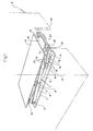
- a couple of two-wheel castors 2, 2 are mounted to the front and rear step portions 2, 2 respectively so that the carrier device can run on the floor.
- a top plate 3 is mounted above the base plate 3 for supporting the bottom of a TV stand A in carrying action.
- the top plate 3 has two lengthwisely extending side plates 4, 4 downwardly mounted thereto inside from the side ends while the base plate 1 has two lengthwisely extending side plates 5, 5 upwardly mounted thereto at the same so that the side plates 4, 4 can be opposite to the side plates 5, 5.
- Each pair of the side plates 4 and 5 are linked with each other by a main link mechanism 7 of one side which comprises a couple of support rods 6, 6 arranged in cross relationship for upward and downward movement of the top plate 3. More particularly, the two crossed support rods 6, 6 are pivotably coupled at the center to each other by a pivot pin 8 and at front end to the side plates 4 and 5 respectively by pins 9, 9.
- the support rods 6, 6 have at the rear end two pins 10, 10 fixedly mounted thereto respectively and movably fitted into lengthwisely extending slots 11, 11 provided in their respective side plates 4 and 5.
- the two, upper and lower, pins 9, 9 in the front are coupled to connecting rods 12 and 13 respectively which are in turn linked by a pin 16 to a driver rod 14.
- the connecting rods 12 and 13 and the driver rod 14 constitute in combination a sub-link mechanism 15 of one side, in which the connecting rods 12 and 13 are pivoted on the pin 16 together with the driver rod 14 and can also move about their respective pins 9, 9.
- the connecting rod 13 has a pin 17 mounted thereon close to the pin 16 for fixed coupling with the driver rod 14.
- the two, left and right, driver rods 14, 14 are coupled at front end to each other by a traverse bar 18 extending transversely.
- a lever 20 having at distal end a pedal 19 pivotably mounted thereon is mounted by a pin 21 on an off-center portion of the traverse bar 18 so that it can turn about the pin 21.
- the pedal 19 and the lever 20 are horizontally folded down to be accommodated beneath the top plate 3.
- the pedal 19 is inserted for lock on into between the top plate 3 and a stopper 22 which is mounted to the bottom surface of the top plate 3 and extends horizontally to the front while the top plate 3 remains lifted down.
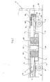
- a movable cylindrical member 23 is downwardly mounted to the center bottom surface of the top plate 3 for telescopic movement on a stationary cylindrical member 24 which is fixedly mounted upright on the center upper surface of the base plate 1.
- a pair of compression coil springs 25, 25 fixedly mounted between the base plate 1 and the top plate 3 and spaced a given distance from the movable and stationary cylindrical members 23 and 25 to the front and the rear respectively.
- the movable cylindrical member 23 accommodates a support shaft 26 which is fixedly mounted at uppermost end to the bottom surface of the top plate 3 so that it can downwardly extend throughout the inside space 23a of the cylindrical member 23.
- the support shaft 26 has a small diameter region 26a provided in the distal lowermost end thereof for accepting a collar 27 in fitting engagement. More specifically, the collar 27 is rotatably retained by a nut 29 screwed onto a thread 28 arranged in the distal end of the small diameter portion 26a.
- the collar 27 has a plurality of fins 30 mounted at equal intervals to the outer circumferential surface thereof.
- Each fin 30 has two, left and right, vertically extending side walls and two, upper and lower walls thereof in which the upper wall is sloped down from the right to the left thus forming a projection 30a of single-blade shape and the lower wall is pointed at the center and divided into two sloping sides thus forming an inverted V-shaped projection 30b.
- the stationary cylindrical member 24 has a receptor member 31 fixedly mounted therein to extend the inside space 24a thereof.
- the receptor member 31 is arranged into a cylindrical shape having a circumferential wall which is provided with vertically extending slots 32 of a given depth for accepting the fins 30 respectively so that the fins 30 when moved in can slide therealong upward and downward. Between the two adjacent deep slots 32, 32 forms each projection 33 of the receptor member 30 which has at uppermost end a V-shaped recess 34 for sustaining the lower projection 30b of each fin 30.
- a guide ring 35 is mounted to the uppermost end of the inner wall of the stationary cylindrical member 24 thus downwardly extending in the inner space 24a of the same.
- the guide ring 35 is adapted for guiding the vertical movement of the support shaft 26 and has a lower end thereof arranged in sawtooth shape thus providing a plurality of engaging recesses 36 therein for engagement with the upper, single-blade shaped projections 30a of the fins 30.
- the engaging recesses 36 are aligned to come opposite to the deep slots 32 and the V-shaped recesses 34 of the receptor member 31 alternately.
- the vertical wall 36a of each engaging recess 36 comes a bit on the left of the right wall 30c of the corresponding fin 30.
- the single-blade shaped projection 30a of the fin 30 rightwardly moves along the sloping wall 36b of the recess 36 to the deepest point of the same. This movement allows the fins 30 to rotate only in one (rightward) direction. Accordingly, the receptor member 31 and the guide ring 35 are spaced from each other a given distance for permitting free rotation of the collar 27.
- the total yielding force of the two compression coil springs 25, 25 are determined to a rate a bit less than the load of the TV stand A.
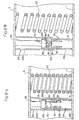
- the pedal 19 For carrying the TV stand A, the pedal 19 is pulled out through an opening 37 provided in the lower side of the TV stand A as shown in Fig.3 and pressed down.
- the downward action of the petal 19 triggers the movement of the sub-link mechanisms 15, 15 which in turn and actuates the main link mechanisms 7, 7 to lift up the top plate 3 with the help of the yielding force of the coil springs 25, 25.
- the fins 30 of the collar 27 engaged with the deep slots 32 of the receptor member 31 are moved upward and rotate rightward with their single-blade shaped projections 30a being slid directly along the corresponding sloping walls 36b of the engaging recesses 36 of the guide ring 35 prior to being fitted into the deepest points of the engaging recesses 36 for engagement as shown in Fig.8-b
- the top plate 3 When the pedal 19 is released, the top plate 3 is lowered by the weight of the TV stand A. As the inverted V-shaped projections 30b of the fins 30 now come into engagement with the V-shaped recesses 34 of the projections 33 of the receptor member 31, the TV stand A remains elevated up from the floor as shown in Fig.8-c. Accordingly, the castors 2, 2 become movable and the TV stand A will be carried to a desired location.
- the pedal 19 When the TV stand A comes to the desired location, the pedal 19 is lightly pressed down. Then, the fins 30 of the collar 27 come into engagement with the engaging recesses 36 of the guide ring 35, as shown in Fig.8-d, after their upper projections 30a are slid directly on the sloping walls 36b of the engaging recesses 36 for rightward rotation.
- the releasing of the pedal 19 causes the coil springs 25, 25 to be compressed by the weight of the TV stand A and thus, the fins 30 move downward into the deep slots 32 of the receptor member 31 for seating the TV stand A on the floor as shown in Fig.8-a.
- the carrier device of the present invention can carry bulky indoor appliances including a refrigerator and a music organ and outdoor articles such as garbage containers. If a load to be carried is large in the bottom area or long in the overall length, a couple of the carrier devices of the present invention will be used for supporting the two ends respectively.
- the compression coil springs mounted between the top and base plates are intended for ease of lifting operation and without them, the lifting action will be executed by means of the lever movement with the pedal. In this case, unwanted elevating of the top plate triggered by exterior force or unnecessary lifting of a load up from the floor will be avoided. If any, the compressing coil springs may be replaced with other urging means including as leaf springs.
Landscapes
- Engineering & Computer Science (AREA)
- Chemical & Material Sciences (AREA)
- Combustion & Propulsion (AREA)
- Transportation (AREA)
- Mechanical Engineering (AREA)
- Legs For Furniture In General (AREA)
- Accommodation For Nursing Or Treatment Tables (AREA)
Applications Claiming Priority (2)
| Application Number | Priority Date | Filing Date | Title |
|---|---|---|---|
| JP183749/90 | 1990-07-11 | ||
| JP2183749A JPH0611607B2 (ja) | 1990-07-11 | 1990-07-11 | 重量物の移動装置 |
Publications (1)
| Publication Number | Publication Date |
|---|---|
| EP0466438A1 true EP0466438A1 (fr) | 1992-01-15 |
Family
ID=16141307
Family Applications (1)
| Application Number | Title | Priority Date | Filing Date |
|---|---|---|---|
| EP91306188A Ceased EP0466438A1 (fr) | 1990-07-11 | 1991-07-08 | Dispositif porteur pour des charges lourdes |
Country Status (3)
| Country | Link |
|---|---|
| US (1) | US5131501A (fr) |
| EP (1) | EP0466438A1 (fr) |
| JP (1) | JPH0611607B2 (fr) |
Cited By (6)
| Publication number | Priority date | Publication date | Assignee | Title |
|---|---|---|---|---|
| US7918637B2 (en) * | 2007-05-25 | 2011-04-05 | Toyota Motor Engineering & Manufacturing North America, Inc. | Assist device for a tire and wheel assembly |
| CN102101501A (zh) * | 2009-12-17 | 2011-06-22 | Bt产品公司 | 包括竖向悬置的枢转平台的工业卡车 |
| CN102101502A (zh) * | 2009-12-17 | 2011-06-22 | Bt产品公司 | 包括具有用于枢转平台的操作元件的枢转平台的工业卡车 |
| CN103879472A (zh) * | 2012-12-19 | 2014-06-25 | 金宝电子工业股份有限公司 | 驱动装置与搬运车 |
| FR3034090A1 (fr) * | 2015-03-27 | 2016-09-30 | A C E Ingenierie | Systeme de levage d'un vehicule et procede de maintenance d'un vehicule mettant en œuvre un tel systeme de levage |
| EP3176125B1 (fr) * | 2015-12-03 | 2018-10-03 | The Raymond Corporation | Système de suspension pour un chariot de manutention avec une suspension de sol |
Families Citing this family (27)
| Publication number | Priority date | Publication date | Assignee | Title |
|---|---|---|---|---|
| US5193649A (en) * | 1992-06-23 | 1993-03-16 | Steven Lee | Platform car |
| DE4336662A1 (de) * | 1993-10-27 | 1995-05-04 | Stamm Johann | Scherenhubtisch |
| US5882774A (en) | 1993-12-21 | 1999-03-16 | Minnesota Mining And Manufacturing Company | Optical film |
| JP3178304B2 (ja) | 1994-11-11 | 2001-06-18 | 株式会社デンソー | 指針装置 |
| US5588377A (en) * | 1995-04-25 | 1996-12-31 | Fleetwood Enterprises, Inc. | Convertible table configurable between expanded and compressed positions |
| US5957649A (en) * | 1997-02-05 | 1999-09-28 | Herculift Technologies, Inc. | Lift dolly for use in conjunction with stand-mounted power tools and the like |
| JP3539885B2 (ja) * | 1999-03-31 | 2004-07-07 | Jfeスチール株式会社 | 炉体リングブロックの移動式吊換装置及び高炉炉体解体方法並びに高炉炉体構築方法 |
| US6789785B2 (en) * | 2002-01-23 | 2004-09-14 | Shinn Fu Corporation | Hydraulic lifting device with a rapid mechanical lift to chassis of vehicle |
| US6679479B1 (en) * | 2002-06-27 | 2004-01-20 | Steel Equipment Specialists, Llc | Scissor lift mechanism |
| US6997424B2 (en) * | 2003-03-18 | 2006-02-14 | Atkinson Jr Ronald Neil | Lifting apparatus |
| CA2930716C (fr) | 2004-05-17 | 2020-03-24 | Stertil B.V. | Un couvercle mobile destine a couvrir une fosse |
| US7331425B2 (en) | 2004-07-09 | 2008-02-19 | Gm Global Technology Operations, Inc. | Lift machine |
| WO2006076099A2 (fr) * | 2004-12-08 | 2006-07-20 | Ceres, Inc. | Sequences nucleotidiques et polypeptides correspondants permettant de moduler la taille et la biomasse de plantes |
| US20080056871A1 (en) * | 2006-07-10 | 2008-03-06 | Morgan Edwin M | Lift dolly |
| US8272830B2 (en) * | 2008-10-07 | 2012-09-25 | Applied Materials, Inc. | Scissor lift transfer robot |
| US9691650B2 (en) * | 2009-09-29 | 2017-06-27 | Applied Materials, Inc. | Substrate transfer robot with chamber and substrate monitoring capability |
| US9296596B2 (en) | 2012-10-15 | 2016-03-29 | Cameron Lanning Cormack | Hybrid wedge jack/scissor lift lifting apparatus and method of operation thereof |
| US20140169922A1 (en) * | 2012-12-18 | 2014-06-19 | Frank Charles Cozza | Cart with lifting system and omnidirectional wheels |
| US9630819B2 (en) * | 2013-11-18 | 2017-04-25 | Andrew H. Ong | Low rider wheel jack |
| US10918216B2 (en) | 2016-03-04 | 2021-02-16 | Atkinson Ergonomic Solutions | System and method for raising a bed off the floor |
| JP7040738B2 (ja) * | 2017-12-08 | 2022-03-23 | 株式会社山一精工 | 駆動輪ユニットの台車用連結機構 |
| TWI672090B (zh) * | 2018-03-12 | 2019-09-11 | 緯創資通股份有限公司 | 轉接板平移機構及電子設備 |
| CN108840125A (zh) * | 2018-05-14 | 2018-11-20 | 东莞市联洲知识产权运营管理有限公司 | 一种矿物输送车内的导流装置 |
| CN110803209A (zh) * | 2019-10-30 | 2020-02-18 | 邳州市硕益农业发展有限公司 | 一种农产品运输装置 |
| US20210269295A1 (en) * | 2020-02-28 | 2021-09-02 | Cleverosity Design Group, LLC | Personal Elevating Platform |
| CN113651019A (zh) * | 2021-07-21 | 2021-11-16 | 中国长城科技集团股份有限公司 | 服务器搬运装置 |
| US20240308829A1 (en) * | 2023-03-15 | 2024-09-19 | Global Industrial Distribution Inc. | Retention system for spring-loaded lift |
Citations (4)
| Publication number | Priority date | Publication date | Assignee | Title |
|---|---|---|---|---|
| DE311208C (fr) * | ||||
| US2495046A (en) * | 1947-04-08 | 1950-01-17 | Remington Rand Inc | Truck for record trays |
| US3904853A (en) * | 1974-01-31 | 1975-09-09 | R F Shoup Corp | Stand for transporting and storing a machine |
| DE3502641A1 (de) * | 1985-01-26 | 1986-07-31 | Mannesmann AG, 4000 Düsseldorf | Scherenhubvorrichtung |
Family Cites Families (2)
| Publication number | Priority date | Publication date | Assignee | Title |
|---|---|---|---|---|
| SE449352B (sv) * | 1984-11-28 | 1987-04-27 | Bertil Persson | Lyftanordning, foretredesvis en fatvendare, vilken foretredesvis er lyft- och forflyttbar med hjelp av en lyftvagn |
| JPH0640227Y2 (ja) * | 1988-03-20 | 1994-10-19 | 杉安工業株式会社 | コンテナ移乗用リフト |
-
1990
- 1990-07-11 JP JP2183749A patent/JPH0611607B2/ja not_active Expired - Fee Related
-
1991
- 1991-07-08 EP EP91306188A patent/EP0466438A1/fr not_active Ceased
- 1991-07-09 US US07/727,215 patent/US5131501A/en not_active Expired - Fee Related
Patent Citations (4)
| Publication number | Priority date | Publication date | Assignee | Title |
|---|---|---|---|---|
| DE311208C (fr) * | ||||
| US2495046A (en) * | 1947-04-08 | 1950-01-17 | Remington Rand Inc | Truck for record trays |
| US3904853A (en) * | 1974-01-31 | 1975-09-09 | R F Shoup Corp | Stand for transporting and storing a machine |
| DE3502641A1 (de) * | 1985-01-26 | 1986-07-31 | Mannesmann AG, 4000 Düsseldorf | Scherenhubvorrichtung |
Non-Patent Citations (1)
| Title |
|---|
| PATENT ABSTRACTS OF JAPAN vol. 14, no. 96 (C-692)(4039) February 22, 1990 & JP-A-1 305 904 (KOICHI YOSHIKAWA ) December 11, 1989 * |
Cited By (7)
| Publication number | Priority date | Publication date | Assignee | Title |
|---|---|---|---|---|
| US7918637B2 (en) * | 2007-05-25 | 2011-04-05 | Toyota Motor Engineering & Manufacturing North America, Inc. | Assist device for a tire and wheel assembly |
| CN102101501A (zh) * | 2009-12-17 | 2011-06-22 | Bt产品公司 | 包括竖向悬置的枢转平台的工业卡车 |
| CN102101502A (zh) * | 2009-12-17 | 2011-06-22 | Bt产品公司 | 包括具有用于枢转平台的操作元件的枢转平台的工业卡车 |
| CN102101502B (zh) * | 2009-12-17 | 2015-04-01 | Bt产品公司 | 舵柄臂卡车 |
| CN103879472A (zh) * | 2012-12-19 | 2014-06-25 | 金宝电子工业股份有限公司 | 驱动装置与搬运车 |
| FR3034090A1 (fr) * | 2015-03-27 | 2016-09-30 | A C E Ingenierie | Systeme de levage d'un vehicule et procede de maintenance d'un vehicule mettant en œuvre un tel systeme de levage |
| EP3176125B1 (fr) * | 2015-12-03 | 2018-10-03 | The Raymond Corporation | Système de suspension pour un chariot de manutention avec une suspension de sol |
Also Published As
| Publication number | Publication date |
|---|---|
| US5131501A (en) | 1992-07-21 |
| JPH0611607B2 (ja) | 1994-02-16 |
| JPH0472208A (ja) | 1992-03-06 |
Similar Documents
| Publication | Publication Date | Title |
|---|---|---|
| US5131501A (en) | Carrier device for heavy load | |
| US4194452A (en) | Convertible table | |
| US5050933A (en) | Stacking chair with collapsible arms | |
| JPH0725076Y2 (ja) | 高さ調整のできる背もたれ付き椅子、特に事務椅子 | |
| US20050230574A1 (en) | Keyboard instrument support with adjustable ability | |
| EP0637424B1 (fr) | Lit | |
| US3806218A (en) | Stack storage and lifter device | |
| US20250195938A1 (en) | Angle-adjustable smith machine | |
| JPH0380810A (ja) | 室内昇降構造体 | |
| CN212995542U (zh) | 一种折叠式家庭看护椅扶手 | |
| CN216907406U (zh) | 一种隐藏式茶几沙发 | |
| CN222722669U (zh) | 一种挂壁式可升降调节床头柜 | |
| CN215456820U (zh) | 一种升降稳定调节机构及座椅 | |
| JP2600806Y2 (ja) | 上下可動物体の任意位置停止機構及びそれを用いた可動吊り棚装置 | |
| JPH09154643A (ja) | 昇降式収納棚 | |
| KR20080096742A (ko) | 수납공간 인출승강장치 | |
| CN221759467U (zh) | 一种电气自动升降结构 | |
| JPH09295797A (ja) | 物体の昇降装置 | |
| JPH0636760Y2 (ja) | ワークステーションテーブル | |
| GB2254780A (en) | Transformable seat and table unit | |
| KR102535281B1 (ko) | 드레스룸용 행거의 높이조절장치 | |
| JPH0636758Y2 (ja) | ワークステーションテーブル | |
| JPH026939Y2 (fr) | ||
| JPH08239043A (ja) | 重量物搬送方法 | |
| CN213414900U (zh) | 一种仓库笼用堆叠支撑结构 |
Legal Events
| Date | Code | Title | Description |
|---|---|---|---|
| PUAI | Public reference made under article 153(3) epc to a published international application that has entered the european phase |
Free format text: ORIGINAL CODE: 0009012 |
|
| AK | Designated contracting states |
Kind code of ref document: A1 Designated state(s): DE FR GB IT SE |
|
| 17P | Request for examination filed |
Effective date: 19920713 |
|
| 17Q | First examination report despatched |
Effective date: 19931001 |
|
| STAA | Information on the status of an ep patent application or granted ep patent |
Free format text: STATUS: THE APPLICATION HAS BEEN REFUSED |
|
| 18R | Application refused |
Effective date: 19940731 |