EP0473945A2 - Gerät zur Messung der Entfernung zwischen Fahrzeugen - Google Patents
Gerät zur Messung der Entfernung zwischen Fahrzeugen Download PDFInfo
- Publication number
- EP0473945A2 EP0473945A2 EP91113033A EP91113033A EP0473945A2 EP 0473945 A2 EP0473945 A2 EP 0473945A2 EP 91113033 A EP91113033 A EP 91113033A EP 91113033 A EP91113033 A EP 91113033A EP 0473945 A2 EP0473945 A2 EP 0473945A2
- Authority
- EP
- European Patent Office
- Prior art keywords
- image
- distance
- window
- car
- preceding car
- Prior art date
- Legal status (The legal status is an assumption and is not a legal conclusion. Google has not performed a legal analysis and makes no representation as to the accuracy of the status listed.)
- Withdrawn
Links
Images

Classifications
-
- G—PHYSICS
- G05—CONTROLLING; REGULATING
- G05D—SYSTEMS FOR CONTROLLING OR REGULATING NON-ELECTRIC VARIABLES
- G05D1/00—Control of position, course, altitude or attitude of land, water, air or space vehicles, e.g. using automatic pilots
- G05D1/02—Control of position or course in two dimensions
- G05D1/021—Control of position or course in two dimensions specially adapted to land vehicles
- G05D1/0231—Control of position or course in two dimensions specially adapted to land vehicles using optical position detecting means
- G05D1/0246—Control of position or course in two dimensions specially adapted to land vehicles using optical position detecting means using a video camera in combination with image processing means
- G05D1/0251—Control of position or course in two dimensions specially adapted to land vehicles using optical position detecting means using a video camera in combination with image processing means extracting 3D information from a plurality of images taken from different locations, e.g. stereo vision
-
- G—PHYSICS
- G01—MEASURING; TESTING
- G01S—RADIO DIRECTION-FINDING; RADIO NAVIGATION; DETERMINING DISTANCE OR VELOCITY BY USE OF RADIO WAVES; LOCATING OR PRESENCE-DETECTING BY USE OF THE REFLECTION OR RERADIATION OF RADIO WAVES; ANALOGOUS ARRANGEMENTS USING OTHER WAVES
- G01S11/00—Systems for determining distance or velocity not using reflection or reradiation
- G01S11/12—Systems for determining distance or velocity not using reflection or reradiation using electromagnetic waves other than radio waves
-
- G—PHYSICS
- G05—CONTROLLING; REGULATING
- G05D—SYSTEMS FOR CONTROLLING OR REGULATING NON-ELECTRIC VARIABLES
- G05D1/00—Control of position, course, altitude or attitude of land, water, air or space vehicles, e.g. using automatic pilots
- G05D1/02—Control of position or course in two dimensions
- G05D1/021—Control of position or course in two dimensions specially adapted to land vehicles
- G05D1/0287—Control of position or course in two dimensions specially adapted to land vehicles involving a plurality of land vehicles, e.g. fleet or convoy travelling
- G05D1/0289—Control of position or course in two dimensions specially adapted to land vehicles involving a plurality of land vehicles, e.g. fleet or convoy travelling with means for avoiding collisions between vehicles
Definitions
- the present invention relates to an apparatus for detecting the distance between a preceding car and one's own car optically and continuously by image sensors.
- Sho-63-38085 (1988) and Sho-63-46363 (1988) and the like disclose apparatus for optically detecting the distance between cars going in the same direction by image sensors.
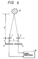
- discrete image sensors 3 and 4 at the respective positions of focal length f of the lenses 1 and 2 and a signal processor 30 for sequentially shifting the picture signals given from the image sensors 3 and 4 in order to electrically superpose them.
- a distance R up to an object 31 is obtained from the shift quantity l taken when the two picture signals become best synchronized on the principle of triangulation in terms of
- Japanese Examined Patent Publication No. Sho-60-33352 (1985) discloses a technique of tracking the preceding car image picked up by image sensors or the like.
- a target is tracked by an operator who is to set a tracking gate (window) encompassing the target thus tracked on a display screen while watching the display screen.
- a tracking gate windshield
- the conventional apparatus for detecting the distance between cars so arranged as described above make it possible to measure only the distance to the object which exists in the direction of optical axis of such an apparatus.
- the optical axis of the apparatus has to be adjusted to that direction.
- the problem is that when it is attempted to measure the distance to the preceding car as described above and if another car is going on the left or right of the preceding car in parallel, the driver will unable to perceive which one of the cars is intended for the measurement of the distance thereto.
- An object of the present invention is to solve the foregoing problems by providing an apparatus for detecting the distance between cars capable of continuously measuring the distance up to an object once the object is determined even if it is moving as far as it is within the visual field of the apparatus, of making distinguishable which one of the preceding cars is the object intended for the measurement of the distance thereto even though there exist a plurality of cars traveling ahead, and of simultaneously measuring the distance to another car traveling in parallel to the preceding car.
- An apparatus for detecting the distance between cars comprises two image sensors capable of imaging a wide visual field covering a preceding car, the sensor being arranged apart in the vertical direction, a display means for displaying the preceding car image picked up by either upper or lower image sensor, an image tracking device for tracking the preceding car image using a first window encompassing the preceding car image, and a distance computing means for computing the distance to an object encompassed by a second window set adjacent to the first window.
- the image sensors according to the present invention are used for imaging a preceding car in a wide visual field including the preceding car in order for that preceding car image picked up by the upper and lower image sensors to be displayed on the display means.
- the distance computing means is so operated as to encompass the preceding car image in the first window and then the image tracking means is employed for tracking the preceding car image to detect the shifting of the upper picture signal from the corresponding lower one, with the picture signal in the first window as a reference signal, whereby the distance between one's own car and the preceding car is computed.
- the shifting of the upper picture signal from the corresponding lower one is detected, whereby the distance to the object encompassed by the second window is computed.
- Fig. 1 is a block diagram illustrating the constitution of an embodiment.
- like reference characters designate like elements of Fig. 6.
- lenses 1 and 2 which are arranged apart by a base length of L, respectively form an upper and a lower optical system with tow-dimensional image sensors 3 and 4 corresponding to the respective lenses 1 and 2, the image sensors 3 and 4 being provided at the respective positions of focal length f of the lenses 1 and 2.
- Numerals 6 and 7 represent analog/digital converters (hereinafter called A/D) for digitalizing the picture signals picked up by the image sensors 3 and 4, respectively.
- A/D analog/digital converters
- the outputs of the A/D converters 6 and 7 are stored in respective memories 8 and 9, the writing and reading of data to and from the memories 8 and 9 being controlled by a microcomputer 10 as a distance computing means.
- the image picked up by the image sensor 4 is displayed on a display screen 11 by means of the data read from the memory 9.
- the display screen 11 is used as a display means and controlled by the microcomputer 10.
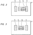
- Numeral 12 designates an image tracking device. As shown in Fig. 3, the image tracking device 12 forms on the display screen 11 a first window 14 for use in tracking a preceding car image 5a, a second and a third window 15 and 16 adjacent to the first window 14 and operates to track the preceding car image 5a encompassed with the first window 14.
- An image tracking instruction switch 13 in Fig. 1 is operated by the driver involved.
- the driver turns on the image tracking instruction switch 13 when the preceding car image 5a is completely accommodated in the first window in this condition as shown in Fig. 3, the first window 14 will stubbornly accompany the movement of the preceding car image 5a however, diversely the latter moves.
- the function of tracking the preceding car image 5a is thus performed automatically by the first window 14.
- the second window 15 and the third window 16 are also caused to move simultaneously.
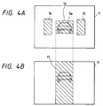
- the microcomputer 10 reads from the memory 9 a pixel signal in the first window 14 tracking the preceding car image 5a to make it a reference signal for computing the distance therebetween.
- the microcomputer 10 selects an area corresponding to the first window 14 from the memory 8 in which the picture signal derived from the lower image sensor 3 has been stored and while sequentially shifting the picture signal in the memory 8 by a pixel each time with respect to the reference signal, step by step computes the total of the absolute value of the difference in signal type between the upper and the lower pixel in combination.
- the position of an image best matching what is in the first window 14 is obtained by shifting one pixel at a time.
- the then area concerned in computation with resect to the reference signal in the first window 14 as shown in Fig. 4A is an area 17 corresponding to the position of the first window 14 with respect to the image of the memory 8 shown in Fig. 4B.
- n pixel as the shift amount of the pixel when the total absolute value of the difference signal obtained by comparison the upper and the lower pixels becomes minimum
- p as the pixel pitch
- L as the base length of the optical systems
- f as the focal length of the lenses 1 and 2
- R as the distance up to the preceding car 5
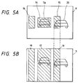
- the microprocessor 10 selects an operation area 18 (Fig. 5B) of the picture in the memory 8, the operation area 18 corresponding to that in the second window 15 in the memory 9, with the picture signal in the second window 15 as a reference signal, obtains the position of an image best matching the image in the second window 15 in the operation area 18, and computes the distance between the additional preceding car and one's own car.
- the distance to each preceding car can be detected even when a plurality of preceding cars are traveling.
- the objects caught in the respective second and third windows 15, 16 adjacent to the first window 14 for tracking the picture of the preceding car 5 are, as shown in Fig. 5B, subjected to picture comparisons in the operation areas 18 and 19 respectively corresponding to the second and third windows 15 and 16.
- the distance to such an object can thus be measured on a window basis.
- the number of windows may be increased when it is desired to keep a wide visual field ahead of one's own car under close observation.
- the size and shape of the window may be varied optionally in accordance with an object and are not limited to those defined in the embodiment shown.
- the preceding car image picked up by the image sensors for imaging the preceding car substantially using the pair of optical systems vertically arranged is display on the display means and the picture tracking device is used to track the preceding car image in the first window.
- the second window is set adjacent to the first window and, with the picture signals in these windows as the reference signals, the shifting of the upper picture signal from the corresponding lower one is detected so as to compute the distance between one's own car and the preceding car from window to window. Even while a plurality of cars are traveling ahead, a target preceding car is distinguished from the remaining ones and the distance to each of them is rendered detectable.
- the driver is allowed to properly monitor which one of the preceding cars he keeps track of while detecting the distance thereto.
Landscapes
- Engineering & Computer Science (AREA)
- Physics & Mathematics (AREA)
- Radar, Positioning & Navigation (AREA)
- Remote Sensing (AREA)
- General Physics & Mathematics (AREA)
- Electromagnetism (AREA)
- Computer Vision & Pattern Recognition (AREA)
- Aviation & Aerospace Engineering (AREA)
- Automation & Control Theory (AREA)
- Multimedia (AREA)
- Measurement Of Optical Distance (AREA)
- Image Processing (AREA)
Applications Claiming Priority (2)
| Application Number | Priority Date | Filing Date | Title |
|---|---|---|---|
| JP2234683A JP2508904B2 (ja) | 1990-09-04 | 1990-09-04 | 車間距離検出装置 |
| JP234683/90 | 1990-09-04 |
Publications (2)
| Publication Number | Publication Date |
|---|---|
| EP0473945A2 true EP0473945A2 (de) | 1992-03-11 |
| EP0473945A3 EP0473945A3 (en) | 1992-06-17 |
Family
ID=16974809
Family Applications (1)
| Application Number | Title | Priority Date | Filing Date |
|---|---|---|---|
| EP19910113033 Withdrawn EP0473945A3 (en) | 1990-09-04 | 1991-08-02 | Apparatus for detecting distance between cars |
Country Status (3)
| Country | Link |
|---|---|
| US (1) | US5168355A (de) |
| EP (1) | EP0473945A3 (de) |
| JP (1) | JP2508904B2 (de) |
Cited By (1)
| Publication number | Priority date | Publication date | Assignee | Title |
|---|---|---|---|---|
| EP0567013A1 (de) * | 1992-04-20 | 1993-10-27 | Mitsubishi Denki Kabushiki Kaisha | Vorrichtung zum Bestimmen des Abstandes zwischen Fahrzeugen |
Families Citing this family (22)
| Publication number | Priority date | Publication date | Assignee | Title |
|---|---|---|---|---|
| JPH04331311A (ja) * | 1991-01-24 | 1992-11-19 | Mitsubishi Electric Corp | 車間距離検出装置 |
| JP2635246B2 (ja) * | 1991-08-28 | 1997-07-30 | 三菱電機株式会社 | 先行車追尾用車間距離検出装置 |
| JP2800531B2 (ja) * | 1992-02-28 | 1998-09-21 | 三菱電機株式会社 | 車両用障害物検出装置 |
| JPH0696397A (ja) * | 1992-09-16 | 1994-04-08 | Mitsubishi Electric Corp | 画像追尾装置および画像追尾方法 |
| US5877897A (en) | 1993-02-26 | 1999-03-02 | Donnelly Corporation | Automatic rearview mirror, vehicle lighting control and vehicle interior monitoring system using a photosensor array |
| US6822563B2 (en) | 1997-09-22 | 2004-11-23 | Donnelly Corporation | Vehicle imaging system with accessory control |
| US6891563B2 (en) | 1996-05-22 | 2005-05-10 | Donnelly Corporation | Vehicular vision system |
| US7655894B2 (en) | 1996-03-25 | 2010-02-02 | Donnelly Corporation | Vehicular image sensing system |
| AU2003225228A1 (en) | 2002-05-03 | 2003-11-17 | Donnelly Corporation | Object detection system for vehicle |
| DE10343684A1 (de) * | 2003-09-20 | 2005-04-21 | Daimler Chrysler Ag | Verfahren zur Auswahl eines Zielfahrzeugs |
| US7526103B2 (en) | 2004-04-15 | 2009-04-28 | Donnelly Corporation | Imaging system for vehicle |
| US7881496B2 (en) | 2004-09-30 | 2011-02-01 | Donnelly Corporation | Vision system for vehicle |
| JP2007131178A (ja) * | 2005-11-10 | 2007-05-31 | Sumitomo Electric Ind Ltd | 障害物位置特定システム |
| WO2008024639A2 (en) | 2006-08-11 | 2008-02-28 | Donnelly Corporation | Automatic headlamp control system |
| JP2009225322A (ja) * | 2008-03-18 | 2009-10-01 | Hyundai Motor Co Ltd | 車両用情報表示システム |
| GB2491870B (en) * | 2011-06-15 | 2013-11-27 | Renesas Mobile Corp | Method and apparatus for providing communication link monito ring |
| US10661725B2 (en) | 2017-11-10 | 2020-05-26 | Denso Corporation | Camera module |
| US10406995B2 (en) | 2017-11-10 | 2019-09-10 | Denso Corporation | Camera module |
| US10534253B2 (en) | 2017-11-10 | 2020-01-14 | Denso Corporation | Camera module which includes lens units and configured to be mounted on inside of windshiled of vehicle |
| US10627606B2 (en) | 2017-11-10 | 2020-04-21 | Denso Corporation | Camera module |
| US10232800B1 (en) | 2017-11-10 | 2019-03-19 | Denson Corporation | Camera module |
| US11181816B2 (en) | 2017-11-10 | 2021-11-23 | Denso Corporation | Windshield-mounted camera module |
Family Cites Families (14)
| Publication number | Priority date | Publication date | Assignee | Title |
|---|---|---|---|---|
| DE3069857D1 (en) * | 1979-05-04 | 1985-02-07 | Gunter Lowe | Method of measuring shooting errors and shooting error measurement device for carrying out the method |
| JPS6033352A (ja) * | 1983-08-02 | 1985-02-20 | Kokusai Electric Co Ltd | 減圧cvd装置 |
| FR2566218B1 (fr) * | 1984-06-15 | 1988-06-24 | Sfim | Procede de traitement d'une image video pour la poursuite d'un objet lumineux et la protection de cette poursuite a l'encontre de brouilleurs en forme d'autres objets lumineux |
| JPS6144313A (ja) * | 1984-08-08 | 1986-03-04 | Nippon Denso Co Ltd | 距離測定装置 |
| JPS61182516A (ja) * | 1985-02-09 | 1986-08-15 | Canon Inc | 距離測定方法 |
| JPH07104159B2 (ja) * | 1986-07-19 | 1995-11-13 | スズキ株式会社 | 絶対車間距離検出方式 |
| JPH0671896B2 (ja) * | 1986-07-31 | 1994-09-14 | 日産自動車株式会社 | 車体後部構造 |
| IT1202534B (it) * | 1987-02-13 | 1989-02-09 | Tecnomare Spa | Apparecchiatura per il rilevamento in continuo della distanza da essa di un punto prefissato,anche mobile |
| JPS6435305A (en) * | 1987-07-31 | 1989-02-06 | Komatsu Mfg Co Ltd | Three-dimensional plane measuring instrument |
| JPH0638018B2 (ja) * | 1987-08-06 | 1994-05-18 | ホシザキ電機株式会社 | 冷凍装置用取付架台構造 |
| DE58902538D1 (de) * | 1988-05-19 | 1992-12-03 | Siemens Ag | Verfahren zur beobachtung einer szene und einrichtung zur durchfuehrung des verfahrens. |
| US4959714A (en) * | 1988-08-08 | 1990-09-25 | Hughes Aircraft Company | Segmentation method for terminal aimpoint determination on moving objects and apparatus therefor |
| KR930004880B1 (ko) * | 1989-03-07 | 1993-06-09 | 미쓰비시 덴끼 가부시기가이샤 | 추미식 차간거리 측정장치 |
| FR2655503B1 (fr) * | 1989-12-01 | 1992-02-21 | Thomson Csf | Systeme optoelectronique d'aide aux missions aeriennes d'attaque et de navigation. |
-
1990
- 1990-09-04 JP JP2234683A patent/JP2508904B2/ja not_active Expired - Fee Related
-
1991
- 1991-07-31 US US07/738,649 patent/US5168355A/en not_active Expired - Lifetime
- 1991-08-02 EP EP19910113033 patent/EP0473945A3/en not_active Withdrawn
Cited By (2)
| Publication number | Priority date | Publication date | Assignee | Title |
|---|---|---|---|---|
| EP0567013A1 (de) * | 1992-04-20 | 1993-10-27 | Mitsubishi Denki Kabushiki Kaisha | Vorrichtung zum Bestimmen des Abstandes zwischen Fahrzeugen |
| US5369590A (en) * | 1992-04-20 | 1994-11-29 | Mitsubishi Denki Kabushiki Kaisha | Inter-vehicle distance detecting device |
Also Published As
| Publication number | Publication date |
|---|---|
| JPH04113213A (ja) | 1992-04-14 |
| US5168355A (en) | 1992-12-01 |
| JP2508904B2 (ja) | 1996-06-19 |
| EP0473945A3 (en) | 1992-06-17 |
Similar Documents
| Publication | Publication Date | Title |
|---|---|---|
| EP0473945A2 (de) | Gerät zur Messung der Entfernung zwischen Fahrzeugen | |
| KR930004880B1 (ko) | 추미식 차간거리 측정장치 | |
| KR930004882B1 (ko) | 선행차추미용 차간거리 검출장치 | |
| EP0496411B1 (de) | Entfernungsbestimmungsgerät für Fahrzeuge | |
| JPH05296767A (ja) | 車間距離検出装置 | |
| JPH04313199A (ja) | 車間距離検出装置 | |
| JP2671615B2 (ja) | ガードレール検出装置 | |
| US5187537A (en) | Vehicle following apparatus | |
| US5321488A (en) | Inter-vehicle distance detecting device | |
| EP0546518B1 (de) | Vorrichtung zum Messen des Abstandes zwischen Fahrzeugen | |
| EP0529619B1 (de) | Entfernungsmesser für Abstand zwischen Fahrzeugen mit Nachführung des vorausfahrenden Fahrzeugs | |
| JP2927916B2 (ja) | 距離検出装置 | |
| EP0498416B1 (de) | Abstandsdetektionsvorrichtung zwischen Fahrzeugen | |
| JPH0754253B2 (ja) | 追尾式車間距離測定装置 | |
| EP0529558B1 (de) | Entfernungsmesser für Abstand zwischen Fahrzeugen | |
| JP2560147B2 (ja) | 車間距離検出装置 | |
| JP2527231B2 (ja) | 距離測定装置 | |
| JPH04313014A (ja) | 車間距離検出装置 | |
| JP3110191B2 (ja) | 車間距離測定装置 | |
| JPH04262500A (ja) | 車間距離検出装置 | |
| JPH0443911A (ja) | 車間距離検出装置 | |
| JPH087067B2 (ja) | 車庫入れ用後方監視装置 | |
| JPH03269313A (ja) | 車間距離検出装置 | |
| JPH03231111A (ja) | 先行車追尾用車間距離検出装置 | |
| JPH03231112A (ja) | 先行車追尾用車間距離検出装置 |
Legal Events
| Date | Code | Title | Description |
|---|---|---|---|
| PUAI | Public reference made under article 153(3) epc to a published international application that has entered the european phase |
Free format text: ORIGINAL CODE: 0009012 |
|
| AK | Designated contracting states |
Kind code of ref document: A2 Designated state(s): DE FR GB |
|
| PUAL | Search report despatched |
Free format text: ORIGINAL CODE: 0009013 |
|
| AK | Designated contracting states |
Kind code of ref document: A3 Designated state(s): DE FR GB |
|
| STAA | Information on the status of an ep patent application or granted ep patent |
Free format text: STATUS: THE APPLICATION IS DEEMED TO BE WITHDRAWN |
|
| 18D | Application deemed to be withdrawn |
Effective date: 19921218 |