EP0475640A2 - Source optique pour la commutation de polarisation, récepteur optique et système de transmission optique cohérent - Google Patents
Source optique pour la commutation de polarisation, récepteur optique et système de transmission optique cohérent Download PDFInfo
- Publication number
- EP0475640A2 EP0475640A2 EP91307937A EP91307937A EP0475640A2 EP 0475640 A2 EP0475640 A2 EP 0475640A2 EP 91307937 A EP91307937 A EP 91307937A EP 91307937 A EP91307937 A EP 91307937A EP 0475640 A2 EP0475640 A2 EP 0475640A2
- Authority
- EP
- European Patent Office
- Prior art keywords
- phase
- optical
- signal
- switching
- light
- Prior art date
- Legal status (The legal status is an assumption and is not a legal conclusion. Google has not performed a legal analysis and makes no representation as to the accuracy of the status listed.)
- Granted
Links
Images


Classifications
-
- H—ELECTRICITY
- H04—ELECTRIC COMMUNICATION TECHNIQUE
- H04B—TRANSMISSION
- H04B10/00—Transmission systems employing electromagnetic waves other than radio-waves, e.g. infrared, visible or ultraviolet light, or employing corpuscular radiation, e.g. quantum communication
- H04B10/50—Transmitters
- H04B10/516—Details of coding or modulation
- H04B10/532—Polarisation modulation
Definitions
- the present invention relates to coherent optical communication techniques and, more particularly, to a polarization switching light source, an optical receiver, and a coherent optical transmission system.
- coherent optical communication techniques in which heterodyne detection or homodyne detection is performed by utilizing the properties of light as a wave (e.g., T. Okoshi and K. Kikuchi, "Coherent Optical Fiber Communications", KTK Scientific Publishers, Tokyo, 1988).
- a local oscillation source is prepared on the reception side to receive a beat signal resulting from interference between signal light and local oscillation light and appearing in a photodetector. Since the spectrum purity of signal light or local oscillation light is higher than that in a conventional direct detection system, optical frequency division multiplexing (optical FDM) with high density can be realized.
- the first problem is associated with polarization matching
- signal light transmitted through an optical fiber varies in polarization state depending on the temperature of the fiber, a stress acting thereon, and other disturbances.
- a variation in polarization state of signal light corresponds to the intensity variation of a beat signal resulting from interference.
- the polarization states of signal light and local oscillation light are orthogonal, the resulting beat output becomes zero.
- (3) polarization diversity reception is widely used (e.g., L. G. Kazovsky, "Phase- and Polarization-Diversity Coherent Optical Techniques", Journal of Lightwave Technology, Vol. 7, No. 2, pp. 279 - 292, February 1989).
- two independent polarization components are separately received (multi-port reception), and the received components are electrically synthesized.
- the method requires a complicated optical system for a receiver, and also requires two light receivers and two intermediate frequency (IF) circuits.
- IF intermediate frequency
- problems are posed in terms of adjustment of an optical system, cost, and size.
- the characteristics of the respective reception ports such as transmission delay time, coupling efficiency, and gain must be matched with each other.
- This method has a receiving sensitivity lower than that of other methods by 3 dB and cannot be applied to a system of a high data rate, but the receivers are much simple. Therefore the method is expected to be applied to a subscriber's system and the like with a relatively low data rate.
- polarization scrambling (switching) light sources have been reported:
- the polarization bistable semiconductor laser (a) cannot be suitably applied to coherent optical communication because the wavelength of output light or the output power generally varies during a polarization switching operation.
- the external modulator (b) is not suitable for practical applications because it has various drawbacks, e.g., a large insertion loss, a large driving voltage, difficulty in high-speed switching, poor temperature characteristics, poor stability, and low reliability.
- the polarization switch based on laser frequency modulation (c) causes an increase in spectrum line width, resulting in difficulty in coherent detection. Since the problems with (a) and (b) seem to be apparent, only the problems with (c) will be described below with reference to the following examples.
- an oscillation frequency f L of the local oscillation laser is frequency-modulated by a rectangular wave to become f L1 in the first half of a one-bit time slot and f L2 in the second half.
- a beat signal (IF signal) based on signal light and local oscillation light generated by a photodiode is demodulated into a baseband signal by an IF circuit and a demodulation circuit.
- the main axis ( x axis) of the polarization maintaining optical fiber is inclined at 45° with respect to the polarization direction of the input local oscillation light.
- a phase retardation ⁇ (f) between the x- and y-axis polarization components of output light from the polarization maintaining optical fiber is 2 ⁇ LBf/c0.
- the polarization states (P1, P2) of light having a ⁇ difference in ⁇ are orthogonal. That is, a polarization switch for output light is realized.
- a frequency change occurs together with polarization switching of output light.
- DPSK differential phase shift keying
- ASK amplitude shift keying
- FSK frequency shift keying
- two IF frequencies appear in accordance with polarization states.
- AFC automatic frequency control
- R B ⁇ 1 Gb/s.
- the method described above requires a wide IF band and causes a great deterioration in sensitivity and hence is not suitable for practical applications.
- the drawback of the heterodyne detection scheme is that a receiver having a wide band is required because an IF band is used. Especially in transmission at a high bit rate, the band width of a receiver is a bottleneck. In addition, in consideration of the application of the scheme to a subscriber's system, even at a low bit rate, requirement of a wide band for a receiver is not preferable in terms of cost.
- phase diversity reception scheme e.g., L. G. Kazovsky, "Phase- and Polarization-Diversity Coherent Optical Techniques", Journal of Lightwave Technology, Vol. 7, No. 2, pp. 279 - 292, February 1989
- phase diversity reception scheme e.g., L. G. Kazovsky, "Phase- and Polarization-Diversity Coherent Optical Techniques", Journal of Lightwave Technology, Vol. 7, No. 2, pp. 279 - 292, February 1989
- components of a plurality of phases of signal light are independently received, and the received components are electrically synthesized in the same manner as in polarization diversity.
- a complicated arrangement is required, and the characteristics of the respective ports must be matched with each other.
- the arrangement for polarization diversity and phase diversity requires at least four optical receivers.
- phase switching reception may be employed (I. M. I. Habbab, J. M. Kahn, and L. J. Greenstein, "Phase-Insensitive Zero-IF Coherent Optical System Using Phase Switching", Electronics Letters, Vol. 24, No. 15, pp. 974 - 976, June 1988). Even the phase switching scheme is not free from the problem of polarization matching. In addition, no method of simultaneously performing phase switching and polarization switching has yet been established. (c) Problems associated with high density optical FDM
- the number of channels which can be multiplexed by an optical FDM is determined by a usable frequency (wavelength) band and an allowable channel interval.
- the frequency band is limited by the tuning range of an local oscillation source or the band of an optical system. Although the tuning range has been increased with the advances in variable-wavelength semiconductor lasers, it is not sufficiently wide yet.
- a reduction in channel interval is indispensable for the effective use of a wavelength band.
- the presence of an image component in an IF band limits a channel interval.
- a reception scheme (image removing receiver) for removing this image component has been proposed. However, if this scheme is combined with polarization diversity, the resulting arrangement is very complicated.
- Such an image removing receiver is disclosed in Terumi Chikama et al., "Optical Heterodyne Image Rejection Receiver", 1989 Spring National Convention Record, the Institute of Electronics, Information and Communication Engineers of Japan, Part 4, pp. 4 - 133, 1989.
- an optical system has a very complicated arrangement, and an electrical system also has a complicated arrangement with four balanced light receivers.
- the application of such a scheme to a multichannel optical CATV distribution system or an optical LAN is very difficult in terms of, e.g., reliability and cost.
- the problems in the practical application of the coherent optical communication scheme are associated with: (a) polarization matching, (b) phase noise and a receiver band width, and (c) a high density FDM.
- the methods based on the following means are regarded to be effective: (A) polarization diversity, (B) phase diversity, and (C) multi-port reception using an image removing receiver and the like.
- A polarization diversity
- B phase diversity
- C multi-port reception using an image removing receiver and the like.
- a complicated arrangement is required, and the characteristics of the respective ports must be matched with each other, thus undesirably restricting allowable characteristic specifications. If two or more of the methods (A), (B), and (C) are to be simultaneously performed, a very complicated arrangement is required.
- the gist of the present invention is that the direct phase modulation technique of a semiconductor laser is used to enable simple, easy, low-cost coherent switching reception in terms of the problems of polarization, phase, and image components.
- a polarization switching light source comprising (a) a semiconductor laser, (b) means for performing phase modulation by supplying a pulse current to the semiconductor laser, (c) a dividing device for dividing output light from the semiconductor laser into two branch components having substantially the same power, (d) a delay means for delaying one branch component with respect to the other branch component an integer of a phase modulation period, and (e) a mixing means for mixing the two branch components, the polarization axes thereof are set to be orthogonal at the mixing means.
- an optical receiver comprising (a) a local oscillation source, constituted by the polarization switching light source in the first aspect, the local oscillation source performing polarization switching upon switching of sub-time slots obtained by dividing a time slot T corresponding to a one-bit signal into not less than two portions, (b) a optical receiver for receiving a beat component, resulting from signal light and local oscillation light, as an electrical signal, (c) a detection circuit for detecting a received signal in each sub-time slot, and (d) an adding circuit for adding detection outputs in the respective sub-time slots within the time slot T.
- an optical receiver comprising (a) a local oscillation source, having means for performing phase modulation by supplying a pulse current to a semiconductor laser, the local oscillation source performing fixed phase switching between ⁇ /2 and - ⁇ /2 upon switching of phase sub-time slots TS obtained by dividing a time slot T corresponding to a one-bit signal into not less than three portions, (b) an optical receiving unit for receiving a beat component, resulting from local oscillation light and signal light, as an electrical signal, (c) means for dividing a beat output from the optical receiving unit into two output components, and delaying one output component with respect to the other output component by a predetermined amount, (d) an electrical 90° hybrid circuit for the two output components, and (f) a detection circuit for detecting an output from the 90° hybrid circuit.
- an optical receiver comprising (a) a local oscillation source, having means for per forming phase modulation by supplying a pulse current to a semiconductor laser, the local oscillation source per forming fixed phase switching between ⁇ /2 and - ⁇ /2 upon switching of phase sub-time slots obtained by dividing a time slot T corresponding to a one-bit signal into not less than two portions, (b) an optical receiving unit for receiving a beat component, resulting from local oscillation light and signal light, as an electrical signal, (c) means for dividing a beat output from the optical receiving unit into two output components, and delaying one output component with respect to the other output component by a predetermined amount, (d) an electrical 90° hybrid circuit for the two output components, (e) a signal path switching circuit, arranged on a stage before or after the 90° hybrid circuit, the signal path switching circuit switching signal paths of the 90° hybrid circuit in synchronism with a phase sub-time slot, and (f) a detector for detecting a signal
- a coherent optical transmission system comprising at least one of an optical transmitter and an optical receiver, the first optical transmitter having means for performing phase modulation by supplying a pulse current to a semiconductor laser, and the optical transmitter performing phase switching between ⁇ /2 and - ⁇ /2 upon switching of phase sub-time slots obtained by dividing a time slot T corresponding to a one-bit signal into not less than two portions, and the optical receiver including a local oscillation source constituted by a polarization switching light source in which a timing of polarization switching is set to cause different polarization states to independently appear in the same phase state in one time slot of signal light, an optical receiving unit for receiving a beat component, resulting from light from the local oscillation source and signal light from the optical transmitter, as an electrical signal, a detector for detecting a received signal in each sub-time slot, and means for adding detection outputs in new phase/ polarization sub-time slots, which are divided at timings of polarization switching and phase switching and have different polarization and phase
- a coherent optical transmission system capable of performing image rejection signal reception comprising at least one of an optical transmitter and an optical receiver, the optical transmitter having means for performing phase modulation by supplying a pulse current to a semiconductor laser, and the optical transmitter performing phase switching between ⁇ /2 and - ⁇ /2 upon switching of phase sub-time slots obtained by dividing a time slot T corresponding to a one-bit signal into not less than two components, and the optical receiver including a local oscillation source, an optical receiving unit for receiving a beat component, resulting from light from the local oscillation source and signal light from the optical transmitter, as an electrical signal, means for dividing a beat output from the optical receiving unit into two output components, and delaying one output component with respect to the other output component by a predetermine amount, an electrical 90° hybrid circuit for the two output components, and a detector for detecting an output signal from the 90° hybrid circuit.
- a coherent optical transmission system capable of performing image rejection signal reception comprising at least one of an optical transmitter and an optical receiver, the optical transmitter having means for performing phase modulation by supplying a pulse current to a semiconductor laser, and the optical transmitter performing phase switching between ⁇ /2 and - ⁇ /2 upon switching of phase sub-time slots obtained by dividing a time slot T corresponding to a one-bit signal into not less than two components, and the second optical receiver including a local oscillation source, an optical receiving unit for receiving a beat component, resulting from light from the local oscillation source and signal light from the optical transmitter, as an electrical signal, means for dividing a beat output from the optical receiving unit into two output components, and delaying one output component with respect to the other output component by a predetermine amount, an electrical 90° hybrid circuit for the two output components, a signal path switching circuit, arranged on a stage before or after the 90° hybrid circuit, the signal path switching circuit switching signal paths in synchronism with a phase sub-time slot of the
- the optical receiver according to the second, third, or fourth aspect of the present invention further includes a function for inhibiting signal detection at the instant when a frequency variation accompanying a phase variation of local oscillation light appears in an electrical beat signal.
- the optical receiver further includes an AFC function for detecting a difference between a beat frequency and a preset value thereof and controlling an oscillation frequency of a local oscillator to set the beat frequency to be a predetermined value only when a frequency variation accompanying a phase variation of local oscillation light does not appear in a beat signal.
- the local oscillation source has a function, constituted by a polarization switching light source, for adding detection outputs having different polarization states in one time slot.
- the optical receiver in the coherent optical transmission system according to the fifth, sixth, or seventh aspect of the present invention further includes a function for detecting a clock by detecting a pulse-like frequency variation accompanying phase switching of the optical transmitter.
- the coherent optical transmission system in which the local oscillation source is constituted by a polarization switching optical source, or the coherent optical transmission system according to the sixth or seventh aspect of the present invention which includes a function for adding detection outputs having different polarization states in one time slot, a pulse waveform, a pulse pattern, or a polarity is changed by pulse-like frequency modulation for phase switching performed by the optical transmitter and pulse-like frequency modulation for polarization switching performed by the local oscillator of the optical receiver.
- the optical receiver includes a function for identifying and detecting a pulse-like frequency variation accompanying polarization switching and a pulse-like frequency variation accompanying phase switching, and a function for controlling the timing of polarization switching by using the detected signals.
- the optical receiver in the coherent optical transmission system according to the fifth, sixth, or seventh aspect of the present invention further includes a function for inhibiting signal detection at the instant when a frequency variation accompanying a phase variation of signal light or local oscillation light appears in an electrical beat signal.
- the optical receiver further includes an AFC function for detecting a difference between a beat frequency and a preset value thereof and controlling the oscillation frequency of the local oscillator to set the beat frequency to be a predetermined value only when a frequency variation accompanying a phase variation of local oscillation light does not appear in an electrical beat signal.
- control is performed to match all the timings of phase switching of the respective optical transmitters with each other in the corresponding optical receivers.
- frequency modulation is performed in a pulse-like manner with a predetermined pulse pattern having a period T by directly supplying a pulse current to the semiconductor laser.
- ⁇ (t) an angular frequency deviation at time t
- phase modulation represented by the following equation is performed before and after the application of the pulse:
- This semiconductor laser output light is divided into branch components A and B.
- the propagation time of one branch component A is delayed with respect to the propagation time of the other branch component B by a predetermined time ⁇ .
- the branch components A and B are then synthesized in such a manner that their polarization states are orthogonal.
- a delay time difference ⁇ between the two branch components A and B is set to be a fraction of an integer of a period T of phase modulation, a change with a certain pattern periodically occurs at the period T.
- a change amount of one switching operation with ⁇ (t) is set to be, e.g., ⁇ ⁇ 2n ⁇ (n is an integer)
- two orthogonal polarization states are switched according to equation (1). If the system is adjusted such that the orthogonal polarization states appear at substantially the same probability in the period T, a constant beat can be obtained from light components having arbitrary polarization states in terms of an average time interval.
- the coherent optical receiver using the polarization switching light source according to the first aspect as a local oscillation source using the polarization switching light source according to the first aspect as a local oscillation source.
- a phase modulation pattern is set such that independent, different polarization states of local oscillation light always appear once or more in the one-bit time slot T of a transmitted signal.
- a polarization state is divided into two sub-time slots TS or more. If a beat component, resulting from this local oscillation light and signal light, is received and detected in each sub-time slot, and the detection outputs in the respective subtime slots are added (or averaged) within the time slot T, a signal output having a substantially constant magnitude can be obtained.
- the image rejection coherent optical receiver using the semiconductor laser capable of direct phase modulation as a local oscillation source.
- the local oscillation source performs phase modulation corresponding to an absolute value ⁇ /2 three times or more in the one-bit time slot T.
- a time slot is divided into a plurality of sub-time slots, each having a length T S .
- a beat component resulting from this local oscillation light and signal light, is received in each sub-time slot.
- the signal light contains a component ⁇ S1 having a frequency higher than a frequency ⁇ L of the local oscillation light and a component ⁇ S2 having a frequency lower than the frequency ⁇ L .
- the phase of the received beat signal is also shifted by ⁇ /2 in each subtime slot.
- the beat output in the first sub-time slot is represented by
- This beat output is divided into two components.
- One component is delayed with respect to the other component by T S .
- the two components are then added together while the phase of one component is shifted by ⁇ /2.
- an output X1 obtained by adding one branch component, which is delayed by T S , to the other branch component whose phase is shifted by 90° is represented by
- the optical receiver according to the fourth aspect of the present invention is a modification of the apparatus according to the third aspect.
- the local oscillation source performs phase switching alternately between ⁇ /2 and - ⁇ /2.
- at least two sub-time slots are required. Under the same conditions as those in the third aspect, the following light receiver outputs alternately appear in the respective sub-time slots:
- the light frequency greatly changes. This may cause an error in signal demodulation or an AFC operation.
- the optical receiver further includes a function for inhibiting signal detection at the instant when a frequency variation accompanying a phase variation of local oscillation light appears in an electrical beat signal, an increase in the number of errors in signal demodulation can be prevented because a beat signal in a switching state need not be used for signal demodulation.
- ⁇ T the total time required for switching in the time slot T
- a power penalty is caused.
- the power penalty can be reduced by decreasing ⁇ T/T.
- the light receiver further includes an AFC function for detecting the difference between a beat frequency and a preset value thereof and controlling the oscillation frequency of a local oscillator to set the beat frequency to be a predetermined value only when a frequency variation accompanying a phase variation of local oscillation light does not appear in a beat signal, a frequency variation of the local oscillation source can be suppressed because a beat signal in a switching state need not used for AFC.
- the coherent light transmission system which can simultaneously perform phase switching and polarization switching.
- Polarization sub-time slots are set such that two independent polarization states A and B always appear in the respective sub-time slots, in one time slot, which have two independent phase states.
- cos( ⁇ L t + ⁇ LA ) appears in a polarization sub-time slot A, whereas output light with the polarization state B having an electric field strength
- This local oscillation light is mixed with light from the optical transmitter, and the mixed light is received by the optical receiver.
- ⁇ A and ⁇ B satisfy 0 ⁇ ⁇ A ⁇ 1 and 0 ⁇ ⁇ B ⁇ 1, respectively.
- the following beat output components appear in correspondence with phase sub-time slots 1 and 2 and polarization subtime slots A and B:
- the coherent optical transmission system which performs phase switching with image rejection signal reception according to the third aspect by using the optical transmitter in place of the local oscillation source.
- the operation principle of this system is the same as that of the system according to the third aspect except that phase switching is performed by the optical transmitter instead of the local oscillation source. Note that an image component must also be phase-switched in synchronism with a desired signal component in the same manner.
- the coherent optical transmission system which performs phase switching with image rejection signal reception according to the fourth aspect by using the optical transmitter in place of the local oscillation source.
- the operation principle of this system is the same as that of the system according to the fourth aspect except that phase switching is performed by the optical transmitter instead of the local oscillation source. Note that an image component must also be phase-switched in synchronism with a desired signal component in the same manner.
- the local oscillation source is constituted by a polarization switching light source and has a function for adding detection outputs with different polarization states in one time slot.
- the light receiver of the coherent optical transmission system according to the sixth or seventh aspect is used for the coherent optical transmission system constituted by a combination of the image rejection function and the polarization switching function according to the second aspect. In this case, if phase switching for removing image components is performed by the optical transmitter while polarization switching is performed by the local oscillation source, image rejection signal reception can be performed without depending on the polarization state of signal light reaching the optical receiver.
- the coherent optical transmission system wherein the optical receiver further includes a function for detecting a clock by detecting a pulse-like frequency variation accompanying phase switching of the optical transmitter, thus extracting a clock from a frequency variation of an optical signal.
- a clock is to be extracted from a signal, since no periodic component appears in a clock if the value of the signal does not change, it is difficult to perform stable clock extraction.
- signal light is frequency-modulated in the form of a pulse to perform periodic phase switching regardless of the value of the signal. By using such signal light, a stable clock extracting operation can be performed regardless of the value of a signal.
- the coherent optical transmission system according to the fifth aspect of the present invention in which the local oscillation source is constituted by a polarization switching light source, or the coherent optical transmission system according to the sixth or seventh aspect, which has a function for adding detection outputs with different polarization states in on time slot, includes a function for changing a pulse waveform, a pulse pattern, or a polarity by means of pulse-like frequency modulation for phase switching performed by the optical transmitter and pulse-like frequency modulation for polarization switching provided for the local oscillator of the optical receiver.
- the optical receiver includes a function for identifying and detecting a pulse-like frequency variation accompanying polarization switching and a pulse-like frequency variation accompanying phase switching, and a function for controlling the timing of polarization switching by using the detected signal.
- the signal light is frequency-modulated in the form of a pulse for phase switching while the local oscillation light is frequency-modulated in the form of a pulse for polarization switching, both pulses appear in the beat signals. If the waveform, pulse pattern, or polarity of each frequency-modulated pulse is changed in advance, the two types of frequency modulation can be discriminated from each other upon detection of a frequency variation, thus allowing control of the timing of polarization switching, extraction of a clock, and the like.
- the system when the phase or polarization of local oscillation light or signal light is to be switched, an optical frequency greatly varies, resulting in a signal demodulation error or an AFC operation error.
- the system further includes a function for inhibiting signal detection at the instant when a frequency variation accompanying the phase variation of signal light or local oscillation light appears in an electrical beat signal.
- a beat signal in a switching state is not used for signal demodulation so as to prevent an increase in the number of errors in signal demodulation.
- the total period of time required for switching in the time slot T is represented by ⁇ T
- a light output used for signal reception becomes (T - ⁇ T)/T
- a power penalty is caused.
- the power penalty can be reduced.
- a beat signal in a switching state is not used for AFC of the local oscillation source to suppress the frequency variation of the local oscillation source.
- the optical receiver of the coherent optical transmission system according to the fifth, sixth, or seventh aspect of the present invention is applied to an optical FDM, since the optical frequency greatly changes upon switching of the phase of signal light, this frequency change may interfere with a signal in another channel.
- the systems according to the sixth and seventh aspects if switching of the phase of an image signal adjacent to a desired signal is not performed in the same manner as that of the phase of the desired signal, an image removing operation cannot be performed. This problem can be solved by synchronizing the phase switching operations of the respective optical transmitters. Frequency variations simultaneously occur in the respective channels.
- a signal error in a given channel due to a frequency variation in another channel can be prevented by combining a function for synchronizing phase switching and a function for inhibiting signal detection at the instant when a frequency variation accompanying the phase variation of signal light or local oscillation light appears in an electrical beat signal.
- a combination of the function for synchronizing phase switching and the above-mentioned AFC function can prevent an AFC error in a given channel due to a frequency variation in another channel.
- image rejection signal reception can be performed through any channels.
- this polarization switching light source comprises a semiconductor laser 1, a driver 2 for supplying a bias current and a pulse current to the semiconductor laser 1, a lens 3 for collimating output light from the semiconductor laser 1, an optical isolator 4 having an isolation ratio of 60 dB or more, a 1 : 1 beam splitter 5 for splitting output light from the optical isolator 4 into two branch components, an optical system 6 for adjusting the lengths of the two optical paths, split by the beam splitter 5, to have a predetermined optical path difference ⁇ 1, a ⁇ /2 plate 7 for rotating the polarization of one branch component through 90°, a polarization beam splitter 8 for synthesizing the two branch components, an optical system and a laser stabilizing system accompanying these components, and the like.
- the components from the beam splitter 5 to the polarization beam splitter 8 constitute an optical system 9 similar to a Mach Zehnder interferometer.
- This optical system 9 is characterized in that one branch light component is delayed, and when the two branch light components are synthesized, their polarization states are orthogonal to each other.
- the semiconductor laser 1 used in this case is a three-section phase-shifted distributed feedback (DFB) InGaAs/InGaAsP multiple quantum well (MQW) semiconductor laser having a cavity length of 1.5 mm and formed on an n-InP substrate 10, as shown in Fig. 2A.
- An active layer 11 has a multiple quantum well structure having 12 wells, which is formed by alternately stacking InGaAs layers 11a, each having a width of 7.0 nm, and InGaAsP (a composition for a wavelength of 1.3 ⁇ m) barrier layers 11b, each having a width 8.0 nm.
- Optical waveguides 12 and 13 are formed on the lower and upper surfaces of this multiple quantum well active layer 11, while a first order diffraction grating 14 is formed on one waveguide 13.
- the active layer 11 and the optical waveguides 12 and 13 are formed between a p-InP cladding layer 15 and an n-InP cladding layer 16. Holes and electrons are respectively injected from upper and lower electrodes 17 and 18 into the active layer 11 and the optical waveguides 12 and 13 through the cladding layers 15 and 16.
- a ⁇ /4-phase shift region 19 is formed in a diffraction grating portion in the middle of the semiconductor laser 1.
- anti-reflection coatings 20 each having a reflectivity of 0.3% or less with respect to a laser beam, are formed on both facets of the semiconductor laser 1.
- the upper electrode is constituted by a central portion 17a having a length of about 700 ⁇ m and two end portions 17b and 17c, each having a length of about 400 ⁇ m.
- Each region 21 has a resistance of 1 M ⁇ or more.
- the semiconductor laser 1 is mounted on a heat sink and is packaged together with a Peltier element and a thermal sensor. The temperature of the semiconductor laser 1 is stabilized with a precision of ⁇ 0.01°C by a temperature feedback circuit.
- an FM modulation efficiency exhibiting a flat curve of about 0.8 GHz/mA in the range of modulation frequencies from 100 kHz to 15 GHz is obtained, as shown in Fig. 2B.
- an FM modulation current is supplied to only the central electrode 17a of the semiconductor laser 1.
- the semiconductor laser 1 oscillates in a single mode having a wavelength of about 1.55 ⁇ m while it is biased in this manner.
- the oscillated light is linear polarization light.
- a side mode suppression ratio is controlled to be 40 dB or more; and an oscillation spectrum full-width half maximum, 1 MHz or less, owing to the effects of suppression of return light by means of the optical isolator 4, temperature stabilization, bias current stabilization, and packaging resistant to external conditions, in addition to the superior characteristics of the semiconductor laser 1.
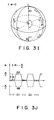
- Fig. 3A shows the waveform of a pulse current to be supplied to the central portion of the semiconductor laser 1 through the driver 2.
- a laser oscillation frequency of 2.5 GHz is modulated into alternate positive and negative pulses, each having the width ⁇ . If this modulated signal is expressed as the phase of a center oscillation frequency, switching occurs between 0 and ⁇ /2 every ⁇ /2, as shown in Fig. 3C.
- the above-mentioned ideal pulse waveform is assumed in the following description.
- the gist of this embodiment is that the phase of output light is switched between 0 and ⁇ /2 within a period of time shorter than ⁇ /2. Therefore, the present invention is not limited to the above-mentioned modulated waveforms of the current and oscillation frequency.
- the driver 2 is adjusted such that the phase of output light is changed between 0 and ⁇ /2 within a short period of time every ⁇ /2, as shown in Fig. 3C.
- the light electric field of the output light at this time can be expressed as
- the time-averaged laser oscillation spectrum line width is increased.
- This increase causes phase discontinuity of a beat signal, over time, when beating is caused between different monochromatic light components having similar frequencies and predetermined polarization states and phases. That is, in general, the phase of a beat signal as well as its amplitude vary from time slot (1) to time slot (2).
- the phase variation of the beat signal is dependent on the polarization states of different monochromatic light components. If ⁇ is prolonged, a phase variation per unit time in a transient portion is reduced, and the average spectrum line width is increased. If ⁇ is shortened, the phase variation becomes steep, the spectrum line width is reduced but a sideband is produced at a remote position.
- the speed of direct modulation of the semiconductor laser can be easily increased as compared with a case wherein an external phase modulator is used.
- the polarization switching light source requires only a small driving current of several mA for a switching operation, and hence the load of the driver is small as compared with a high-speed external phase modulator requiring a driving voltage of several V or more.
- Fig. 4 shows a module equivalent to the polarization switching light source in Fig. 1.
- a semiconductor laser 1, a lens 3, and an optical isolator 4 are housed in a module 41 together with a Peltier element.
- the semiconductor laser 1 is basically the same as that shown in Fig. 2A.
- Output light from the optical isolator 4 is coupled with polarization matching to the input fiber of a 1 : 1 polarization maintaining fiber coupler 45 through a spherical lens 42.
- Each output of the fiber coupler 45 is connected to one end of each of two polarization maintaining optical fibers 43 (optical path A) and 44 (optical path B).
- each of the polarization maintaining optical fibers 43 and 44 is connected to a fiber-optic polarization beam splitter (working as a coupler) 48 such that the polarization main axes are perpendicular to each other.
- the fiber-optic polarization beam splitter 48 is designed to transfer almost 100% of the light polarized in x axis from one optical fiber to the other optical fiber and to leave almost 100% of the light polarized in y axis from the other optical fiber in the same optical fiber. Therefore, light components propagating through the two polarization maintaining optical fibers 43 and 44 are output from a single fiber 49.
- the value of ⁇ 1 is 10 cm, provided that an equivalent refractive index n eff of an optical fiber is 1.5.
- the modulation method, operation, and effect of the semiconductor laser 1 are the same as those in the previous embodiment.
- the range of components to be formed into a module is not limited to that described above.
- the range may include the fiber couplers 45 and 48 and the optical fibers 43, 44, and 49.
- the optical fibers may be integrated with the module in the form of a pigtail.
- the fiber-optic polarization beam splitter need not be used to synthesize two branch light components.
- a 10 : 1 polarization beam splitter or a normal polarization-independent optical coupler may be used. In this case, feedback control of polarization switching can be performed by using the other fiber output light.
- the semiconductor laser 1 is not limited to the one shown in Fig.
- semiconductor lasers e.g., a DBR laser, an external resonator laser, a double-hetero laser, and a strained quantum well laser
- a material for a semiconductor laser various combinations of substances, such as GaAs/AlGaAs, GaAs/InGaAlP, and GaSb/GaAlSb, can be used. Therefore, the apparatus can be applied to various types of light, e.g., visible light and infrared light.
- modulation methods are available as modulation methods of performing polarization switching with the arrangement of the polarization switching light source of the present invention.
- Fig. 5A shows the modulation waveform for an oscillation frequency.
- the phase of local oscillation light is changed by ⁇ before and after the application of the pulse. Since a branch light component propagating through the optical fiber 44 is delayed by ⁇ /2 in the optical system, phases ⁇ A (t) and ⁇ B (t) of light electric fields synthesized by the fiber optic polarization beam splitter (working as a coupler) 48 appear as shown in Fig. 5B, similar to the above-described case.
- 5C shows changes in polarization state on a PLQR circular cross section of the Poincaré sphere, although the polarization states in time slots (1) and (3) are the same, the phase is changed by ⁇ , i.e., inverted. Similarly, the polarization states in time slots (2) and (4) are the same, but the phase is inverted. This modulation method is different from that described above in this regard.
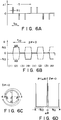
- Figs. 6A to 6D Three modulation methods which satisfy the conditions will be described below with reference to Figs. 6A to 6D, Figs. 7A to 7C, and Figs. 8A to 8C, respectively.
- Figs. 6A, 7A, and 8A respectively show laser modulation current waveforms.
- Figs. 6B, 7B, and 8B respectively show phases ⁇ A (t) and ⁇ B (t) of light electric fields synthesized by the fiber-optic polarization beam splitter 48.
- Figs. 6A, 7A, and 8A respectively show laser modulation current waveforms.
- Figs. 6B, 7B, and 8B respectively show phases ⁇ A (t) and ⁇ B (t) of light electric fields synthesized by the fiber-optic polarization beam splitter 48.
- 6C, 7C, and 8C respectively show changes in polarization state on a PLQR circular cross section of the Poincaré sphere.
- ⁇ 0 is assumed.
- polarization switching can be realized even if ⁇ ⁇ 0.
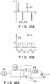
- Figs. 9A and 9B show a case wherein three or more polarization states are switched. In this case, phase modulation of 2/3 ⁇ is performed with one pulse.
- the propagation delay between the two optical paths is not limited to ⁇ /2.
- Figs. 10A and 10B show a case wherein the propagation delay is set to be ⁇ /4.
- Figs. 9A and 10A respectively show laser modulation current waveforms.
- Figs. 9B and 10B respectively show phases ⁇ A (t) and ⁇ B (t) of light electric fields synthesized by the polarization beam splitter 48.
- various modifications of the modulation method can be made.
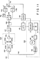
- Fig. 11 shows the arrangement of a heterodyne optical receiver of a 100 Mb/s FSK single filter detection scheme.
- a polarization switching light source 100 as a local oscillation source has an arrangement substantially the same as that shown in Fig. 4.
- Output light from the local oscillation source 100 is input to a 1 : 1 optical coupler 102 through an optical fiber 49.
- Reception signal light is input to the 1 : 1 optical coupler 102 through an optical fiber 101.
- the output light from the local oscillation source 100 and the signal light are mixed with each other at a ratio of 1 to 1 and are heterodyne-received by a balanced optical receiver 104 through optical fibers 103a and 103b.
- the optical coupler 102 serves as a 180° hybrid circuit.
- the balanced optical receiver 104 comprises a light receiving portion constituted by a series circuit of two photodiodes 105a and 105b, and an intermediate frequency (IF) band front-end amplifier 106 for receiving an output from a node between outputs from the photodiodes 105a and 105b.
- the following components are connected to the output of the IF amplifier 106: a bandpass filter 107, a mixer 108, a signal branch circuit 109, a ⁇ /2-delay circuit 110, a low-pass filter 111, and an analog adder 112.
- Part of the output of the bandpass filter 107 is coupled to an IF automatic frequency control (AFC) circuit 113.
- the AFC circuit 113 maintains an IF frequency constant by controlling a current to a semiconductor laser 41 in the local oscillation source 100 through a laser driver 2.
- Polarization switching is realized by the modulation method shown in Figs. 3A to 3L.
- a polarization coordinate system OXY of the optical coupler 102 corresponds to that of the polarization switching light source in Figs. 3A to 3L.
- an x component E Lx and a y component E Ly of an electric field strength E L of the local oscillation light are respectively given by
- An x component E Sx and a y component E Sy of the photoelectric field strength ES of the signal light input from the optical fiber 101 to the optical coupler 102 are respectively given by
- the photodiode 105 does not respond to a light electric field of ⁇ S + ⁇ L . In addition, the x and y components of an electric field do not interfere with each other. Since the optical coupler 102 serves as a 180° hybrid circuit, the in-phase components of output currents from the photodiodes 105a and 105b are removed (balanced optical receiver).
- the output v IF is then subjected to square-law detection in the mixer 108 and is branched by the signal branch circuit 109 on the basis of the value of f(t).
- the circuit 109 is connected to the ⁇ /2 delay circuit 110. If each branch component is filtered by the low-pass filter 111, the following detection output can be obtained:
- v0 ⁇ PA2
- the cutoff frequencies of the low-pass filter is set to be 400 MHz, an intermediate value between 200 MHz (1/T S ) and 1 GHz ( ⁇ IF1 /2 ⁇ ).
- v0 PA2
- the power penalty caused by detecting only a signal component having one polarization state in each sub-time frame is 3 dB.
- the signal value S 0, since the bandpass filter output becomes 0, the output from the adder 112 becomes 0.
- the apparatus of the present invention can achieve a reduction in cost by forming it into an IC. Therefore, the cost of the apparatus can be greatly reduced as compared with the case wherein the polarization diversity module is used.
- the apparatus of the present invention is suitable for mass production.
- pulse-like frequency modulation accompanying polarization switching is caused in a beat output.
- the signal branch circuit 109 is designed not to pass a signal during a switching operation.
- Such an operation can be realized by, e.g., adjusting the duty of a gate pulse output from a clock control circuit 114.
- a penalty is caused in accordance with a reduction in reception energy due to a signal, a stable operation can be realized.
- the time required for switching, including pulse jitter is about 250 ps.
- the penalty based on the fact that signal power corresponding to this portion cannot be used is 0.4 dB or less.
- the AFC circuit 113 is controlled by a gate signal output from the clock control circuit 114 to be operated only when the output signal is "1".
- the duty of a gate pulse output from the clock control circuit 114 is adjusted to prevent a frequency variation in polarization switching from causing an unstable AFC operation.
- the time slot T is divided into two portions. However, the time slot T may be divided into three or more portions. If the time slot is divided into six or more portions, polarization switching can be regarded as polarization scrambling, and the components from the signal branch circuit 109 to the adder 112 can be replaced with one low-pass filter. More specifically, by setting the time constant of the low-pass filter to be a value between the length of the sub-time slot T S and that of the time slot T, averaging, i.e., addition, of the respective sub-time slots can be performed.
- FSK is performed.
- the present invention can be applied to other modulation methods, such as DPSK and ASK, and other detection methods, such as delay detection.
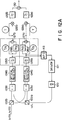
- Fig. 12A shows the arrangement of a polarization diversity heterodyne optical receiver of a 200 Mb/s DPSK differential detection scheme of an embodiment according to the third aspect of the present invention.
- This optical receiver is designed to selectively receive signals, of light signals subjected to optical FDM at intervals of 2.5 GHz, which are transmitted through a fiber.
- This operation can be realized by performing pulse-like direct frequency modulation in the boundary between adjacent sub-time slots by using a laser driver 121 according to equation (2).
- the time required for phase switching is 0.1 ns.
- Local oscillation light is incident on a polarization beam splitter 122a at an angle of 45° with respect to its optical axis to be split into two components having the same power.
- signal light is split into two polarized light components by a polarization beam splitter 122b.
- the signal light components and the local oscillation light components are respectively mixed by fiber couplers 123a and 123b while their polarization states are matched with each other.
- the mixed light components are respectively received by balanced optical receivers 124a and 124b.
- the arrangement of each light receiver is substantially the same as that of the optical receiver of the second embodiment.
- An output from each of bandpass filters 125a and 125b connected to the outputs of the respective optical receiving units is divided into two branch outputs.
- One branch output is delayed with respect to the other branch output by T/5, while the phase of the other branch output is delayed by 90° by a 90° phase shifter 126a or 126b.
- one branch output and the other branch output are added by an adder 127a or 127b.
- An output from each of the adders 127a and 127b is divided into two portions. After one branch output is delayed by T, the two outputs are multiplied with each other by a mixer 128a or 128b. The resulting value is then introduced into a low-pass filter 129a or 129b.
- each bandpass filter 125a or 125b is coupled to an IF automatic frequency control (AFC) circuit 113.
- the AFC circuit 113 controls the oscillation frequency of the local oscillation light source 120 through the laser driver 121 so as to keep an IF frequency constant.
- Signal light includes a plurality of channels.
- a component having an angular frequency ⁇ S1 to be received and a component having an angular frequency ⁇ S2 in a channel adjacent to the opposite side of local oscillation light having an angular frequency ⁇ L will be considered.
- Other components need not be considered because beating occurs outside the band of each light receiving unit.
- An output from the local oscillation source 120 is phase-modulated by ⁇ /2 four times in the time slot T by the laser driver 121.
- the polarization beam splitter 122a or 122b, the fiber coupler 123a or 123b, and the balanced optical receiving unit 124a or 124b receive beat signals produced by the respective polarized light components of the local oscillation light and the signal light in each sub-time slot.
- the phase of the received beat signal is shifted by ⁇ /2 for every sub-time slot.
- This beat output is divided into two branch beat outputs.
- One branch beat output is then delayed with respect to the other branch beat output by T/5, while the phase of the other branch beat output is shifted by ⁇ /2 by the phase shifter 126a.
- the two outputs are added by the adder 127a.
- Adder outputs X1 are given by
- the optical system can be greatly simplified as compared with the polarization diversity image rejection light receiver shown in Fig. 18.
- an electronic circuit allows a great reduction in labor and cost. Therefore, a considerable reduction in cost can be achieved as a whole.
- the performance of the apparatus can be improved in terms of temperature characteristics and stability of operation. Signals corresponding to portions of the switching time and AFC can be treated in the same manner as in the second embodiment.
- Fig. 12B shows a case wherein phase switching of the local oscillation source is alternately performed between ⁇ /2 and - ⁇ /2.
- the basic arrangement of the local oscillation source is similar to that shown in Fig. 12A, the portions enclosed within an alternate long and short dashed line in Fig. 12A is replaced with the portion shown Fig. 12B.
- TS 1.25 ns
- the IF frequency is 800 MHz.
- Signal switching circuits 131a and 131b are respectively arranged in front of the phase shifters 126a and 126b. Under the same conditions as in the above-described embodiment, the following outputs appear at the output of the optical receiving unit in each sub-time slot of the branch component of the polarised light a :
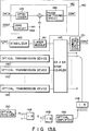
- Fig. 13A shows the schematic arrangement of an optical FDM high-definition CATV distribution system according to this embodiment.
- 200-Mb/s DPSK signals are transmitted in 64 channels at channel intervals of 6 GHz.
- the wavelength band used in this system is about 30 ⁇ .
- Each light transmitter 140 includes a semiconductor laser module 141, a driver 142, and a stabilizing circuit 143.
- the driver 142 includes a bias circuit 144, a DPSK coder 145, a phase switching circuit 146, and the like.
- Light signals of the respective channels are mixed with each other by a star coupler 147 and are distributed to tens of thousands of subscriber's optical receivers 150 through 1 : 8 light distributors 148 and optical amplifiers 149 for compensating for losses accompanying the distribution. Synchronization of modulation timings, the channel interval, and the absolute frequency are controlled by a common control system 151.
- Fig. 13B shows the arrangement of each subscriber's optical receiver.
- the arrangements of a polarization switching local oscillation source 152, a photo-coupler 153, and a balanced optical receiving unit 154 are the same as those in the optical receiver of the second embodiment.
- An output from the balanced optical receiving unit 154 is differentially detected by a differential detector 155.
- the detection output is converted into a digital value by an A/D converter 156 and is input to four sample/hold circuits 157 having different sampling timings. Outputs from these circuits 157 are then added by a sample/hold circuit 158 arranged after the circuits 157.
- the addition result is output to an identifying circuit 159.
- the optical receiver 150 includes a clock circuit 160 for controlling the timings of the sample/hold circuits and an AFC circuit 161 for stabilizing the oscillation frequency of a local oscillation source.
- the optical transmitter 140 performs 0- or ⁇ -phase pulse modulation of a semiconductor laser through the DPSK coder 145.
- the time slot is divided into two phase time slots T1 and T2.
- This phase modulation is performed by decreasing the optical frequency in the form of a pulse.
- the timings of this modulation are controlled by a common control system 151 so as to coincide with each other in all the channels when light signals are mixed by the star coupler 147. Therefore, in the subscriber's optical receivers 150, frequency variations accompanying phase modulation simultaneously occur in the respective channels.
- a signal value in a given time slot j of a channel i is represented by A ij (1 or -1)
- the electric field strengths of light outputs in the time slots T1 and T2 are respectively represented by A ij
- Output light from the local oscillation source 152 of the light receiver 150 alternately exhibits orthogonal polarization states upon polarization switching.
- These polarization states respectively define polarization sub-time slots T A and T B .
- the polarization sub-time slots are set to be switched at an intermediate position in a phase sub-time slot.
- phase modulation for polarization switching is realized by decreasing the optical frequency of the local oscillation source 152 in the form of a pulse by using the modulation method shown in Figs. 5a to 5C. Therefore, when the output light exhibits the same polarization state again, the phase is inverted.
- a polarization sub-time slot A output light exhibiting a polarization state A with an electric field strength
- a polarization sub-time slot B output light exhibiting a polarization state B with an electric field strength
- This local oscillation light is mixed with the signal light by the optical coupler 153, and the resulting light is received by the balanced optical receiver 154.
- the following beat output components appear:
- the sign "-" is produced when the phase is inverted by 180x when the polarization switching shown in Figs. 5A to 5C is performed.
- These outputs are converted into positive/negative octonary values by the A/D converter 156.
- the input level of the A/D converter 156 can be kept constant by controlling the gain of the amplifier of the balanced light receiving unit 154. Since these outputs appear time-serially in the order named, they are held by the sample/hold circuits 157 having different sampling timings until the last output X ij2A appears. When the last output X ij2A appears, all the outputs are input to the sample/hold circuit 158 to be added. As a result, the following value is obtained by the identifying circuit 159:
- the clock circuit 160 performs clock extraction on the basis of the frequency variation of an output signal from the balanced optical receiver 154. That is, since a high-frequency beat component accompanying a frequency variation appears upon switching of sub-time slots, clock extraction can be performed on the basis of the timing that the beat component appears. Since a frequency variation changes depending on the value of a DPSK signal upon switching of time slots, the frequency variations of local oscillation light and signal light can be identified. Furthermore, by detecting the interval between the frequency variation of signal light and that of local oscillation light, the timing of polarization switching can be controlled.
- an error accompanying a switching operation can be prevented by performing timing control to inhibit an operation of the A/D converter 156 at the instant when a beat frequency variation accompanying the phase variation of signal light or local oscillation light appears.
- the frequency variation of the local oscillation source can be suppressed by inhibiting the use of a beat signal in a switching state for AFC of the local oscillation source. Since the timings of phase switching are the same in all the channels, no error is caused in a given channel due to the influences of a frequency variation in another channel.
- the coherent transmission system of this embodiment with one optical receiving unit, the same function as that of a polarization/phase-diversity light receiver using four optical receiving units can be achieved.
- the operation speed of the optical receiver is increased, since a high intermediate frequency need not be used because of phase switching, no significant problems are posed.
- the system requires a complicated electronic circuit.
- an increase in cost can be suppressed by the use of ICs. Therefore, the complicated optical system can be simplified, and the number of optical receiving units can be reduced. Such merits are much worthier than the above-mentioned demerits.
- the characteristics of the respective optical receiving units In multi-port reception, the characteristics of the respective optical receiving units must be matched with each other.
- the present invention is not limited to this embodiment but can be applied to, e.g., an optical subscriber's system, a trunk transmission system, an optical LAN, a MAN, and an optical switching system.
- An optical FDM high-definition CATV distribution system has substantially the same arrangement as that of the system shown in Fig. 13A.
- 150-Mb/s DPSK signals are transmitted in 64 channels at channel intervals of 4.5 GHz in a wavelength band of 1.55 ⁇ m.
- the arrangement of each light transmitter 140 is the same as that in the fourth embodiment except that five phase sub-time slots are present, and the phase changes by ⁇ /2.
- frequency modulation for DPSK is performed upon switching of time slots, no phase switching is performed.
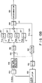
- Fig. 14 shows the arrangement of a subscriber's optical receiver 201.
- the arrangements of a polarization switching local oscillation source 202, an optical coupler 203, a balanced optical receiving unit 204, and the like are the same as those in the light receiver of the fourth embodiment.
- Polarization switching is performed at a frequency twice that used in the fourth embodiment in synchronism with each phase sub-time slot of signal light by the method described with reference to Figs. 3A to 3F. Therefore, a total of 10 phase/polarization sub-time slots are formed.
- signal light includes a plurality of channels, only a component having an angular frequency ⁇ S1 to be received, and a component having an angular frequency ⁇ S2 in a channel adjacent to the opposite side of local oscillation light having an angular frequency ⁇ L will be considered hereinafter.
- Other components need not be considered because beating occurs outside the band of the optical receiving unit.
- the IF frequency of a signal is synchronized with the switching frequency (1.5 GHz) for the sub-time slots. Beat signals resulting from the respective polarization components of local oscillation light and signal light are received in units of sub-time slots. The beat outputs in the respective sub-time slots are
- Part of the output of the bandpass filter 205 is coupled to an IF automatic frequency control (AFC) circuit 213.
- the AFC circuit 213 controls the oscillation frequency of a local oscillation light source 202 through a laser driver so as to keep the IF frequency constant.
- image removing signal reception can be realized independently of polarization with a simple optical system, thus realizing an optical FDM with a reduced channel interval.
- Phase switching may be alternately performed between ⁇ /2 and - ⁇ /2.
- this embodiment employs four phase sub-time slots and eight polarization time slots and eight polarization/phase sub-time slots.
- a signal switching circuit 214 is arranged before the phase shifter 206. Under the same conditions as those in the above-described embodiment, the following outputs appear at the output of the light receiver in the respective subtime slots:
- phase switching method the modulation method for polarization switching, and the combination thereof can be variously modified and applied.
- the polarization switching light source according to the first aspect of the present invention employs direction modulation of a semiconductor laser as a light source, the insertion loss and the number of portions to be adjusted can be reduced as compared with the case wherein an external modulator is used. Therefore, mass production, a cost reduction, and reductions in size and weight of the system can be achieved.
- an external modulator either a phase modulator or a polarization modulator, based on the electrooptic effect requires a high driving voltage, leading to difficulty in high-speed switching.
- phase modulation of ⁇ /2 or ⁇ can be performed with a current pulse of several mA and about 100 ps. Therefore, high-speed switching can be easily achieved.
- the reliability of switching is high because an external modulator having poor temperature characteristics and low reliability is not used, and a semiconductor laser for a light source is generally stabilized against temperature changes and has high reliability.
- the oscillation frequency and output of the laser are kept constant except for a region corresponding to a short period of time during which a pulse current is supplied. Therefore, changes in the oscillation frequency and output of the laser before and after switching, which pose the problems in the conventional polarization switching, do not occur. Therefore, the application range of the system is wide.
- the arrangement of the optical receiver according to the second aspect of the present invention is simpler than that of the conventional polarization diversity optical receiver, thereby allowing a reduction in the number of portions to be assembled and adjusted, and realizing mass production and reductions in cost, size, and weight.
- the reliability can be improved.
- the characteristics of the respective ports must be matched with each other.
- no characteristic variation basically occur in reception of different polarization states.
- the light receiver of the present invention realizes high-speed switching, a low loss, high stability, a low cost, and reductions in size and weight.
- the optical receiver is advantageous in terms of reliability and mass production. Moreover, since no frequency variation of local oscillation light occur before and after polarization switching, the AFC circuit is free from complication. In performing FSK, the IF band and the modulation factor need not be increased exceedingly.
- the arrangement of the optical receiver according to the third and fourth aspects of the present invention is simpler than that of the conventional image rejection optical receiver. Therefore, the number of portions to be assembled and adjusted can be reduced, and mass production and reductions in cost, size, and weight can be realized in addition to an improvement in reliability. Furthermore, in the conventional multi-port reception, the characteristics of the respective ports must be matched with each other. In the method of the present invention, however, since one receiver is used time-divisionally, no characteristic variation basically occur in reception of different branch light components.
- the coherent optical transmission system according to the fifth aspect of the present invention has a simple arrangement as compared with the coherent optical transmission system using the conventional polarization/phase diversity optical receiver.
- the coherent optical transmission systems according to the sixth and seventh aspects of the present invention have simple arrangements as compared with the conventional coherent optical transmission system using the image rejection optical receiver.
- the number of portions to be assembled and adjusted can be reduced, and mass production and reductions in cost, size, and weight can be realized.
- the characteristics of the respective ports must be matched with each other. In the method of the present invention, however, since one receiver is used time-divisionally, no characteristic variation basically occur in reception of different polarization states and different phase states.
- the present invention therefore, (1) a polarization switching light source having a simple arrangement and a small number of limitations can be realized, (2) image rejection signal reception based on new concepts, which prevents complication of an optical system, can be realized, and (3) coherent optical reception with a simple optical system, which is independent from polarization and resistant to phase noise, can be achieved. Therefore, the present invention can solve the problems of polarization matching, phase noise, receiver band width, and high-density optical FDM, which interfere with the practical applications and spread of coherent optical communication, at low cost.
Landscapes
- Physics & Mathematics (AREA)
- Electromagnetism (AREA)
- Engineering & Computer Science (AREA)
- Computer Networks & Wireless Communication (AREA)
- Signal Processing (AREA)
- Optical Communication System (AREA)
- Mechanical Light Control Or Optical Switches (AREA)
- Light Guides In General And Applications Therefor (AREA)
Applications Claiming Priority (2)
| Application Number | Priority Date | Filing Date | Title |
|---|---|---|---|
| JP226531/90 | 1990-08-30 | ||
| JP2226531A JP3001943B2 (ja) | 1990-08-30 | 1990-08-30 | 偏波スイッチング光源、光受信装置及びコヒーレント光伝送システム |
Publications (3)
| Publication Number | Publication Date |
|---|---|
| EP0475640A2 true EP0475640A2 (fr) | 1992-03-18 |
| EP0475640A3 EP0475640A3 (en) | 1992-10-21 |
| EP0475640B1 EP0475640B1 (fr) | 1997-01-08 |
Family
ID=16846599
Family Applications (1)
| Application Number | Title | Priority Date | Filing Date |
|---|---|---|---|
| EP91307937A Expired - Lifetime EP0475640B1 (fr) | 1990-08-30 | 1991-08-30 | Source optique pour la commutation de polarisation, récepteur optique et système de transmission optique cohérent |
Country Status (4)
| Country | Link |
|---|---|
| US (1) | US5247382A (fr) |
| EP (1) | EP0475640B1 (fr) |
| JP (1) | JP3001943B2 (fr) |
| DE (1) | DE69124036T2 (fr) |
Cited By (4)
| Publication number | Priority date | Publication date | Assignee | Title |
|---|---|---|---|---|
| US5299047A (en) * | 1992-04-02 | 1994-03-29 | At&T Bell Laboratories | Ternary data communication using multiple polarizations |
| EP0570151A3 (en) * | 1992-05-08 | 1994-08-17 | Kokusai Denshin Denwa Co Ltd | Optical transmitter with the signal light of reduced degree of polarization and optical depolarizing circuit |
| WO2003096584A1 (fr) * | 2002-05-10 | 2003-11-20 | Siemens Aktiengesellschaft | Procede et dispositif pour limiter la degradation de signal d'un signal multiplexe en polarisation optique |
| WO2004099848A1 (fr) * | 2003-05-08 | 2004-11-18 | Fujitsu Limited | Compensateur de pente de dispersion |
Families Citing this family (36)
| Publication number | Priority date | Publication date | Assignee | Title |
|---|---|---|---|---|
| NL9100292A (nl) * | 1991-02-19 | 1992-09-16 | Nederland Ptt | Optisch zend- en ontvangsysteem met optische circulator. |
| GB2260046B (en) * | 1991-09-26 | 1995-02-15 | Northern Telecom Ltd | Optical communications systems |
| US5432629A (en) * | 1992-01-17 | 1995-07-11 | Nec Corporation | Light transmission device capable of stably transmitting a modulated output light beam |
| GB2264834A (en) * | 1992-02-25 | 1993-09-08 | Northern Telecom Ltd | Optical transmission system |
| JPH0688982A (ja) * | 1992-05-29 | 1994-03-29 | Nec Corp | 光ファイバを用いる光情報記憶装置 |
| JPH06224882A (ja) * | 1992-10-03 | 1994-08-12 | Canon Inc | 光fsk受信器及びそれを用いた光fdm−fsk伝送システム |
| JP3226067B2 (ja) * | 1992-10-03 | 2001-11-05 | キヤノン株式会社 | 光通信方法及び光通信システム |
| US5359678A (en) * | 1993-06-18 | 1994-10-25 | At&T Bell Laboratories | Apparatus and method employing fast polarization modulation to reduce effects of polarization hole burning and/or polarization dependent loss |
| US5327511A (en) * | 1993-06-18 | 1994-07-05 | At&T Bell Laboratories | Apparatus and method employing fast polarization modulation to reduce effects of polarization hole burning and polarization dependent loss |
| US5388170A (en) * | 1993-11-22 | 1995-02-07 | At&T Corp. | Electrooptic device structure and method for reducing thermal effects in optical waveguide modulators |
| JPH07318986A (ja) * | 1994-05-25 | 1995-12-08 | Nec Corp | 導波路型光スイッチ |
| US5717708A (en) * | 1995-11-09 | 1998-02-10 | Mells; Bradley | Method and apparatus of stabilizing a semiconductor laser |
| US5907421A (en) * | 1996-03-20 | 1999-05-25 | The Trustees Of Princeton University | Apparatus for spectral encoding and decoding of femtosecond optical pulses |
| US5812615A (en) * | 1996-12-16 | 1998-09-22 | Motorola, Inc. | Apparatus and method for maximizing frequency offset tracking performance in a digital receiver |
| JPH10239539A (ja) * | 1997-02-24 | 1998-09-11 | Fujitsu Ltd | 光分岐装置及び光分岐出力制御方法 |
| JP3939003B2 (ja) * | 1998-02-20 | 2007-06-27 | 富士通株式会社 | 同期偏波スクランブラを用いた光通信システム及び光受信装置 |
| JP2000121855A (ja) * | 1998-10-21 | 2000-04-28 | Nippon Telegr & Teleph Corp <Ntt> | 直交偏波出力装置 |
| EP0959571B1 (fr) * | 1998-10-22 | 2001-08-29 | Contraves Space AG | Dispositif pour la réception homodyne de signaux optiques modulés par déplacement de phase |
| JP3631025B2 (ja) * | 1998-12-24 | 2005-03-23 | アンリツ株式会社 | 波長分散測定装置及び偏波分散測定装置 |
| US6649898B1 (en) * | 2000-06-30 | 2003-11-18 | Intel Corporation | Method and apparatus for optically enabling a circuit component in a large scale integrated circuit |
| JP2003133638A (ja) * | 2001-08-14 | 2003-05-09 | Furukawa Electric Co Ltd:The | 分布帰還型半導体レーザ素子及びレーザモジュール |
| JP2003060576A (ja) * | 2001-08-22 | 2003-02-28 | Nec Corp | 偏波スクランブラユニット及びこれを用いた多中継伝送システム |
| US20040208646A1 (en) * | 2002-01-18 | 2004-10-21 | Seemant Choudhary | System and method for multi-level phase modulated communication |
| US7019882B1 (en) | 2002-03-21 | 2006-03-28 | Lockheed Martin Corporation | Generation of M-ary digital signaling constellations directly at lightwave frequencies |
| JP4683815B2 (ja) * | 2002-08-27 | 2011-05-18 | 富士通オプティカルコンポーネンツ株式会社 | 偏波スクランブラの制御方法及び駆動回路 |
| EP1566002B1 (fr) * | 2002-11-29 | 2007-02-28 | Pirelli & C. S.p.A. | Systeme de communication optique |
| US7844186B2 (en) * | 2004-02-20 | 2010-11-30 | Alcatel-Lucent Usa Inc. | Method and apparatus for optical transmission |
| JP4687262B2 (ja) * | 2005-06-10 | 2011-05-25 | 日本電気株式会社 | 光送信システムおよび光送信方法 |
| GB2430122B (en) * | 2005-09-09 | 2008-07-09 | Toshiba Res Europ Ltd | A quantum communication system |
| US7406269B2 (en) * | 2006-03-10 | 2008-07-29 | Discovery Semiconductors, Inc. | Feedback-controlled coherent optical receiver with electrical compensation/equalization |
| US7809284B2 (en) * | 2006-06-23 | 2010-10-05 | Alcatel-Lucent Usa Inc. | System and method for receiving coherent, polarization-multiplexed optical signals |
| JP5034770B2 (ja) * | 2007-08-16 | 2012-09-26 | 富士通株式会社 | コヒーレント光受信器および光通信システム |
| JP5736837B2 (ja) | 2011-02-23 | 2015-06-17 | 富士通株式会社 | 光受信装置 |
| US20180188456A1 (en) | 2015-07-09 | 2018-07-05 | Nec Corporation | Pluggable optical module and optical communication system |
| US10122471B2 (en) * | 2016-07-07 | 2018-11-06 | Lockheed Martin Corporation | Spatially dephasing local oscillator for coherent free-space optical communications |
| US10680717B2 (en) * | 2018-06-08 | 2020-06-09 | Maxim Integrated Products, Inc. | Systems and methods for polarization control using blind source separation |
Family Cites Families (8)
| Publication number | Priority date | Publication date | Assignee | Title |
|---|---|---|---|---|
| JPS6352530A (ja) * | 1986-08-22 | 1988-03-05 | Fujitsu Ltd | コヒ−レント光通信用の受信器 |
| US4718120A (en) * | 1986-11-24 | 1988-01-05 | American Telephone And Telegraph Company, At&T Bell Laboratories | Polarization insensitive coherent lightwave detector |
| GB8630959D0 (en) * | 1986-12-29 | 1987-02-04 | British Telecomm | Optical polarisation control |
| GB2213026A (en) * | 1987-11-30 | 1989-08-02 | Plessey Co Plc | Control arrangement for a phase shift keying system |
| US5008958A (en) * | 1988-01-19 | 1991-04-16 | At&T Bell Laboratories | Polarization-insensitive technique for coherent optical communication |
| JPH063512B2 (ja) * | 1988-02-19 | 1994-01-12 | 富士通株式会社 | コヒーレント光通信用偏波ダイバーシティ光受信装置 |
| WO1989008356A1 (fr) * | 1988-03-04 | 1989-09-08 | Fujitsu Limited | Procede et dispositif de modulation d'un laser a semi-conducteur |
| US5060311A (en) * | 1989-06-06 | 1991-10-22 | Siemens Aktiengesellschaft | Method and apparatus for obtaining phase or polarization insensitive optical heterodyne reception for dpsk or ask-modulated transmission signal |
-
1990
- 1990-08-30 JP JP2226531A patent/JP3001943B2/ja not_active Expired - Fee Related
-
1991
- 1991-08-30 EP EP91307937A patent/EP0475640B1/fr not_active Expired - Lifetime
- 1991-08-30 DE DE69124036T patent/DE69124036T2/de not_active Expired - Fee Related
- 1991-08-30 US US07/753,634 patent/US5247382A/en not_active Expired - Lifetime
Cited By (6)
| Publication number | Priority date | Publication date | Assignee | Title |
|---|---|---|---|---|
| US5299047A (en) * | 1992-04-02 | 1994-03-29 | At&T Bell Laboratories | Ternary data communication using multiple polarizations |
| EP0570151A3 (en) * | 1992-05-08 | 1994-08-17 | Kokusai Denshin Denwa Co Ltd | Optical transmitter with the signal light of reduced degree of polarization and optical depolarizing circuit |
| WO2003096584A1 (fr) * | 2002-05-10 | 2003-11-20 | Siemens Aktiengesellschaft | Procede et dispositif pour limiter la degradation de signal d'un signal multiplexe en polarisation optique |
| US7672589B2 (en) | 2002-05-10 | 2010-03-02 | Nokia Siemens Network Gmbh & Co., Kg | Method and polarization-multiplex system for reducing the signal degradation of an optical polarization-multiplex signal |
| WO2004099848A1 (fr) * | 2003-05-08 | 2004-11-18 | Fujitsu Limited | Compensateur de pente de dispersion |
| US7171076B2 (en) | 2003-05-08 | 2007-01-30 | Fujitsu Limited | Dispersion-slope compensator |
Also Published As
| Publication number | Publication date |
|---|---|
| JP3001943B2 (ja) | 2000-01-24 |
| DE69124036T2 (de) | 1997-06-12 |
| US5247382A (en) | 1993-09-21 |
| JPH04109722A (ja) | 1992-04-10 |
| DE69124036D1 (de) | 1997-02-20 |
| EP0475640B1 (fr) | 1997-01-08 |
| EP0475640A3 (en) | 1992-10-21 |
Similar Documents
| Publication | Publication Date | Title |
|---|---|---|
| EP0475640B1 (fr) | Source optique pour la commutation de polarisation, récepteur optique et système de transmission optique cohérent | |
| US5060312A (en) | Polarization independent coherent lightwave detection arrangement | |
| US5654818A (en) | Polarization independent electro-optic modulator | |
| EP0409260B1 (fr) | Récepteur pour communication optique cohérente | |
| EP0251062B1 (fr) | Récepteur pour signaux optiques doublement symétrique | |
| EP1330054B1 (fr) | Système et méthode de communication de modulation de phase multiniveaux | |
| US4882775A (en) | Demodulation technique for coherence multiplexed optical data transmission system | |
| Chikama et al. | Modulation and demodulation techniques in optical heterodyne PSK transmission systems | |
| US7853157B2 (en) | Systems and methods for the polarization insensitive coherent detection and the polarization division multiplexed transmission of optical communication signals | |
| EP0251748B1 (fr) | Système de transmission optique | |
| US4817206A (en) | Optical-fiber transmission system with polarization modulation and heterodyne coherent detection | |
| EP0247738B1 (fr) | Récepteur optique cohérent à hétérodynage indépendant de la polarisation | |
| EP0619658A2 (fr) | Dispositif pour l'extraction d'une horloge optique et dispositif pour le démultiplexage d'un signal multiplexé par division du temps | |
| JPH04335725A (ja) | 光波系のための直角位相光位相変調器 | |
| EP3075083A1 (fr) | Récepteur optique cohérent indépendant de la polarisation | |
| US5146359A (en) | Double-stage phase-diversity receiver | |
| US20040037560A1 (en) | Method and apparatus of utilizing RF/microwave and optical mixing techniques to select a given band of an optical transmission | |
| Okoshi et al. | Four-port homodyne receiver for optical fibre communications comprising phase and polarisation diversities | |
| CA1308440C (fr) | Methode de communication optique a diversite de polarisation et appareil utilisant cette methode | |
| CA2375773A1 (fr) | Procede et appareil d'utilisation de techniques de melange d'hyperfrequences/rf pour selectionner une bande donnee d'une transmission optique | |
| CN113992274A (zh) | 硅基集成高精度射频信号稳相传输芯片、发送端及系统 | |
| US20030076570A1 (en) | Method, system and apparatus for optically receiving information | |
| EP0260745A1 (fr) | Dispositif de détection optique hétérodyne d'un signal optique et système de transmission optique muni d'un tel dispositif | |
| US5467414A (en) | Device for generating feedback signals to regulate optical monitoring circuits (PLL) | |
| EP0310174B1 (fr) | Dispositif pour la détection optique hétérodyne ou synchrone d'un faisceau de signal optique et récepteur muni d'un pareil dispositif |
Legal Events
| Date | Code | Title | Description |
|---|---|---|---|
| PUAI | Public reference made under article 153(3) epc to a published international application that has entered the european phase |
Free format text: ORIGINAL CODE: 0009012 |
|
| 17P | Request for examination filed |
Effective date: 19910918 |
|
| AK | Designated contracting states |
Kind code of ref document: A2 Designated state(s): DE FR GB |
|
| PUAL | Search report despatched |
Free format text: ORIGINAL CODE: 0009013 |
|
| AK | Designated contracting states |
Kind code of ref document: A3 Designated state(s): DE FR GB |
|
| 17Q | First examination report despatched |
Effective date: 19950202 |
|
| GRAG | Despatch of communication of intention to grant |
Free format text: ORIGINAL CODE: EPIDOS AGRA |
|
| GRAH | Despatch of communication of intention to grant a patent |
Free format text: ORIGINAL CODE: EPIDOS IGRA |
|
| GRAH | Despatch of communication of intention to grant a patent |
Free format text: ORIGINAL CODE: EPIDOS IGRA |
|
| RBV | Designated contracting states (corrected) |
Designated state(s): DE FR |
|
| GRAA | (expected) grant |
Free format text: ORIGINAL CODE: 0009210 |
|
| AK | Designated contracting states |
Kind code of ref document: B1 Designated state(s): DE FR |
|
| REF | Corresponds to: |
Ref document number: 69124036 Country of ref document: DE Date of ref document: 19970220 |
|
| ET | Fr: translation filed | ||
| PGFP | Annual fee paid to national office [announced via postgrant information from national office to epo] |
Ref country code: FR Payment date: 19970811 Year of fee payment: 7 |
|
| PLBE | No opposition filed within time limit |
Free format text: ORIGINAL CODE: 0009261 |
|
| STAA | Information on the status of an ep patent application or granted ep patent |
Free format text: STATUS: NO OPPOSITION FILED WITHIN TIME LIMIT |
|
| 26N | No opposition filed | ||
| PG25 | Lapsed in a contracting state [announced via postgrant information from national office to epo] |
Ref country code: FR Free format text: LAPSE BECAUSE OF NON-PAYMENT OF DUE FEES Effective date: 19990430 |
|
| REG | Reference to a national code |
Ref country code: FR Ref legal event code: ST |
|
| PGFP | Annual fee paid to national office [announced via postgrant information from national office to epo] |
Ref country code: DE Payment date: 20080912 Year of fee payment: 18 |
|
| PG25 | Lapsed in a contracting state [announced via postgrant information from national office to epo] |
Ref country code: DE Free format text: LAPSE BECAUSE OF NON-PAYMENT OF DUE FEES Effective date: 20100302 |