EP0480319B1 - Méchanisme pour produire un mouvement rotatif et linéair d'un corps - Google Patents
Méchanisme pour produire un mouvement rotatif et linéair d'un corps Download PDFInfo
- Publication number
- EP0480319B1 EP0480319B1 EP91116931A EP91116931A EP0480319B1 EP 0480319 B1 EP0480319 B1 EP 0480319B1 EP 91116931 A EP91116931 A EP 91116931A EP 91116931 A EP91116931 A EP 91116931A EP 0480319 B1 EP0480319 B1 EP 0480319B1
- Authority
- EP
- European Patent Office
- Prior art keywords
- gear
- drum
- axis
- rotation
- crank arm
- Prior art date
- Legal status (The legal status is an assumption and is not a legal conclusion. Google has not performed a legal analysis and makes no representation as to the accuracy of the status listed.)
- Expired - Lifetime
Links
- 230000009977 dual effect Effects 0.000 claims description 3
- 230000010355 oscillation Effects 0.000 claims description 2
- 239000003638 chemical reducing agent Substances 0.000 description 2
- 230000000694 effects Effects 0.000 description 1
- 230000005611 electricity Effects 0.000 description 1
Images


Classifications
-
- F—MECHANICAL ENGINEERING; LIGHTING; HEATING; WEAPONS; BLASTING
- F16—ENGINEERING ELEMENTS AND UNITS; GENERAL MEASURES FOR PRODUCING AND MAINTAINING EFFECTIVE FUNCTIONING OF MACHINES OR INSTALLATIONS; THERMAL INSULATION IN GENERAL
- F16H—GEARING
- F16H35/00—Gearings or mechanisms with other special functional features
-
- F—MECHANICAL ENGINEERING; LIGHTING; HEATING; WEAPONS; BLASTING
- F16—ENGINEERING ELEMENTS AND UNITS; GENERAL MEASURES FOR PRODUCING AND MAINTAINING EFFECTIVE FUNCTIONING OF MACHINES OR INSTALLATIONS; THERMAL INSULATION IN GENERAL
- F16H—GEARING
- F16H37/00—Combinations of mechanical gearings, not provided for in groups F16H1/00 - F16H35/00
- F16H37/12—Gearings comprising primarily toothed or friction gearing, links or levers, and cams, or members of at least two of these types
- F16H37/16—Gearings comprising primarily toothed or friction gearing, links or levers, and cams, or members of at least two of these types with a driving or driven member which both rotates or oscillates on its axis and reciprocates
-
- F—MECHANICAL ENGINEERING; LIGHTING; HEATING; WEAPONS; BLASTING
- F16—ENGINEERING ELEMENTS AND UNITS; GENERAL MEASURES FOR PRODUCING AND MAINTAINING EFFECTIVE FUNCTIONING OF MACHINES OR INSTALLATIONS; THERMAL INSULATION IN GENERAL
- F16H—GEARING
- F16H35/00—Gearings or mechanisms with other special functional features
- F16H35/02—Gearings or mechanisms with other special functional features for conveying rotary motion with cyclically varying velocity ratio
-
- Y—GENERAL TAGGING OF NEW TECHNOLOGICAL DEVELOPMENTS; GENERAL TAGGING OF CROSS-SECTIONAL TECHNOLOGIES SPANNING OVER SEVERAL SECTIONS OF THE IPC; TECHNICAL SUBJECTS COVERED BY FORMER USPC CROSS-REFERENCE ART COLLECTIONS [XRACs] AND DIGESTS
- Y10—TECHNICAL SUBJECTS COVERED BY FORMER USPC
- Y10T—TECHNICAL SUBJECTS COVERED BY FORMER US CLASSIFICATION
- Y10T74/00—Machine element or mechanism
- Y10T74/14—Rotary member or shaft indexing, e.g., tool or work turret
- Y10T74/1418—Preselected indexed position
- Y10T74/1424—Sequential
- Y10T74/1447—Velocity control
-
- Y—GENERAL TAGGING OF NEW TECHNOLOGICAL DEVELOPMENTS; GENERAL TAGGING OF CROSS-SECTIONAL TECHNOLOGIES SPANNING OVER SEVERAL SECTIONS OF THE IPC; TECHNICAL SUBJECTS COVERED BY FORMER USPC CROSS-REFERENCE ART COLLECTIONS [XRACs] AND DIGESTS
- Y10—TECHNICAL SUBJECTS COVERED BY FORMER USPC
- Y10T—TECHNICAL SUBJECTS COVERED BY FORMER US CLASSIFICATION
- Y10T74/00—Machine element or mechanism
- Y10T74/14—Rotary member or shaft indexing, e.g., tool or work turret
- Y10T74/1482—Single revolution input effects desired fractional output
-
- Y—GENERAL TAGGING OF NEW TECHNOLOGICAL DEVELOPMENTS; GENERAL TAGGING OF CROSS-SECTIONAL TECHNOLOGIES SPANNING OVER SEVERAL SECTIONS OF THE IPC; TECHNICAL SUBJECTS COVERED BY FORMER USPC CROSS-REFERENCE ART COLLECTIONS [XRACs] AND DIGESTS
- Y10—TECHNICAL SUBJECTS COVERED BY FORMER USPC
- Y10T—TECHNICAL SUBJECTS COVERED BY FORMER US CLASSIFICATION
- Y10T74/00—Machine element or mechanism
- Y10T74/19—Gearing
- Y10T74/19555—Varying speed ratio
Definitions
- This invention relates to an apparatus particularly for rotating and tilting a shaft connected to a hub of a dual drum turret for a tire building machine.
- Two drums are mounted on the hub which is rotatable to oscillate the drums between a first tire fabricating position and a second tire fabricating position for applying first position components to a first drum. Then the drums are oscillated and the second position components including a belt overlay and tread are applied to the tire carcass on the first drum in the second tire fabricating position. At the same time, the first position components are being applied to the second drum in the first tire fabricating position to form a second tire carcass. The first tire carcass is finished and removed from the first drum after which the drums are oscillated and the process repeated.
- the axes of rotation of the drums and the hub are in the same plane so that the hub can be oscillated.
- the hub may also be tilted to avoid contact of the drums with the floor.
- the motion of the drums is accelerated smoothly from zero to a maximum and back to zero again to provide a smooth oscillating movement of the drums.
- Figs 1 through 7 are schematic drawings showing the rotation of the gears and the crank at increments during a complete revolution of the crank with the gear teeth areas which have been engaged being shown in heavy lines.
- Fig 8 is an enlarged plan view of a tire building machine turret embodying the invention.
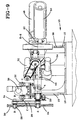
- Fig 9 is an elevation taken along the line 9-9 in Fig 8 with parts being broken away.
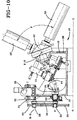
- Fig 10 is an elevation like Fig 9 showing the hub in the tilted position and rotated 90 degrees to place the drums in the intermediate position between the tire fabricating positions.
- a two gear connecting arm and crank apparatus 10 is shown mounted on a tire building machine turret 12 having a base 14.
- a rear portion of the base 14 such as upright rear plate 16 is generally vertical and includes a slide such as vertical linear guide 18.
- a slide member such as bearing block 20 is slidably mounted in the linear guide 18 and rotatably supports a stub shaft 22 being part of the claimed body to be rotated and linearly moved and connected to a main or second gear 24.
- a connecting arm 26 has one end pivotally mounted on the stub shaft 22 at a main gear center A-A and the other end pivotally mounted on a crank shaft 28 supporting a pinion or first gear 30 at a pinion gear center B-B.
- crank shaft 28 is rotatably mounted in a stationary bearing such as pillow block 32 having a crank axis C-C and being mounted on the rear plate 16.
- a crank axis C-C is in substantially the same plane D-D as the linear guide 18 and a crank arm 34 of the crank shaft 28 has a length substantially the same as the effective radius of the pinion gear 30.
- a motor reducer 36 is mounted on the rear plate 16 of the base 14 and is connected to the crank shaft 28 at the crank axis C-C for rotating the crank shaft.
- a front frame member 38 has a ring member 40 pivotally mounted for rotation about a generally horizontal axis E-E.
- the ring member 40 supports a hub member 42 for rotation about an axis of rotation in the ring member.
- a shaft 44 being part of the claimed body to be rotated and linearly moved is mounted on the hub member 42 and extends rearwardly to a universal joint member 46 which may include a slip joint.
- the universal joint member 46 is mounted on the bearing block 20 which is slidably supported in the linear guide 18 of the rear plate 16.
- a first tire building drum 48 and a second tire building drum 50 are rotatably mounted on the hub member 42 with the first tire building drum spaced from the second tire building drum and extending outwardly from the hub member with an axis of rotation at an angle F of about 90 degrees to the axis of rotation of the second tire building drum.
- the first tire building drum 48 and second tire building drum 50 have independent drive means 52 and 54, respectively, to effect rotation of the drums as required.
- Other means for expanding the drums 48 and 50 may also be provided.
- the hub member 42 and shaft 44 are in a generally horizontal position with the crank shaft 28 in the vertical position extending upwardly from the crank axis C-C.
- the first tire building drum 48 is in a first position for application of first tire components on the drum. After application of the first components to provide a first tire carcass, the crank shaft 28 is rotated by the motor reducer 36 with the crank arm 34 moving in a clockwise direction as shown in Figs 2 through 7.
- the second tire building drum 50 with the tire carcass formed by the first position components applied at position J may be returned to the position H shown in Fig 8 by reversing the rotation of the crank shaft 28 and moving the crank arm 34 in a counter clockwise direction from the position shown in Fig 7 to the position shown in Fig 1.
- the tire carcass formed on the second tire building drum 50 can be completed and the first position components applied to the first tire building drum 48 to form a third tire carcass.
- the service lines for air pressure and electricity can be connected directly to the drum mechanism. This is not possible with apparatus where the drums rotate in only one direction to provide different positions of the drums.
Landscapes
- Engineering & Computer Science (AREA)
- General Engineering & Computer Science (AREA)
- Mechanical Engineering (AREA)
- Transmission Devices (AREA)
- Tyre Moulding (AREA)
- Automatic Assembly (AREA)
Claims (9)
- Appareil pour conférer un mouvement rotatif et linéaire à un corps, ledit appareil comprenant un premier engrenage (30) possédant un premier axe au centre du premier engrenage et étant muni d'un arbre d'entraînement (28), un second engrenage (24) prévu sur un arbre (22) pour tourner avec ce dernier autour d'un second axe parallèle audit premier axe au centre du second engrenage et relié en entraînement audit corps, ledit arbre d'entraînement (28) étant relié à un bras de manivelle (34) rotatif dans un palier stationnaire (32) autour d'un axe de bras de manivelle parallèle audit axe du premier engrenage, un bras de liaison (26) monté en pivotement sur ledit arbre d'entraînement (28) et sur ledit second arbre d'engrenage (22), ledit premier engrenage (30) se trouvant en engrènement conjugué avec ledit second engrenage (24), ledit second arbre d'engrenage (22) est emporté par un coulisseau (20) monté en coulissement dans un guide linéaire (18) procuré dans un élément de base stationnaire (14) de l'appareil et dans le même plan que celui dudit axe de manivelle, par lequel, lors de la rotation dudit bras de manivelle (34), ledit premier engrenage (30) tourne en faisant tourner ledit second engrenage (24) et en imprimant audit coulisseau (20) un mouvement alternatif dans ledit guide linéaire par rapport à l'axe dudit bras de manivelle, par lequel on imprime audit corps un mouvement linéaire.
- Appareil selon la revendication 1, dans lequel ledit diamètre dudit premier engrenage est inférieur au diamètre dudit second engrenage, par lequel ledit second engrenage tourne en effectuant moins d'une révolution complète et le centre dudit second engrenage reprend sa position initiale après une révolution dudit bras de manivelle.
- Appareil selon la revendication 2, dans lequel le diamètre dudit premier engrenage représente la moitié du diamètre dudit second engrenage, par lequel ledit second engrenage effectue une rotation de 180 degrés après une révolution dudit premier engrenage et dudit bras de manivelle.
- Appareil selon la revendication 3, dans lequel ledit corps englobe un arbre (44) relié à un moyeu (42) supporté en rotation autour d'un axe de moyeu dans une double tête revolver en tambour (12) d'une machine de confection de bandages pneumatiques, un premier tambour (48) monté en rotation sur ledit moyeu, un second tambour (50) monté en rotation sur ledit moyeu à un endroit espacé dudit premier tambour, l'axe de rotation du second tambour s'étendant vers l'extérieur à partir dudit moyeu, en formant un angle d'environ 90 degrés jusqu'à l'axe de rotation du premier tambour, et l'axe de rotation dudit premier tambour, l'axe de rotation dudit second tambour et l'axe dudit moyeu se trouvant dans le même plan pour procurer un positionnement interchangeable dudit premier tambour et dudit second tambour.
- Appareil selon la revendication 4, dans lequel ladite double tête revolver en tambour (2) englobe, en outre, ledit élément de base (14) possédant une portion frontale et une portion dorsale, ledit moyeu (42) étant supporté en rotation pour effectuer une rotation dans un anneau (40) monté en pivotement à ladite portion frontale pour basculer autour d'un axe généralement horizontal, un joint universel (46) reliant ledit arbre (44) et l'arbre (22) dudit second engrenage muni d'un accouplement extensible destiné à compenser le basculement et la rotation dudit moyen d'arbre lors de la mise en service.
- Appareil selon la revendication 5, dans lequel on monte une plaque dorsale (16) sur ladite portion dorsale, qui englobe ledit guide linéaire (18).
- Appareil selon la revendication 1, englobant un moyen mécanique motorisé pour faire tourner ledit bras de manivelle (34).
- Appareil selon la revendication 1, dans lequel ledit moyen mécanique motorisé englobe un moyen pour faire tourner ledit bras de manivelle à une vitesse de rotation constante, par lequel ladite rotation dudit second engrenage et dudit mouvement vertical oscillant sont soumis à une accélération sans à-coups depuis une valeur zéro jusqu'à une valeur maximale et subissent ensuite une décélération jusqu'à la valeur zéro au cours d'une rotation complète dudit bras de manivelle.
- Appareil selon la revendication 5, dans lequel ledit bras de manivelle (34) tourne en effectuant une révolution complète dans une direction pour faire basculer et tourner ledit moyeu (42) dans une direction et ensuite, ledit bras de manivelle (34) tourne dans une direction opposée pour faire basculer et pour faire tourner ledit moyeu dans une direction opposée pour procurer l'oscillation dudit moyeu, si bien que l'on peut relier directement les branchements destinés au premier tambour (48) et audit second tambour (50), directement aux moyens d'entraînement (52, 54) dudit premier tambour et dudit second tambour.
Applications Claiming Priority (2)
| Application Number | Priority Date | Filing Date | Title |
|---|---|---|---|
| US07/597,193 US5031478A (en) | 1990-10-12 | 1990-10-12 | Two gear, connecting arm and crank apparatus |
| US597193 | 1990-10-12 |
Publications (3)
| Publication Number | Publication Date |
|---|---|
| EP0480319A2 EP0480319A2 (fr) | 1992-04-15 |
| EP0480319A3 EP0480319A3 (en) | 1993-03-10 |
| EP0480319B1 true EP0480319B1 (fr) | 1996-01-31 |
Family
ID=24390484
Family Applications (1)
| Application Number | Title | Priority Date | Filing Date |
|---|---|---|---|
| EP91116931A Expired - Lifetime EP0480319B1 (fr) | 1990-10-12 | 1991-10-04 | Méchanisme pour produire un mouvement rotatif et linéair d'un corps |
Country Status (10)
| Country | Link |
|---|---|
| US (1) | US5031478A (fr) |
| EP (1) | EP0480319B1 (fr) |
| JP (1) | JP3468533B2 (fr) |
| KR (1) | KR0173127B1 (fr) |
| AU (1) | AU641812B2 (fr) |
| BR (1) | BR9104259A (fr) |
| CA (1) | CA2038156C (fr) |
| DE (1) | DE69116789T2 (fr) |
| ES (1) | ES2084745T3 (fr) |
| MX (1) | MX9101410A (fr) |
Families Citing this family (7)
| Publication number | Priority date | Publication date | Assignee | Title |
|---|---|---|---|---|
| CA2034005C (fr) | 1989-06-08 | 1994-07-12 | Yasuo Yoshizawa | Levier a pivot mobile et appareil mecanique comportant leditlevier |
| US5730829A (en) * | 1996-03-26 | 1998-03-24 | The Goodyear Tire & Rubber Company | Two drum turret for tire assembly |
| KR100463266B1 (ko) * | 2002-09-24 | 2004-12-23 | 정봉우 | 글루콘산을 함유하는 양파 음료 조성물 및 그 제조방법 |
| US20090229888A1 (en) * | 2005-08-08 | 2009-09-17 | Shilin Chen | Methods and systems for designing and/or selecting drilling equipment using predictions of rotary drill bit walk |
| JP2013035218A (ja) * | 2011-08-08 | 2013-02-21 | Yokohama Rubber Co Ltd:The | ベルト成形装置及び方法 |
| CN106969121A (zh) * | 2017-04-26 | 2017-07-21 | 上海工程技术大学 | 一种间歇式滑轨拨叉往复圆周运动机构 |
| KR102344090B1 (ko) | 2021-07-29 | 2021-12-29 | 주식회사 찾는사람들 | 전문직 매칭 시스템의 기일 관리 장치 및 방법 |
Family Cites Families (6)
| Publication number | Priority date | Publication date | Assignee | Title |
|---|---|---|---|---|
| DE475705C (de) * | 1929-04-30 | Fr Hesser Maschinenfabrik Akt | Getriebe zur ungleichfoermigen Drehung einer Welle | |
| US2825243A (en) * | 1953-05-18 | 1958-03-04 | Raymond L Wrinkle | Power transmission apparatus |
| US2784612A (en) * | 1955-03-08 | 1957-03-12 | Cleveland Universal Jig Compan | Mechanism for imparting rotary motion to index tables and the like |
| US3473417A (en) * | 1968-03-21 | 1969-10-21 | Ludlum Steel Corp | Two-position intermittent movement |
| US3665789A (en) * | 1970-03-09 | 1972-05-30 | Warner Swasey Co | Turret assembly |
| DE3304171A1 (de) * | 1983-02-08 | 1984-08-09 | Heiss Maschinenbau GmbH & Co Allrobot KG, 8250 Dorfen | Schrittschaltanrieb |
-
1990
- 1990-10-12 US US07/597,193 patent/US5031478A/en not_active Expired - Lifetime
-
1991
- 1991-03-13 CA CA002038156A patent/CA2038156C/fr not_active Expired - Fee Related
- 1991-10-02 BR BR919104259A patent/BR9104259A/pt not_active IP Right Cessation
- 1991-10-02 MX MX9101410A patent/MX9101410A/es unknown
- 1991-10-04 ES ES91116931T patent/ES2084745T3/es not_active Expired - Lifetime
- 1991-10-04 DE DE69116789T patent/DE69116789T2/de not_active Expired - Fee Related
- 1991-10-04 EP EP91116931A patent/EP0480319B1/fr not_active Expired - Lifetime
- 1991-10-11 JP JP29041991A patent/JP3468533B2/ja not_active Expired - Fee Related
- 1991-10-11 AU AU85785/91A patent/AU641812B2/en not_active Ceased
- 1991-10-11 KR KR1019910017913A patent/KR0173127B1/ko not_active Expired - Fee Related
Also Published As
| Publication number | Publication date |
|---|---|
| EP0480319A3 (en) | 1993-03-10 |
| CA2038156A1 (fr) | 1992-04-13 |
| US5031478A (en) | 1991-07-16 |
| DE69116789T2 (de) | 1996-09-19 |
| MX9101410A (es) | 1992-06-01 |
| CA2038156C (fr) | 2001-07-03 |
| BR9104259A (pt) | 1992-06-02 |
| ES2084745T3 (es) | 1996-05-16 |
| AU641812B2 (en) | 1993-09-30 |
| DE69116789D1 (de) | 1996-03-14 |
| JPH04290656A (ja) | 1992-10-15 |
| KR0173127B1 (ko) | 1999-02-18 |
| AU8578591A (en) | 1992-04-16 |
| JP3468533B2 (ja) | 2003-11-17 |
| KR920008385A (ko) | 1992-05-27 |
| EP0480319A2 (fr) | 1992-04-15 |
Similar Documents
| Publication | Publication Date | Title |
|---|---|---|
| EP0142072A2 (fr) | Robot de meulage | |
| US3953942A (en) | Apparatus for grinding inner surface of a vehicle tire | |
| CA2038156C (fr) | Appareil a manivelle et bras de raccordement a deux engrenages | |
| JP2602867B2 (ja) | 移動体の車輪手段 | |
| JPH03196994A (ja) | 判型の大きさに関して調節可能な走行ウエツブ切断装置 | |
| EP0423146A1 (fr) | Pieces de meulage. | |
| US20030060148A1 (en) | High speed centrifugal processor | |
| CA2038138C (fr) | Appareil et methode de construction de pneumatiques | |
| WO2006071059A1 (fr) | Appareil et procede de fabrication de produits de formes variables | |
| JPH0156852B2 (fr) | ||
| JP2880405B2 (ja) | 靴の加工装置 | |
| US1836853A (en) | Machine for forming ovals | |
| JPH06177Y2 (ja) | 管状体屈曲装置 | |
| JP3199411B2 (ja) | 自動切断機の走行装置 | |
| JPS58155160A (ja) | 投影型ならい研削盤 | |
| JPH0530873Y2 (fr) | ||
| JP3094448U (ja) | 傾斜回転テーブルのテーブル回転駆動方式 | |
| JPH0215997A (ja) | タイヤサイド部の切断装置 | |
| JP2544526B2 (ja) | 回転ドラム型走間シャ― | |
| JP2025510155A (ja) | 経路曲線用の容器駆動部 | |
| JPH06143111A (ja) | 研摩装置 | |
| JPS608165B2 (ja) | 内ば歯車の歯面の研削を行うための方法及び装置 | |
| JPH0567441U (ja) | 加工ヘッド駆動機構 | |
| JPH078127Y2 (ja) | 塗膜面の研磨装置 | |
| JPH0465903B2 (fr) |
Legal Events
| Date | Code | Title | Description |
|---|---|---|---|
| PUAI | Public reference made under article 153(3) epc to a published international application that has entered the european phase |
Free format text: ORIGINAL CODE: 0009012 |
|
| 17P | Request for examination filed |
Effective date: 19911004 |
|
| AK | Designated contracting states |
Kind code of ref document: A2 Designated state(s): DE ES FR GB IT LU NL |
|
| PUAL | Search report despatched |
Free format text: ORIGINAL CODE: 0009013 |
|
| AK | Designated contracting states |
Kind code of ref document: A3 Designated state(s): DE ES FR GB IT LU NL |
|
| 17Q | First examination report despatched |
Effective date: 19940819 |
|
| GRAA | (expected) grant |
Free format text: ORIGINAL CODE: 0009210 |
|
| AK | Designated contracting states |
Kind code of ref document: B1 Designated state(s): DE ES FR GB IT LU NL |
|
| REF | Corresponds to: |
Ref document number: 69116789 Country of ref document: DE Date of ref document: 19960314 |
|
| ET | Fr: translation filed | ||
| ITF | It: translation for a ep patent filed | ||
| REG | Reference to a national code |
Ref country code: ES Ref legal event code: FG2A Ref document number: 2084745 Country of ref document: ES Kind code of ref document: T3 |
|
| PLBE | No opposition filed within time limit |
Free format text: ORIGINAL CODE: 0009261 |
|
| STAA | Information on the status of an ep patent application or granted ep patent |
Free format text: STATUS: NO OPPOSITION FILED WITHIN TIME LIMIT |
|
| 26N | No opposition filed | ||
| PGFP | Annual fee paid to national office [announced via postgrant information from national office to epo] |
Ref country code: LU Payment date: 20011011 Year of fee payment: 11 |
|
| REG | Reference to a national code |
Ref country code: GB Ref legal event code: IF02 |
|
| PGFP | Annual fee paid to national office [announced via postgrant information from national office to epo] |
Ref country code: GB Payment date: 20020913 Year of fee payment: 12 |
|
| PGFP | Annual fee paid to national office [announced via postgrant information from national office to epo] |
Ref country code: NL Payment date: 20020919 Year of fee payment: 12 |
|
| PG25 | Lapsed in a contracting state [announced via postgrant information from national office to epo] |
Ref country code: LU Free format text: LAPSE BECAUSE OF NON-PAYMENT OF DUE FEES Effective date: 20021004 |
|
| PGFP | Annual fee paid to national office [announced via postgrant information from national office to epo] |
Ref country code: ES Payment date: 20021016 Year of fee payment: 12 |
|
| PGFP | Annual fee paid to national office [announced via postgrant information from national office to epo] |
Ref country code: DE Payment date: 20021031 Year of fee payment: 12 |
|
| PGFP | Annual fee paid to national office [announced via postgrant information from national office to epo] |
Ref country code: FR Payment date: 20031003 Year of fee payment: 13 |
|
| PG25 | Lapsed in a contracting state [announced via postgrant information from national office to epo] |
Ref country code: GB Free format text: LAPSE BECAUSE OF NON-PAYMENT OF DUE FEES Effective date: 20031004 |
|
| PG25 | Lapsed in a contracting state [announced via postgrant information from national office to epo] |
Ref country code: ES Free format text: LAPSE BECAUSE OF NON-PAYMENT OF DUE FEES Effective date: 20031006 |
|
| PG25 | Lapsed in a contracting state [announced via postgrant information from national office to epo] |
Ref country code: NL Free format text: LAPSE BECAUSE OF NON-PAYMENT OF DUE FEES Effective date: 20040501 Ref country code: DE Free format text: LAPSE BECAUSE OF NON-PAYMENT OF DUE FEES Effective date: 20040501 |
|
| GBPC | Gb: european patent ceased through non-payment of renewal fee |
Effective date: 20031004 |
|
| NLV4 | Nl: lapsed or anulled due to non-payment of the annual fee |
Effective date: 20040501 |
|
| REG | Reference to a national code |
Ref country code: ES Ref legal event code: FD2A Effective date: 20031006 |
|
| PG25 | Lapsed in a contracting state [announced via postgrant information from national office to epo] |
Ref country code: FR Free format text: LAPSE BECAUSE OF NON-PAYMENT OF DUE FEES Effective date: 20050630 |
|
| REG | Reference to a national code |
Ref country code: FR Ref legal event code: ST |
|
| PG25 | Lapsed in a contracting state [announced via postgrant information from national office to epo] |
Ref country code: IT Free format text: LAPSE BECAUSE OF NON-PAYMENT OF DUE FEES Effective date: 20051004 |