EP0482958B1 - Système de communication de données - Google Patents
Système de communication de données Download PDFInfo
- Publication number
- EP0482958B1 EP0482958B1 EP91309910A EP91309910A EP0482958B1 EP 0482958 B1 EP0482958 B1 EP 0482958B1 EP 91309910 A EP91309910 A EP 91309910A EP 91309910 A EP91309910 A EP 91309910A EP 0482958 B1 EP0482958 B1 EP 0482958B1
- Authority
- EP
- European Patent Office
- Prior art keywords
- data
- communication
- master
- slave units
- slave
- Prior art date
- Legal status (The legal status is an assumption and is not a legal conclusion. Google has not performed a legal analysis and makes no representation as to the accuracy of the status listed.)
- Expired - Lifetime
Links
- 230000006854 communication Effects 0.000 title claims description 137
- 238000004891 communication Methods 0.000 title claims description 135
- 239000004020 conductor Substances 0.000 claims description 3
- 230000003287 optical effect Effects 0.000 claims description 2
- 238000010586 diagram Methods 0.000 description 17
- 230000000007 visual effect Effects 0.000 description 6
- 238000012546 transfer Methods 0.000 description 5
- 230000000694 effects Effects 0.000 description 4
- 238000000034 method Methods 0.000 description 4
- 230000008569 process Effects 0.000 description 4
- 230000005540 biological transmission Effects 0.000 description 3
- 230000008901 benefit Effects 0.000 description 2
- 238000012423 maintenance Methods 0.000 description 2
- 238000004519 manufacturing process Methods 0.000 description 2
- 230000004044 response Effects 0.000 description 2
- 230000005236 sound signal Effects 0.000 description 2
- 230000009897 systematic effect Effects 0.000 description 2
- 238000004458 analytical method Methods 0.000 description 1
- 238000012790 confirmation Methods 0.000 description 1
- 230000010485 coping Effects 0.000 description 1
- 238000005516 engineering process Methods 0.000 description 1
- 230000007257 malfunction Effects 0.000 description 1
- 230000000873 masking effect Effects 0.000 description 1
- 238000012986 modification Methods 0.000 description 1
- 230000004048 modification Effects 0.000 description 1
- 238000012545 processing Methods 0.000 description 1
Images







Classifications
-
- H—ELECTRICITY
- H04—ELECTRIC COMMUNICATION TECHNIQUE
- H04L—TRANSMISSION OF DIGITAL INFORMATION, e.g. TELEGRAPHIC COMMUNICATION
- H04L12/00—Data switching networks
- H04L12/28—Data switching networks characterised by path configuration, e.g. LAN [Local Area Networks] or WAN [Wide Area Networks]
- H04L12/40—Bus networks
- H04L12/403—Bus networks with centralised control, e.g. polling
Definitions
- the present invention relates to a system for data communication, and more particularly to a system for data communication in a network of components of an audiovisual system on an automobile.
- Automobile audiovisual systems on automobiles are composed of many different audio and visual components.
- the audio components include a cassette tape deck, a radio tuner, a CD (compact disk) player, etc.
- the visual components include a TV (television) tuner, a navigation system, etc.. Audio signals produced by some of these components are amplified by an amplifier and reproduced from loudspeakers in the automobile. Video signals produced by other components are displayed on a display unit in the automobile.
- the audiovisual system components are controlled according to digital technology, i.e., by respective controllers in the form of microcomputers.
- the components of an audiovisual system are required to be controlled systematically for systematic operation of the components.
- the controllers of the respective components are connected by a communication bus network, so that control data for the components will be transmitted through the communication bus.
- the controllers of the components are controlled by a polling process.
- the polling process either one of the controllers is given a priority status and handled as a master unit, with the other controllers as slave units, and when the master unit is to collect data from a slave unit, the master unit always accesses the slave unit, i.e., initiates the transfer of the data from the slave unit.
- the controllers are allotted respective addresses indicating themselves.
- Control data which are to be given to controllers comprise address data peculiar to the respective controllers and instruction data (e.g., start command: ON data) added to the address data.
- instruction data e.g., start command: ON data
- the control data which are generated are sent to the communication bus.
- the slave units or sources such as the tuner, the cassette tape deck, etc. may be required to effect a muting operation in order to suppress switching noise that would be produced when switching is effected from one of the slave units to another.
- the master unit transmits a mute-mode ON command to each of the slave units to mute all the slave units.
- the mute-mode ON command is transmitted to the slave units through the communication bus, it may not be received by a newly connected slave unit or any of the existing slave units for some reason. Should this occur, the slave unit or units that have failed to receive the mute-mode ON command operate differently from the other slave units.
- EP-A-0315158 discloses a data communication system with a unified or multi-address command capability.
- Electro/81 Conference Record Vol. 6 (1981), New York, pages 9/1/1-9/1/10 discloses a communication system with master and slave units.
- a system for communicating data in a communication network comprising:
- the unified operation commanding represent unified command data for a mute mode.
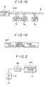
- FIGS. 1A and 1B are diagrams illustrative of the principles of the present invention.
- FIG. 2 is a block diagram of a power supply circuit for an audiovisual system.
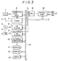
- FIG. 3 is a block diagram of an audiovisual system.
- FIG. 4 is a block diagram of a control network of the audiovisual system.
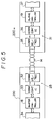
- FIG. 5 is a block diagram of a specific arrangement in which a master unit and a slave unit are connected to each other.
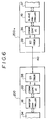
- FIG. 6 is a block diagram of another specific arrangement in which a master unit and a slave unit are connected to each other.
- FIG. 7 is a diagram of a transfer format of communication data.
- FIG. 8 is a diagram of major classification data.
- FIG. 9 is a diagram of subclassification data.
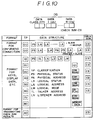
- FIG. 10 is a diagram of basic data formats.
- FIG. 11 is a diagram showing physical addresses.
- FIG. 12 is a diagram showing physical addresses.
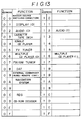
- FIG. 13 is a diagram showing logical addresses.
- FIG. 14A and 14B are diagrams showing physical status data in detail.
- FIG. 15 is a diagram illustrative of an axample in which physical and logical addresases are assigned.
- FIG. 16 is a diagram showing a communication process by way of example.
- FIG. 17 is a diagram of a master unit and an additional slave unit which is newly connected.
- FIGS. 1A and 1B show the principles of the present invention.
- a master unit M and a plurality of slave units S 1 ⁇ S n are connected to a communication bus B.
- the master unit M always transmits master status information MST to the slave units S 1 ⁇ S n , the master status information MST representing a command for a unified operation to be effected by all the slave units S 1 ⁇ S n .
- the slave units S 1 ⁇ S n receive the status information MST, the slave units S 1 ⁇ S n effect the operation indicated by the master status information MST.
- the master unit M when the master unit M issues a command for a unified operation to the slave units S 1 ⁇ S n , the master unit M generates master status information MST representing the contents of the unified operation command.
- the unified operation command may, for example, be mute-mode ON/OFF command for lowering the level of sounds reproduced by the slave units S 1 ⁇ S n .
- the master status information MST is transmitted to all the slave units S 1 ⁇ S n connected to the communication bus B. In response to the master status information MST, the slave units S 1 ⁇ S n operate according to the contents of the master status information MST.
- the master unit M transmits a mute-mode ON command to all the slave units S 1 ⁇ S n
- the master status information MST which includes a status flag indicative of a mute-mode ON status is transmitted to the communication bus B at all times.
- any slave unit which has previously failed to receive the mute mode ON command or a newly connected slave unit can place itself in a mute mode according to the master status information MST. Consequently, the slave units S 1 ⁇ S n operate according to the unified operation command from the master unit M, so that the entire data communication system is able to effect the unified operation.
- the audiovisual system denoted at 103
- the audiovisual system is supplied with electric energy from a battery 101 through an ACC switch 102.
- the ACC switch 102 is assembled together with an engine start keyswitch of the automobile.
- the engine key inserted in the engine start keyswitch is turned to the position of the ACC switch, the accessories on the automobile are energized by the battery 101. Therefore, the audiovisual system 103 is turned on or off each time the engine key is turned in the engine start keyswitch.
- FIG. 3 shows a detailed systematic arrangement of the audiovisual system.
- the audiovisual system has audio reproducing components and visual reproducing components.
- the audio reproducing components include a cassette tape deck 6 for reproducing recorded audio signals from a cassette tape 1, a tuner 7 such as an AM/FM tuner for reproducing radio signals which are received by an antenna 2, a CD player 8 for reproducing recorded signals from a CD 3, and a multiple CD player 9 having an automatic CD changer 5 for reproducing recorded signals from multiple CDs 4.
- the visual reproducing components include a TV tuner contained in the tuner 7, for reproducing TV signals received by the antenna 2, and a display unit 12 for displaying images based on the TV signals and also displaying still images based on signals from the CD player 8 if a CD-ROM is played back by the CD player 8.
- a CD-ROM is employed by a navigation system.
- the audiovisual system has an external commander 10 which is in the form of a keyboard for entering various operaiton commands.
- a display unit 11 is connected to the external commander 10.
- the audiovisual system also has an input unit 13, which may be incorporated in the external commander 10.
- the above components of the audiovisual system have respective controllers for controlling their own operation. These controllers are connected to each other through a communication bus 14, thereby making up a communication bus control network.
- the control network is shown in FIG. 4, and will be described in detail later on.
- Reproduced signals from the audio reproducing components are selectively applied through a selector 15 to a digital amplifier 16. After the reproduced signal has been amplified by the digital amplifier 16, it is applied to loudspeakers 17 from which reproduced sounds are outputted.
- the digital amplifier 16 contains a digital signal processing circuit which is controlled by a controller in the digital amplifier 16, the controller being connected to the communication bus 14.
- FIG. 4 shows the control network in detail.
- the audiovisual system components connected to the communication bus 14 as shown in FIG. 3 will hereinafter be referred to as "units".
- these units are connected to the communication bus 14 parallel to each other. Either one of these units is selected as a "master” unit, indicated by 200, for controlling the control network, while the other units serve as “slave” units, indicated by 200 -1 ⁇ 200 -n .
- the master unit 200 has a master controller 18 connected through a communication interface IC 25 to a communication bus 14.
- the master controller 18 includes controllers for controlling the cassette tape deck 6 and the tuner 7.
- the controller for the cassette tape back 6 also controls the automatic CD changer 5.
- the slave units 200 -1 ⁇ 200 -n have respective slave controllers 19 ⁇ 24 which are also connected to the communication bus 14 through respective communication interface ICs 26 ⁇ 31.
- FIG. 5 shows a specific arrangement in which the master unit 200 and the slave unit 200 -n are connected to each other.
- the master unit 200 and the slave unit 200 -n are connected to each other by the communication bus 14.
- the communication bus 14 comprises a twisted pair of conductors. Communication data DT transferred through the communication bus 14 is transmitted and received by the communication interface ICs 25, 31 of the master unit 200 and the slave unit 200 -n , respectively.
- the communication interface IC 25 is divided into a communication driver/receiver 32 and a communication control IC 33.
- the communication interface IC 31 is divided into a communication driver/receiver 35 and a communication control IC 36.
- the communication control IC 33 is composed of a CMOS transistor, while the communication driver/receiver 32 is composed of a bipolar transistor of high current-driven capability.
- the communication driver/receiver 35 and the communication control IC 36 are of the same structures as the communication driver/receiver 32 and the communication control IC 33.
- the communication interface IC 25 for example, which is divided into the communication control IC 33 and the communication driver/receiver 32, is capable of coping with different transmission mediums for the communication bus 14.
- the communication bus 14 is composed of a twisted pair of conductors for differential transmission. If the communication bus 14 comprises an optical communication cable 40 as shown in FIG. 6, then the communication driver/receiver 32 shown in FIG. 5 may be replaced with an electro-optical transducer 38 with the communication control IC 33 remaining unchanged.
- Another advantage is that since the master unit 200 fails due primarily to disturbance noise entering from the communication bus 14, only the communication driver/receiver 32 will malfunction when an excessive signal is applied thereto form the communication bus 14, and replacing the malfuncitoning communication driver/receiver 32 with a new one will restore the master unit 200. Consequently, the maintenance of the master unit 200 and also the slave unit 200 -n is relatively easy to carry out. The easy maintenance is particularly advantageous with audiovisual systems on automobiles because the master and slave units are exposed to noise induced by the automobile engines.
- bipolar transistors and CMOS transistors are easier and less expensive than the fabrication of Bi-CMOS ICs.
- each of the communication interfaces 26 ⁇ 31 of the other slave units 200 -1 ⁇ 200 -n is also divided into a communication control IC and a communication driver/receiver.
- unified command data When the master unit 200 transmits a unified operation command (hereinafter referred to as "unified command data") to the slave units 200 -1 ⁇ 200 -n , the master unit 200 generates master status data MST representing the contents of the unified command data, and issues the master status data MST onto the communication bus 14 at all times or periodically.
- An operation program for generating and issuing the master status data MST is stored in the master controller 18.
- the master status data MST will be described later on.
- the slave units 200 -1 ⁇ 200 -n are arranged to operate according to the contents of the master status data MST which has been issued onto the communication bus 14.
- An operation program for operating the slave units 200 -1 ⁇ 200 -n according to the master status data MST is stored in each of the slave controllers 19 ⁇ 24.
- FIG. 7 shows a transfer format of the communication data DT.
- the communication data DT comprises, from its leading end, master address data MA indicating the address of the master unit 200, slave address data SA indicating the addresses of the slave units 200 -1 ⁇ 200 -n , message length data N indicating the message length of data D, classification data TP indicating the type of the data D, and the data D itself which represents the contents to be transferred.
- the master and slave address data form address data AD and the classification data Tp and the data D form data group DG to be sent.
- the arrangement of the data D varies depending on the contents of the communication data DT, i.e., the classification data TP.
- the first format is a format for confirming a connection
- the second format is a format for keys and display data
- the third format is a format for transmitting the result of a check sum CS.
- the format for confirming a connection which is used when the communicaiton data DT is transferred from the slave units 200 -1 ⁇ 200 -n to the master unit 200, differs from that which is used when the communicaiton data DT is transferred from the master unit 200 to the slave units 200 -1 ⁇ 200 -n .
- the format for keys and display data as shown in FIG. 10, data ranging from physical status data PS mentioned after to logical mode data LM are all identical, and omitted from illustration.
- Talker address data TL indicates the address of a transmitting side (talker) which transmits the communication data DT.
- Listener address data LN indicates the address of a receiving side (listener) which receives the communication data DT.
- Logical status data LS represents the status of the function corresponding to each logical address LA.
- Logical mode data LM represents the operation status (mode) of the function corresponding to each logical address LA.
- the check sum data CS is data for detecting an added error to improve the reliability of the data D.
- the classification data TP is positioned at the leading end of the communication data DT, and is a data area indicating the type of the data D following the classification data TP.
- the classification data TP is composed of major classification data TP L and subclassification data TP S .
- the major classification data TP L represents the type of the data D. If the entire classification data TP is of 8 bits, then the major classification data TP L is allotted four high-order bits.
- the subclassification data TP S is mainly used to identify the format of the data D, and is allotted four low-order bits.
- the classification data TP composed of the main classification and subclassification data TP L , TP S is added, various command data are not mixed in one packet of communication data DT, and one packet of communication data DT may be short and simplified.
- the communication data DT can thus be systematized, and processed simply by transmitting and receiving units. Shortened packets of communication data are effective to reduce the time in which the communication bus is occupied by the communication data being transmitted, resulting in an increase in the data transfer efficiency Since the major classification and subclassification data are positioned in the leading portion of the communication data DT, the type of the communication data can easily be identified by the receiving unit for easy debugging failure analysis.
- the physical address data PA represents communication addresses for specifying the communication interface ICs 25 ⁇ 31 of the master unit 200 and the slave units 200 -1 ⁇ 200 -n on the communicatlon bus 14, that is the addresses indicating the master unit 200 and the slave units 200 -1 ⁇ 200 -n .
- the physical address data PA for specifying the master unit 200 is fixed at all times. Basically, one unit is allotted one physical address data PA.
- FIG. 15 shows an example in which the units shown in FIG. 4 are allotted physical address data. In FIG. 15, the physical address data PA are established for the master and slave controllers 18 ⁇ 24.
- the physical status data PS represents status information about the master unit 200 and the slave units 200 -1 ⁇ 200 -n , and includes data indicative of the number of function addresses (i.e.,the logical address data LA, described below) that the units have.
- FIGS. 14A and 14B show in detail the formats of the physical status data PS.
- the physical status data PS includes master status data MST issued by the master unit 200 and slave status data SST issued by the slave units 200 -1 ⁇ 200 -n .
- the master status data MST has four higher-order bits representing the number of logical addresses LA thereof, and lower-order bits representing a status expansion or extension bit SE, an operation permission flag ENF, a mask-mode ON/OFF flag MOF, and a mute-mode ON/OFF flag MUF.
- the status expansion bit SE is used when an additional status is present.
- the operation permission flag ENF is set to "1" when the master unit 200 stops issuing an enable ON command and is operable.
- the mask-mode ON/OFF flag MOF represents a masking condition with respect to all the slave unit 200 -1 ⁇ 200 -n and is set to "1" when a mask mode is ON.
- the mask mode is initiated by a mask command which prevents the master unit 200 and the slave units 200 -1 ⁇ 200 -n from detecting ON/OFF statuses of the ACC switch 101.
- the mute-mode ON/OFF flag MUF is a flag indicating, to all the slave units 200 -1 ⁇ 200 -n , that the entire audiovisual system is mute, and is set to "1" when the mute mode is ON.
- the slave status data SST has four higher-order bits representing the number of logical addresses LA, lower-order bits representing a status expansion bit and a mute-function presence/absence flag MBF, and other bits OB.
- the mute-function presence/absence flag MBF is a flag indicating whether the slave units 200 -1 ⁇ 200 -n have a mute function or not.
- the flag MBF is set to "1" when the slave units 200 -1 ⁇ 200 -n have the mute function. Though not all the slave units 200 -1 ⁇ 200 -n have the mute function, almost all slave units in the form of audio sound systems have the mute function, and the display unit does not have the mute function.
- the logical address data LA is data indicative of each of the functions (i.e., the tuner and the cassette tape deck) possessed by the master unit 200 and the slave units 200 -1 ⁇ 200 -n .
- the logical address data LA is assigned to each function.
- the number of logical address data LA is not fixed because there are as many logical address data LA (e.g., LA 1 , LA 2 , ...LA n ) as there are functions possessed by the controller that is determined by the physical address data PA.
- FIG. 15 also shows the logical address data LA assigned to the units shown in FIG. 4.
- the communication ICs 25 ⁇ 31 have communication physical addresses PA.
- Each of the master and slave units 200, 200 -1 , ... 200 -6 has a function physical address PA F and the logical address LA.
- the master controller 18 includes two controllers for controlling the cassette tape deck 6 and the tuner 7, and, therefore, two logical addresses LA are assigned to those two controllers.
- a controller of the slave unit 200 -3 includes a display controller and an external commander controller and, therefore, a logical address is assigned to each controller.
- the logical address is equal to the function physical address.
- FIG. 16 shows a specific communication process or sequence for confirming a connection when the master unit 200 is accessed by a slave unit including TV and FM/AM tuners to confirm the connection of the slave unit to the audiovisual system.
- the slave units send a self report about themselves to the master unit 200, unlike the conventional polling process.
- the master unit does not initially positively access the slave units.
- the slave unit transmits communication data DT 1 for requesting the confirmation of a connection by way of a self report, to the master unit 200 through the communication bus 14.
- the master unit 200 transmits return data RDT 1 back to the slave unit, indicating that the master unit 200 has received the communication data DT 1 . Then, in order to let the newly connected slave unit know the members or components of the audiovisual system, the master unit 200 transmits system connection information DT 2 to the slave unit.
- the slave unit When the system connection information DT 2 is received, the slave unit transmits return data RDT 2 back to the master unit 200 to confirm the reception of the system connection information DT 2 . After elapse of a predetermined period of time, the slave unit transmits communication data DT 3 concerning a request for confirming a connection (self report) again to the master unit. The communication data DT 3 is transmitted again because the connection must be confirmed periodically since the audiovisual system on the automobile is turned on and off depending on the ACC switch.
- the communication data DT includes the physical address data PA and the logical address data LA, and the physical address data PA and the logical address data LA are independent of each other. Therefore, any desired combination of physical and logical address data PA, LA may be employed to transmit communication data to any desired unit.
- the format of the communication data DT and the allotment of addresses to the units are different between the physical address data PA and the logical address data LA.
- a new unit can be connected and can communicate with existing units provided logical address data LA are clearly established.
- the communication data DT transmitted to the slave units 200 -1 ⁇ 200 -n by the master unit 200 contains the physical status data PS.
- the slave units 200 -1 ⁇ 200 -n operate according to the contents of the physical status PS in the communication data DT that is received.
- the master unit 200 issues unified command data to turn on the mute mode, for example, to the slave units 200 -1 ⁇ 200 -n
- the master unit 200 generates the master status data MST as shown in FIG. 14A, and issues the generated master status data MST onto the communication bus 14.
- the slave unit which have already received the unified command data to enter the mute mode.
- the master unit 200 transmits the physical status data PS at all times (i.e., each time the communication data DT is issued)
- the new slave unit can quickly enter the mute mode according to the status of the master unit 200 (i.e., the status which the audiovisual system is to take ). Therefore, the audiovisual system enter the unified mode.
Landscapes
- Engineering & Computer Science (AREA)
- Computer Networks & Wireless Communication (AREA)
- Signal Processing (AREA)
- Small-Scale Networks (AREA)
- Selective Calling Equipment (AREA)
Claims (12)
- Système pour transmettre des données dans un réseau de communications, le système comprenant:- un bus de transmission (B, 14) pour transmettre des informations;- une unité maîtresse (M, 200) connectée audit bus de transmission; et- une pluralité d'unités esclaves S1 à Ns, 200-1 à 200-n) connectées audit bus de transmission,ladite unité maîtresse ayant des moyens générateurs (25) pour produire une commande d'opération unifiée prédéterminée pour lesdites unités esclaves,
caractérisé en ce que:- lesdits moyens générateurs (25) émettent des données de communications, lesdites données de communications incluant des informations d'état qui comprennent une pluralité de drapeaux, chaque drapeau indiquant qu'une desdites commandes d'opération unifiée a été émise, et émettant, périodiquement ou de manière continue, lesdites données de communications sur ledit bus de transmission; et- chacune desdites unités esclaves étant agencée pour fonctionner selon le contenu des informations d'état comprises dans les données de communications émises. - Système selon la revendication 1, dans lequel ladite commande d'opération unifiée représente des données de commande unifiée pour un mode de blocage audio.
- Système selon la revendication 1, le système étant monté dans une automobile, et dans lequel ladite commande d'opération unifiée représente des données de commande unifiée pour un mode de masquage dans lequel lesdites unités maîtresse et esclaves ne détectent pas l'état fermé ou ouvert d'un interrupteur d'accessoires (102) de ladite automobile.
- Système selon la revendication 1, le système étant installé dans une automobile, dans lequel lesdites informations d'état incluent des données représentant le nombre d'adresses logiques correspondant au nombre de fonctions dont ladite unité maîtresse est pourvue, des données pour une autorisation d'opération indiquant si ladite unité maîtresse peut être utilisée, des données pour un mode de masquage, dans lequel lesdites unités maîtresse et esclaves ne détectent pas l'état fermé ou ouvert d'un interrupteur d'accessoires (102) de ladite automobile, et des données pour un mode de blocage audio, dans lequel le système audiovisuel complet a sa sortie audio bloquée, lesdites données étant envoyées à chaque régisseur (19, 24) desdites unités esclaves.
- Système selon la revendication 4, dans lequel lesdites informations d'état incluent un binaire d'extension d'état signifiant des données supplémentaires à transmettre lorsqu'un état supplémentaire est présent dans l'unité maîtresse.
- Système selon la revendication 4, dans lequel ledit régisseur (19, 24) de chaque unité esclave est adapté pour émettre des informations d'état qui comprennent des données représentant le nombre d'adresses logiques corresponddant au nombre de fonctions dont ladite unité esclave est pourvue, et des données représentant la présence ou l'absence d'une fonction de blocage audio indiquant si ladite unité esclave a une fonction de blocage audio ou non.
- Système selon la revendication 6, dans lequel lesdites informations d'état émises par ledit régisseur (19, 24) incluent un binaire d'extension d'état signifiant des données supplémentaires à émettre par ledit régisseur quand un état supplémentaire est présent dans l'unité esclave.
- Système selon l'une quelconque des revendications 1 à 7, dans lequel lesdites informations d'état sont envoyées, combinées avec les données de communications transmises entre lesdites unité maîtresse et unités esclaves auxdites unités esclaves (S1 à Ns, 200-1 à 200-n), lesdites données de communications incluant des données d'adresses physiques correspondant à chacune desdites unités maîtresse et esclaves, et des données d'adresses logiques correspondant à une fonction dont chaque unité est pourvue, lesdites données d'adresses physiques et logiques étant indépendantes les unes des autres.
- Système selon l'une quelconque des revendications 1 à 8, dans lequel ledit bus de transmission comprend une paire torsadée de conducteurs (14).
- Système selon l'une quelconque des revendications 1 à 9, dans lequel chacune desdites unités maîtresse et esclaves comprend un régisseur maître, une interface de communications comprenant un circuit intégré de commande de transmission (33, 36) et un circuit d'attaque et récepteur de communications (32, 35) formés chacun séparément de l'autre.
- Système selon la revendication 10, dans lequel ledit circuit intégré de commande de transmission comprend un transistor CMOS, et ledit circuit d'attaque et récepteur de communications comprend un transistor bipolaire pouvant débiter un fort courant.
- Système selon l'une quelconque des revendications 1 à 8, dans lequel le bus de transmission comprend un câble de transmission optique (40) et chacune desdites unités maîtresse et esclaves comprend un régisseur maître et une interface de communications comprenant un circuit intégré de commande de transmission (33, 36) et un transducteur électro-optique (38, 39) formés chacun séparément de l'autre.
Applications Claiming Priority (2)
| Application Number | Priority Date | Filing Date | Title |
|---|---|---|---|
| JP02288223A JP3100975B2 (ja) | 1990-10-25 | 1990-10-25 | データ通信システム |
| JP288223/90 | 1990-10-25 |
Publications (3)
| Publication Number | Publication Date |
|---|---|
| EP0482958A2 EP0482958A2 (fr) | 1992-04-29 |
| EP0482958A3 EP0482958A3 (en) | 1993-06-02 |
| EP0482958B1 true EP0482958B1 (fr) | 1997-01-15 |
Family
ID=17727422
Family Applications (1)
| Application Number | Title | Priority Date | Filing Date |
|---|---|---|---|
| EP91309910A Expired - Lifetime EP0482958B1 (fr) | 1990-10-25 | 1991-10-25 | Système de communication de données |
Country Status (3)
| Country | Link |
|---|---|
| EP (1) | EP0482958B1 (fr) |
| JP (1) | JP3100975B2 (fr) |
| DE (1) | DE69124188T2 (fr) |
Families Citing this family (4)
| Publication number | Priority date | Publication date | Assignee | Title |
|---|---|---|---|---|
| US6131129A (en) * | 1997-07-30 | 2000-10-10 | Sony Corporation Of Japan | Computer system within an AV/C based media changer subunit providing a standarized command set |
| JP3462793B2 (ja) * | 1999-05-28 | 2003-11-05 | 三洋電機株式会社 | オーディオ・コンポーネント・システム |
| CN100508454C (zh) * | 2004-07-16 | 2009-07-01 | 佛山市顺德区顺达电脑厂有限公司 | 主从元件间的数据传输方法 |
| JP4575324B2 (ja) | 2006-03-29 | 2010-11-04 | 株式会社東芝 | Av装置及びその制御方法 |
Family Cites Families (3)
| Publication number | Priority date | Publication date | Assignee | Title |
|---|---|---|---|---|
| US4715031A (en) * | 1985-09-23 | 1987-12-22 | Ford Motor Company | Vehicular data transfer communication system |
| US4855730A (en) * | 1987-05-08 | 1989-08-08 | Rca Licensing Corporation | Component audio/video system with timed control of plural peripheral devices |
| US5107256A (en) * | 1987-11-02 | 1992-04-21 | Matsushita Electric Industrial Co., Ltd. | Method and apparatus for controlling terminals on communication network |
-
1990
- 1990-10-25 JP JP02288223A patent/JP3100975B2/ja not_active Expired - Fee Related
-
1991
- 1991-10-25 DE DE1991624188 patent/DE69124188T2/de not_active Expired - Fee Related
- 1991-10-25 EP EP91309910A patent/EP0482958B1/fr not_active Expired - Lifetime
Non-Patent Citations (1)
| Title |
|---|
| Electro/81 Conference Record, Vol. 6 (1981), New York US, pages 9/1/1-9/1/10; Don Foulkes: "Serial Network simplifies the design of multiple microcomputor systems." * |
Also Published As
| Publication number | Publication date |
|---|---|
| JPH04160945A (ja) | 1992-06-04 |
| EP0482958A3 (en) | 1993-06-02 |
| DE69124188T2 (de) | 1997-07-03 |
| EP0482958A2 (fr) | 1992-04-29 |
| DE69124188D1 (de) | 1997-02-27 |
| JP3100975B2 (ja) | 2000-10-23 |
Similar Documents
| Publication | Publication Date | Title |
|---|---|---|
| EP0482957B1 (fr) | Procédé de communication de données dans un réseau de communication d'un véhicule automobile | |
| EP0515042B1 (fr) | Système pour la communication de données dans une automobile | |
| US5280281A (en) | Method of and system for data communication in communication network on automobile | |
| JPH04326834A (ja) | 車載用データ通信システム | |
| US5436851A (en) | System for data communication | |
| EP0482958A2 (fr) | Système de communication de données | |
| EP0511010A2 (fr) | Système de communication de données pour automobile | |
| EP0482952B1 (fr) | Méthode de communication de données dans un réseau de communication d'automobile | |
| EP0482951B1 (fr) | Méthode et système pour la communication de données dans un réseau de communication d'une automobile | |
| JP3026359B2 (ja) | 車載用通信ネットワークにおけるデータ通信方法 | |
| JP3065651B2 (ja) | 車載用通信ネットワークにおけるデータ通信方法 | |
| JP3100997B2 (ja) | 車載用データ通信システム | |
| JP2978551B2 (ja) | データ通信方法 | |
| JP3090463B2 (ja) | データ通信システム | |
| JP2966502B2 (ja) | 車載用通信ネットワークにおけるデータ通信方法 | |
| JPH04326896A (ja) | 車載用データ通信システム | |
| JP3065652B2 (ja) | 車載用通信ネットワークにおけるデータ通信方法 | |
| JPH04160943A (ja) | オーディオシステムにおけるデータ通信方法 | |
| JPH04326900A (ja) | 車載用データ通信システム | |
| JPH04326899A (ja) | 車載用データ通信システム | |
| JP3045326B2 (ja) | 車載用データ通信システム | |
| JPH04160934A (ja) | 車載用データ通信システム | |
| JPH04160932A (ja) | 通信インターフェイス装置 | |
| JPH04160937A (ja) | データ通信システム | |
| JPH04160936A (ja) | 車載用通信ネットワークにおけるデータ通信方法 |
Legal Events
| Date | Code | Title | Description |
|---|---|---|---|
| PUAI | Public reference made under article 153(3) epc to a published international application that has entered the european phase |
Free format text: ORIGINAL CODE: 0009012 |
|
| AK | Designated contracting states |
Kind code of ref document: A2 Designated state(s): DE FR GB |
|
| PUAL | Search report despatched |
Free format text: ORIGINAL CODE: 0009013 |
|
| AK | Designated contracting states |
Kind code of ref document: A3 Designated state(s): DE FR GB |
|
| 17P | Request for examination filed |
Effective date: 19931130 |
|
| 17Q | First examination report despatched |
Effective date: 19941216 |
|
| GRAG | Despatch of communication of intention to grant |
Free format text: ORIGINAL CODE: EPIDOS AGRA |
|
| GRAH | Despatch of communication of intention to grant a patent |
Free format text: ORIGINAL CODE: EPIDOS IGRA |
|
| GRAH | Despatch of communication of intention to grant a patent |
Free format text: ORIGINAL CODE: EPIDOS IGRA |
|
| GRAA | (expected) grant |
Free format text: ORIGINAL CODE: 0009210 |
|
| AK | Designated contracting states |
Kind code of ref document: B1 Designated state(s): DE FR GB |
|
| REF | Corresponds to: |
Ref document number: 69124188 Country of ref document: DE Date of ref document: 19970227 |
|
| ET | Fr: translation filed | ||
| PG25 | Lapsed in a contracting state [announced via postgrant information from national office to epo] |
Ref country code: GB Free format text: LAPSE BECAUSE OF NON-PAYMENT OF DUE FEES Effective date: 19971025 |
|
| PLBE | No opposition filed within time limit |
Free format text: ORIGINAL CODE: 0009261 |
|
| STAA | Information on the status of an ep patent application or granted ep patent |
Free format text: STATUS: NO OPPOSITION FILED WITHIN TIME LIMIT |
|
| 26N | No opposition filed | ||
| REG | Reference to a national code |
Ref country code: FR Ref legal event code: D6 |
|
| GBPC | Gb: european patent ceased through non-payment of renewal fee |
Effective date: 19971025 |
|
| PGFP | Annual fee paid to national office [announced via postgrant information from national office to epo] |
Ref country code: DE Payment date: 20081027 Year of fee payment: 18 |
|
| PGFP | Annual fee paid to national office [announced via postgrant information from national office to epo] |
Ref country code: FR Payment date: 20081014 Year of fee payment: 18 |
|
| REG | Reference to a national code |
Ref country code: FR Ref legal event code: ST Effective date: 20100630 |
|
| PG25 | Lapsed in a contracting state [announced via postgrant information from national office to epo] |
Ref country code: FR Free format text: LAPSE BECAUSE OF NON-PAYMENT OF DUE FEES Effective date: 20091102 Ref country code: DE Free format text: LAPSE BECAUSE OF NON-PAYMENT OF DUE FEES Effective date: 20100501 |