EP0483371B1 - Unite de commande d'impression - Google Patents
Unite de commande d'impression Download PDFInfo
- Publication number
- EP0483371B1 EP0483371B1 EP91909091A EP91909091A EP0483371B1 EP 0483371 B1 EP0483371 B1 EP 0483371B1 EP 91909091 A EP91909091 A EP 91909091A EP 91909091 A EP91909091 A EP 91909091A EP 0483371 B1 EP0483371 B1 EP 0483371B1
- Authority
- EP
- European Patent Office
- Prior art keywords
- printing
- time
- moving speed
- correction
- correction value
- Prior art date
- Legal status (The legal status is an assumption and is not a legal conclusion. Google has not performed a legal analysis and makes no representation as to the accuracy of the status listed.)
- Expired - Lifetime
Links
- 230000008602 contraction Effects 0.000 claims abstract description 32
- 230000001133 acceleration Effects 0.000 claims abstract description 23
- 230000001360 synchronised effect Effects 0.000 claims abstract 2
- 238000010586 diagram Methods 0.000 description 5
- 238000010276 construction Methods 0.000 description 2
- 238000007796 conventional method Methods 0.000 description 1
- 230000007423 decrease Effects 0.000 description 1
- 230000003111 delayed effect Effects 0.000 description 1
- 238000001514 detection method Methods 0.000 description 1
Images


Classifications
-
- B—PERFORMING OPERATIONS; TRANSPORTING
- B41—PRINTING; LINING MACHINES; TYPEWRITERS; STAMPS
- B41J—TYPEWRITERS; SELECTIVE PRINTING MECHANISMS, i.e. MECHANISMS PRINTING OTHERWISE THAN FROM A FORME; CORRECTION OF TYPOGRAPHICAL ERRORS
- B41J19/00—Character- or line-spacing mechanisms
- B41J19/18—Character-spacing or back-spacing mechanisms; Carriage return or release devices therefor
- B41J19/20—Positive-feed character-spacing mechanisms
- B41J19/202—Drive control means for carriage movement
Definitions
- the present invention relates to a printing control system suitable for a printer such as a serial-dot printer by which printing operation is effected by shifting a printing head.
- Fig. 1 shows a carriage driving mechanism for an ordinary serial-dot printer, in which printing to a printing medium 13 (e.g. paper) is made by converting the rotational motion of a carriage drive motor 4 into a linear motion via a pulling member (e.g. belt) 10 and pulleys 11 so that a carriage 12 for mounting a printing head 7 can travel at a predetermined speed. Further, the positional control of the carriage 12, that is, the printing position control is effected on the basis of the output pulse of an encoder 5 mounted on the carriage drive motor 4.
- a printing medium 13 e.g. paper
- a pulling member e.g. belt
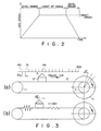
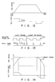
- Fig. 2 shows a driving pattern of the carriage drive motor 4 required when printing data for one line are printed.
- the printing operation is effected when the carriage 12 travels at a target constant speed.
- the travel distance of the carriage 12 from when a printing command is given to when the ends of wires reach the printing medium 13 to form dots differs according to the travel speed of the carriage 12, thus resulting in a problem in that dot intervals are not equalized when the printing operation is made under the condition that the travel speed of the carriage 12 is not kept at a constant value.
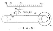
- FIG. 3 is a simplified model view of the carriage drive mechanism, in which (a) shows the status where the carriage is driven in an ideal fashion without influence of elastic component and (b) shows the status where the carriage is accelerated in the arrow direction under influence of elastic component.
- a torque generated by the carriage drive motor 4 is transmitted to the carriage 12 under the condition that the belt is being expanded by ⁇ E on the travel direction side (contracted on the opposite side).
- a torque generated by the carriage motor 4 is transmitted to the carriage 12 under the condition that the belt is being contracted on the travel direction side (expanded on the opposite side).
- the expansion and contraction of the belt 10 are discussed only on the travel direction side.
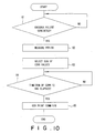
- the reference numeral 502 denotes a graduation obtained by converting the encoder pulse generated by the encoder 5 for each constant revolutional angle ⁇ r of the carriage drive motor 4 into the travel distance of the carriage 12, in which the rotational angle ⁇ r corresponds to the travel stroke ⁇ x of the carriage 12.
- the printing command signals are given on the basis of the rotational angle of the carriage drive motor 4. Therefore, the printing command signals are generated on the assumption that the carriage 12 travels by ⁇ x whenever the carriage drive motor 4 rotates through the ⁇ r. In the conventional method, the correction has been started at this time according to the flight time and the travel speed of the carriage 12.
- the carriage 12 travels by a distance n ⁇ ⁇ x as illustrated, when the carriage motor 4 rotates by n ⁇ ⁇ r and an encoder pulse signal corresponding to the position Pn is generated.
- the carriage drive motor 4 rotates by n ⁇ ⁇ r during acceleration and an encoder pulse corresponding to the position Pn is generated, since the belt 10 is elongated by ⁇ E, there exists a problem in that the printed pots are offset by ⁇ E from the correct position Pn.
- the dot intervals can be kept constant.
- the expansion and contraction rate varies in such a way that the belt is expanded during acceleration, kept zero at a constant speed, and contracted during deceleration, the dot intervals cannot be kept constant.
- the problem of the present invention is to provide a printing control system which can equalize dot intervals even if printing operation is effected during acceleration or deceleration of the carriage.
- Fig. 4 is a block diagram showing a printing control system for a wire dot printer according to the present invention.
- the reference numeral 4 denotes a carriage drive motor.
- the rotational angle of this carriage drive motor 4 is detected by an encoder 5.
- the encoder 5 generates an encoder pulse signal 501 and inputs the generated signal to a control section A for each predetermined rotational angle of the carriage drive motor 4.
- the control section A generates a printing command signal 301 on the basis of the pulse signal 501 from the encoder 5 to actuate a printing head 7 via a wire driving circuit 6 for printing operation.
- Fig. 5 shows a practical example of the control section A, which comprises a CPU 8 and a ROM 9.
- the CPU 8 executes processing (described later) in accordance with control programs written in the ROM 9.
- Fig. 4 is a block diagram showing the processing functions of the control section A.
- a speed detecting section 1 of the control section A measures a period T of the encoder pulse signal 501 from the encoder 5.
- This period T is a time duration required when the carriage drive motor 4 rotates through a predetermined unit angle. Therefore, the period T corresponds to the rotational speed of the drive motor 4 and further the travel speed V of the carriage.
- a correction value table indicative of the relationship between the period T (i.e. rotational speed) of the encoder pulse signal 501 and the correction value of the printing timing as shown in Table 1 is stored.
- a correction value deciding section 2 shown in Fig. 4 selects a correction value corresponding to the period T measured by the speed detecting section 1 on the basis of the correction value table.
- the printing command generating section 3 starts to measure time from when receiving the encoder pulse signal 501 from the encoder 5, and generates the printing command signal 301 when a time corresponding to a correction value given by the correction value deciding section 2 has elapsed.
- a motor control section 14 controls the required printing operation of the carriage drive motor 4, which accelerates the carriage drive motor 4 to a target speed, keeps the target speed thereafter, and decelerates the motor 4 so as to be stopped at a predetermined position.
- a control mode discriminating section 15 discriminates whether the control mode of the carriage drive motor 4 is acceleration, constant speed or deceleration, and transmits a signal to the correction value deciding section 2.
- the correction value deciding section 2 selects a correction value corresponding to the period T measured by the speed detecting section 1 and the control mode discriminated by the control mode discriminating section 15, on the basis of the correction value table.
- the relationship between the correction value for correcting the expansion and contraction of the belt 10 and the rotational speed is as follows:
- V the travel speed of the carriage 12 during acceleration
- ⁇ E the time Te required to shift the carriage 12 by ⁇ E
- Te ⁇ E/V
- This value is a correction value corresponding to the speed V.
- a time point delayed by the correction value Te from the detection signal of the up-edge of the encoder pulse signal 501 is a time point at which the carriage 12 reaches a correct printing position.
- a time point a correction value Te before the time point when the up-edge of the encoder pulse signal 501 is detected is a time point at which the carriage 12 reaches a correct printing position.
- the relationship between the correction value for correcting error due to flight time and the rotational speed is as follows:
- the position of the printing head 7 obtained when the carriage travels at the maximum speed V max is determined as a reference value, and the correction is made in such a way that the positions of the printing head 7 at the travel speeds other than the maximum speed are arranged at regular intervals beginning from the reference position.
- the encoder pulse signals 501 are generated at regular distance intervals but time intervals becoming shorter and shorter.
- the printing dot position D1 is offset by S max from the up-edge thereof.
- the printing dot position D2 is offset by S V from the up-edge position. The correction is made in such a way that the offset S V at the speed V becomes equal to the offset S max at the maximum speed V max ; that is, the printing dot position at the speed V is corrected to the position D3 to equalize the respective printing dot intervals.
- Fig. 7 shows the encoder pulse signal 501 and the printing command signal 301 along the time axis.
- correction values Te and Tf corresponding to the period T are selected from the correction value table (corresponding to Table 1) in the ROM 9. If the carriage is being accelerated and the period T is tn as shown in Fig. 7, teACCn is selected as the correction value Te and tfn is selected as Tf (in step 63).
- the suffixes of the reference numerals of the pulse train represent the order of the pulse generation.
- the suffixes of the symbols of the period T simply represent the correspondence to the correction values, without determining the order of the changes in carriage speed such as acceleration or deceleration.
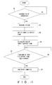
- Fig. 10 is a flowchart showing the operation of the second embodiment of the present invention.
- Table 2 is a correction value table used for this second embodiment, in which numerical values obtained by previously adding the correction values for correcting error caused by the expansion and contraction of the belt 10 and that for correcting error caused by the flight time are stored.
- the period T between the preceding encoder pulse signal EPn-1 and the current encoder pulse signal EPn is measured (in step 82), and a correction value Tdly corresponding to the period T is selected from the Table 2 in the ROM 9. If the period T is tn during acceleration as shown in Fig. 7, tdACCn is selected as the correction value Tdly (in step 83).
- Tdly TORG + Tos
- Tdly tdACCn + ton
- the correction value is always kept at a positive value by introducing the offset value Tos, the correction can be made even if the belt contraction rate during deceleration is large.
- the correction is executed on the assumption that one printing command signal is generated for each encoder pulse signal.
- the correction is executed for the divided or multiplied output signal.
- the printing command signal can be corrected in such a way that both the influences of flight time and belt expansion and contraction can be eliminated, the printing dot intervals can be kept constant at all the times, thus realizing a high speed printing under excellent printing quality such that the printing operation can be effected even when the carriage is being accelerated or decelerated.
- Fig. 12 shows the relationship between the speed pattern of the carriage 12 and the belt expansion and contraction when printing data for one line are printed.
- a trapezoidal pattern as shown in Fig. 12 has conventionally been adopted.
- the belt expansion and contraction conditions are as follows:
- the motor speed is controlled so as to be smoothly changed from a predetermined speed V1 to a target speed; that is, the motor speed is controlled in such a way that the acceleration or the belt expansion rate decreases gradually (e.g. in proportion to the difference between the current speed and the target speed).
- the motor speed it is possible to prevent the time intervals of the printing command signal 301 from being reduced extremely.
- the motor speed is controlled in such a way that the deceleration or the belt contraction rate increases gradually (e.g. in proportion to the difference between the current speed and the target speed).
Landscapes
- Character Spaces And Line Spaces In Printers (AREA)
Abstract
Claims (6)
- Système de commande d'impression dans lequel une tête d'impression (7) effectue un mouvement sous l'action d'un élément de traction (10) couplé à une source d'énergie (4), et un signal d'instruction d'impression, produit en réponse à un signal synchronisé avec le mouvement de la source d'énergie (4), est appliqué à la tête d'impression (7), le système comprenant :
un moyen (1, 5) servant à détecter la vitesse de mouvement de la tête d'impression (7),
un moyen discriminateur (15) servant à décider si la tête d'impression (7) est en train d'accélérer, est en trait de décélérer ou est entraînée à une vitesse constante, et
un moyen (2) servant à corriger le positionnement temporel suivant lequel le signal d'instruction d'impression est produit, en liaison avec le signal de sortie dudit moyen discriminateur (15), c'est-à-dire en liaison avec à la fois le taux de dilatation et de contraction de l'élément de traction (10) et le temps de frappe pour la vitesse de mouvement détectée. - Système de commande d'impression selon la revendication 1, où ledit moyen de correction comprend :
un moyen servant à produire une valeur de correction temporelle comportant la somme d'un premier temps de correction destiné à corriger le positionnement temporel de la production du signal d'instruction d'impression par rapport au taux de dilatation et de contraction de l'élément de traction et d'un deuxième temps de correction destiné à corriger le positionnement temporel de la production du signal d'instruction d'impression par rapport au temps de frappe, en fonction d'une relation prédéterminée entre le premier temps de correction et la vitesse de mouvement de la tête d'impression et d'une autre relation prédéterminée entre le deuxième temps de correction et la vitesse de mouvement de la tête d'impression ; et
un moyen servant à ajuster des intervalles de temps, qui vont du moment où le signal de synchronisation est reçu au moment où le signal d'instruction d'impression est produit, sur la base de la valeur de correction temporelle produite. - Système de commande d'impression selon la revendication 1, où ledit moyen de correction comprend :
un moyen servant à produire une valeur de correction temporelle comportant le temps de correction qui correspond à la vitesse de mouvement détectée en fonction d'une relation prédéterminée entre le temps de correction servant à corriger le positionnement temporel de la production du signal d'instruction d'impression par rapport à la fois au taux de dilatation et de contraction de l'élément de traction et au temps de frappe, et la vitesse de mouvement de la tête d'impression ; et
un moyen servant à ajuster les intervalles de temps qui vont du moment où le signal de synchronisation est reçu au moment où le signal d'instruction d'impression est produit, sur la base de la valeur de correction temporelle produite. - Système de commande d'impression selon la revendication 2 ou 3, où ledit moyen de production de valeur de correction produit des valeurs différentes comme valeur de correction selon qu'une accélération ou une décélération a été déterminée par ledit moyen discriminateur, même si la vitesse de mouvement détectée est la même.
- Système de commande d'impression selon la revendication 4, où ledit moyen de production de valeur de correction décide un temps de décalage correspondant à la vitesse de mouvement détectée en fonction d'une relation inversement proportionnelle prédéterminée entre le temps de correction et la vitesse de mouvement détectée ; et le temps de décalage ainsi décidé est également incorporé dans la valeur de correction temporelle produite de façon que la valeur de correction temporelle produite devienne toujours une valeur positive, indépendamment du fait que la tête d'impression est en train d'accélérer ou de décélérer.
- Système de commande d'impression selon la revendication 1, qui comprend en outre un moyen servant à commander la source d'énergie de façon que l'accélération de la tête d'impression varie de façon régulière.
Applications Claiming Priority (3)
| Application Number | Priority Date | Filing Date | Title |
|---|---|---|---|
| JP12477490 | 1990-05-15 | ||
| JP124774/90 | 1990-05-15 | ||
| PCT/JP1991/000642 WO1991017892A1 (fr) | 1990-05-15 | 1991-05-15 | Unite de commande d'impression |
Publications (3)
| Publication Number | Publication Date |
|---|---|
| EP0483371A1 EP0483371A1 (fr) | 1992-05-06 |
| EP0483371A4 EP0483371A4 (en) | 1993-02-24 |
| EP0483371B1 true EP0483371B1 (fr) | 1995-11-29 |
Family
ID=14893783
Family Applications (1)
| Application Number | Title | Priority Date | Filing Date |
|---|---|---|---|
| EP91909091A Expired - Lifetime EP0483371B1 (fr) | 1990-05-15 | 1991-05-15 | Unite de commande d'impression |
Country Status (6)
| Country | Link |
|---|---|
| US (1) | US5288157A (fr) |
| EP (1) | EP0483371B1 (fr) |
| JP (1) | JP3248169B2 (fr) |
| DE (1) | DE69114993T2 (fr) |
| HK (1) | HK5497A (fr) |
| WO (1) | WO1991017892A1 (fr) |
Families Citing this family (12)
| Publication number | Priority date | Publication date | Assignee | Title |
|---|---|---|---|---|
| JP3495747B2 (ja) * | 1991-07-22 | 2004-02-09 | セイコーエプソン株式会社 | プリンタの印字制御方法及び装置 |
| AU749771B2 (en) * | 1998-03-04 | 2002-07-04 | Ferag Ag | Device for exchanging roll supports on winding stations |
| JP3645708B2 (ja) * | 1998-04-30 | 2005-05-11 | 武藤工業株式会社 | 記録装置 |
| US6601513B1 (en) * | 1999-05-25 | 2003-08-05 | Seiko Precision, Inc. | Motor control method and apparatus, time recorder having same and impact type printing apparatus |
| JP2001232859A (ja) | 2000-02-21 | 2001-08-28 | Seiko Epson Corp | 印刷ヘッドの機械的な振動を考慮した双方向印刷 |
| US6609781B2 (en) | 2000-12-13 | 2003-08-26 | Lexmark International, Inc. | Printer system with encoder filtering arrangement and method for high frequency error reduction |
| EP1287992B1 (fr) | 2001-08-27 | 2009-01-07 | Canon Kabushiki Kaisha | Appareil et méthode d'impression par jet d'encre |
| JP3673745B2 (ja) * | 2001-10-01 | 2005-07-20 | キヤノン株式会社 | 制御装置及びその方法、記録装置及びその制御方法 |
| US7284810B2 (en) | 2002-03-14 | 2007-10-23 | Seiko Epson Corporation | Printer, printing method, program, storage medium and computer system |
| US7753465B2 (en) * | 2006-10-13 | 2010-07-13 | Lexmark International, Inc. | Method for generating a reference signal for use in an imaging apparatus |
| US8197022B2 (en) * | 2009-09-29 | 2012-06-12 | Eastman Kodak Company | Automated time of flight speed compensation |
| JP5845693B2 (ja) * | 2011-07-29 | 2016-01-20 | ブラザー工業株式会社 | 搬送装置及び画像形成装置 |
Family Cites Families (16)
| Publication number | Priority date | Publication date | Assignee | Title |
|---|---|---|---|---|
| US4533268A (en) * | 1982-10-27 | 1985-08-06 | Sanders Jr Roy C | Position indicator for high speed printers |
| US4522517A (en) * | 1983-11-10 | 1985-06-11 | Wade Kenneth B | Encoder system for dot matrix line printer |
| JPS6233662A (ja) * | 1985-08-08 | 1987-02-13 | Alps Electric Co Ltd | プリンタのモ−タ制御方式 |
| JPH0611573B2 (ja) * | 1985-09-18 | 1994-02-16 | キヤノン株式会社 | 記録装置 |
| US4844635A (en) * | 1985-12-11 | 1989-07-04 | International Business Machines Corp. | Wire fire control mechanism for a wire matrix printer |
| JP2563788B2 (ja) * | 1986-03-07 | 1996-12-18 | セイコーエプソン株式会社 | プリンタのキヤリツジ制御方法 |
| JPH0798409B2 (ja) * | 1986-08-29 | 1995-10-25 | 沖電気工業株式会社 | プリンタ |
| JPS6423428A (en) * | 1987-07-20 | 1989-01-26 | Mitsubishi Electric Corp | Recording medium driver and focus tracking device in recording medium driver |
| JPS6490761A (en) * | 1987-10-01 | 1989-04-07 | Citizen Watch Co Ltd | Printer control system |
| JPH01103478A (ja) * | 1987-10-16 | 1989-04-20 | Brother Ind Ltd | 印字装置 |
| JPH01234280A (ja) * | 1988-03-14 | 1989-09-19 | Nec Corp | 印字ヘッドキャリアの移動制御方法およびその装置 |
| JPH0747347B2 (ja) * | 1988-05-09 | 1995-05-24 | シャープ株式会社 | 往復印字方式 |
| JP2536590B2 (ja) * | 1988-05-20 | 1996-09-18 | 沖電気工業株式会社 | プリンタの印刷方法 |
| JPH0270470A (ja) * | 1988-09-06 | 1990-03-09 | Nec Corp | 印字装置 |
| JPH02261678A (ja) * | 1989-03-31 | 1990-10-24 | Brother Ind Ltd | 往復印字の印字位置ずれ補正機能を有するプリンタ |
| US5116150A (en) * | 1991-01-09 | 1992-05-26 | Apple Computer, Inc. | Apparatus and method for mapping and aligning digital images onto printed media |
-
1991
- 1991-05-15 JP JP50878291A patent/JP3248169B2/ja not_active Expired - Fee Related
- 1991-05-15 DE DE69114993T patent/DE69114993T2/de not_active Expired - Fee Related
- 1991-05-15 EP EP91909091A patent/EP0483371B1/fr not_active Expired - Lifetime
- 1991-05-15 US US07/778,908 patent/US5288157A/en not_active Expired - Lifetime
- 1991-05-15 WO PCT/JP1991/000642 patent/WO1991017892A1/fr not_active Ceased
-
1997
- 1997-01-09 HK HK5497A patent/HK5497A/en not_active IP Right Cessation
Also Published As
| Publication number | Publication date |
|---|---|
| EP0483371A4 (en) | 1993-02-24 |
| HK5497A (en) | 1997-01-17 |
| US5288157A (en) | 1994-02-22 |
| DE69114993T2 (de) | 1996-06-20 |
| DE69114993D1 (de) | 1996-01-11 |
| JP3248169B2 (ja) | 2002-01-21 |
| WO1991017892A1 (fr) | 1991-11-28 |
| EP0483371A1 (fr) | 1992-05-06 |
Similar Documents
| Publication | Publication Date | Title |
|---|---|---|
| EP0483371B1 (fr) | Unite de commande d'impression | |
| EP0300823B1 (fr) | Système de positionnement incrémental | |
| EP1287992B1 (fr) | Appareil et méthode d'impression par jet d'encre | |
| EP0077455A1 (fr) | Système de commande de tête d'impression avec contrôle de l'accélération et de la décélération | |
| JPWO1991017892A1 (ja) | 印字制御装置 | |
| US4493570A (en) | Control system for impact printer | |
| EP0585581B1 (fr) | Unité de commande d'un moteur d'avancement du chariot pour une imprimante | |
| US5439301A (en) | Printer controller and method thereof for a printhead assembly | |
| HK1003601B (en) | Carriage motor controller for printer | |
| JPS63112182A (ja) | プリンタ装置 | |
| EP0431731B1 (fr) | Compensation de friction pour commande de vitesse d'une masse | |
| JPH04310766A (ja) | プリンタ | |
| US8297862B2 (en) | Image forming apparatus and method of controlling the same | |
| JP3458718B2 (ja) | シリアルプリンタ及びシリアルプリンタの動作方法 | |
| JPH0448630B2 (fr) | ||
| JPS63162258A (ja) | プリント制御方式 | |
| JP2008040779A (ja) | 位置決め制御装置及び位置決め制御方法 | |
| JPH01135674A (ja) | プリンタの印字制御方式 | |
| EP0061718B1 (fr) | Une machine adaptable à imprimer en série à grande vitesse | |
| JPH0580856A (ja) | モータ制御装置 | |
| JP2002219835A (ja) | 印字制御方法及びその装置 | |
| JP2742243B2 (ja) | 印字補正方法 | |
| JP2021115835A (ja) | 電子機器及びその制御方法 | |
| JP3096195B2 (ja) | 搬送部材駆動方法 | |
| JPH08238803A (ja) | ドットラインプリンタ及びそのシャトル制御方法 |
Legal Events
| Date | Code | Title | Description |
|---|---|---|---|
| PUAI | Public reference made under article 153(3) epc to a published international application that has entered the european phase |
Free format text: ORIGINAL CODE: 0009012 |
|
| 17P | Request for examination filed |
Effective date: 19920114 |
|
| AK | Designated contracting states |
Kind code of ref document: A1 Designated state(s): DE FR GB |
|
| A4 | Supplementary search report drawn up and despatched |
Effective date: 19930104 |
|
| AK | Designated contracting states |
Kind code of ref document: A4 Designated state(s): DE FR GB |
|
| RIN1 | Information on inventor provided before grant (corrected) |
Inventor name: TANAKA, HIROTOMO, C/O SEIKO EPSON CORPORATION |
|
| 17Q | First examination report despatched |
Effective date: 19940722 |
|
| GRAA | (expected) grant |
Free format text: ORIGINAL CODE: 0009210 |
|
| AK | Designated contracting states |
Kind code of ref document: B1 Designated state(s): DE FR GB |
|
| REF | Corresponds to: |
Ref document number: 69114993 Country of ref document: DE Date of ref document: 19960111 |
|
| ET | Fr: translation filed | ||
| PLBE | No opposition filed within time limit |
Free format text: ORIGINAL CODE: 0009261 |
|
| STAA | Information on the status of an ep patent application or granted ep patent |
Free format text: STATUS: NO OPPOSITION FILED WITHIN TIME LIMIT |
|
| 26N | No opposition filed | ||
| REG | Reference to a national code |
Ref country code: GB Ref legal event code: IF02 |
|
| PGFP | Annual fee paid to national office [announced via postgrant information from national office to epo] |
Ref country code: GB Payment date: 20060510 Year of fee payment: 16 |
|
| PGFP | Annual fee paid to national office [announced via postgrant information from national office to epo] |
Ref country code: DE Payment date: 20060511 Year of fee payment: 16 |
|
| PGFP | Annual fee paid to national office [announced via postgrant information from national office to epo] |
Ref country code: FR Payment date: 20060515 Year of fee payment: 16 |
|
| GBPC | Gb: european patent ceased through non-payment of renewal fee |
Effective date: 20070515 |
|
| REG | Reference to a national code |
Ref country code: FR Ref legal event code: ST Effective date: 20080131 |
|
| PG25 | Lapsed in a contracting state [announced via postgrant information from national office to epo] |
Ref country code: DE Free format text: LAPSE BECAUSE OF NON-PAYMENT OF DUE FEES Effective date: 20071201 |
|
| PG25 | Lapsed in a contracting state [announced via postgrant information from national office to epo] |
Ref country code: GB Free format text: LAPSE BECAUSE OF NON-PAYMENT OF DUE FEES Effective date: 20070515 |
|
| PG25 | Lapsed in a contracting state [announced via postgrant information from national office to epo] |
Ref country code: FR Free format text: LAPSE BECAUSE OF NON-PAYMENT OF DUE FEES Effective date: 20070531 |