EP0483970A1 - Dynamically linking code segments in a multiprocessor system - Google Patents
Dynamically linking code segments in a multiprocessor system Download PDFInfo
- Publication number
- EP0483970A1 EP0483970A1 EP91308794A EP91308794A EP0483970A1 EP 0483970 A1 EP0483970 A1 EP 0483970A1 EP 91308794 A EP91308794 A EP 91308794A EP 91308794 A EP91308794 A EP 91308794A EP 0483970 A1 EP0483970 A1 EP 0483970A1
- Authority
- EP
- European Patent Office
- Prior art keywords
- code
- buffer
- dsp
- pointer
- processor
- Prior art date
- Legal status (The legal status is an assumption and is not a legal conclusion. Google has not performed a legal analysis and makes no representation as to the accuracy of the status listed.)
- Ceased
Links
Images



Classifications
-
- G—PHYSICS
- G06—COMPUTING OR CALCULATING; COUNTING
- G06F—ELECTRIC DIGITAL DATA PROCESSING
- G06F5/00—Methods or arrangements for data conversion without changing the order or content of the data handled
- G06F5/06—Methods or arrangements for data conversion without changing the order or content of the data handled for changing the speed of data flow, i.e. speed regularising or timing, e.g. delay lines, FIFO buffers; over- or underrun control therefor
- G06F5/16—Multiplexed systems, i.e. using two or more similar devices which are alternately accessed for enqueue and dequeue operations, e.g. ping-pong buffers
-
- G—PHYSICS
- G06—COMPUTING OR CALCULATING; COUNTING
- G06F—ELECTRIC DIGITAL DATA PROCESSING
- G06F9/00—Arrangements for program control, e.g. control units
- G06F9/06—Arrangements for program control, e.g. control units using stored programs, i.e. using an internal store of processing equipment to receive or retain programs
- G06F9/30—Arrangements for executing machine instructions, e.g. instruction decode
- G06F9/38—Concurrent instruction execution, e.g. pipeline or look ahead
- G06F9/3877—Concurrent instruction execution, e.g. pipeline or look ahead using a secondary processor, e.g. coprocessor
- G06F9/3879—Concurrent instruction execution, e.g. pipeline or look ahead using a secondary processor, e.g. coprocessor for non-native instruction execution, e.g. executing a command; for Java instruction set
-
- G—PHYSICS
- G06—COMPUTING OR CALCULATING; COUNTING
- G06F—ELECTRIC DIGITAL DATA PROCESSING
- G06F9/00—Arrangements for program control, e.g. control units
- G06F9/06—Arrangements for program control, e.g. control units using stored programs, i.e. using an internal store of processing equipment to receive or retain programs
- G06F9/44—Arrangements for executing specific programs
- G06F9/445—Program loading or initiating
- G06F9/44521—Dynamic linking or loading; Link editing at or after load time, e.g. Java class loading
-
- G—PHYSICS
- G10—MUSICAL INSTRUMENTS; ACOUSTICS
- G10H—ELECTROPHONIC MUSICAL INSTRUMENTS; INSTRUMENTS IN WHICH THE TONES ARE GENERATED BY ELECTROMECHANICAL MEANS OR ELECTRONIC GENERATORS, OR IN WHICH THE TONES ARE SYNTHESISED FROM A DATA STORE
- G10H7/00—Instruments in which the tones are synthesised from a data store, e.g. computer organs
- G10H7/002—Instruments in which the tones are synthesised from a data store, e.g. computer organs using a common processing for different operations or calculations, and a set of microinstructions, e.g. programs, to control the sequence thereof
- G10H7/004—Instruments in which the tones are synthesised from a data store, e.g. computer organs using a common processing for different operations or calculations, and a set of microinstructions, e.g. programs, to control the sequence thereof with one or more auxiliary processor in addition to the main processing unit
Definitions
- This invention relates to dynamically linking code segments in multiprocessor systems such as those employing a digital signal processor (DSP) operating under the control of a host computer to generate complex audio signals.
- DSP digital signal processor
- modules might include analogous software implementations of hardware modules such as oscillators, filters, or voltage controlled amplifiers. These modules were found in music synthesizers of the 1970s wherein they were interconnected as desired and as previously described with patch chords or other means.
- the DSP is disabled during these periods when the host is writing additional DSP program modules to the shared memory so as to prevent the DSP from attempting to execute such instructions which have only partially been written out by the host processor to the shared memory.
- a "ping-pong" form of double buffering has long been known in the data processing arts wherein one buffer contains code being executed while a second buffer is being filled. The situation is then reversed wherein the code in the just-filled buffer executes while additional code is being loaded into the first buffer.
- this conventional practice while useful in preventing the host from updating the buffer being executed by the DSP in some instances, is not entirely satisfactory. For example, if the host attempted to update buffers twice in rapid succession such a double buffering technique would not prevent the undesired updating by the host of the buffer being executed by the DSP.
- a computer system comprising first and second processors arranged to access common shared memory, said second processor being adapted to control the transfer of code modules to said shared memory for execution by said first processor, comprising means for causing said first process to execute a first code module in said shared memory during linking of a second code module to said first code module by a said second processor and pointer control means responsive to the location of code currently under execution by said first processor to cause said second processor to transfer said second code module to a location in said shared memory not currently accessed by said first processor.
- a preferred embodiment of the invention includes a host processor and an audio capture and playback adapter having a DSP co-processor.
- the adapter includes shared memory accessible from both the DSP and the host.
- a DSP program is periodically written to the shared memory by the host and executed by the DSP.
- a non ping-pong dual buffer technique is disclosed wherein alternately one buffer is updated or linked by the host.
- two pointer variables are used, each indicating respectively which buffer is currently being executed by the DSP and which has been updated by the host. Initially, both pointer A and pointer B point to buffer A containing the initial DSP code. Each time the DSP requires execution of the configurable problem, it reads pointer B, copies it to pointer A, and then branches to the buffer pointer A points to.
- the host When the host begins to relink to a buffer, it first sets pointer B equal to pointer A, relinks into the opposite buffer as pointer A, and then sets pointer B to this opposite buffer. The host is thereby prevented from updating a buffer currently being executed by the DSP.
- a computerised audio capture and playback system 10 is depicted in simplified form.
- the system includes a computer 12 including a host CPU 22, and an I/O Bus 20. Interconnected to the Bus 20 are numerous peripheral devices well known in the art such as a keyboard 12, display 14, microphone 16, and speaker 18.
- the system 10 with the exception of an audio capture and playback adapter 24 to be hereinafter described may take the form of any conventional personal computer such as the PS/2 (PS/2 is a trademark of the IBM Corp.) computer marketed by the IBM Corporation.
- PS/2 PS/2 is a trademark of the IBM Corp.
- this audio capture and playback adapter (ACPA) 24 in a preferred embodiment it will take the form of an adapter card which may be plugged into an expansion slot which forms a portion of the computer 12.
- This ACPA card will preferably contain a digital signal processor 26 such as the TMS 320 C25 signal processor available from the Texas Instruments Corporation. Additionally the ACPA 24 will include shared memory 28 accessible both by the DSP 26 and the host CPU 22 through the I/O
- ACPA card 24 One purpose of the ACPA card 24 is to receive analog audio data from an audio source such as microphone 16 through the bus 20, and to "capture” or digitise this audio data, store it, and then later retrieve it whereupon it is converted back to analog form and sent out on the I/O bus 20 to an appropriate sound transducer such as a speaker 18.
- the keyboard 12 and 14 will serve conventional purposes well known in the art of facilitating human interface to the computer 12 and are thus not discussed herein. For purposes of simplicity, other necessary components of the computer 12 are omitted for clarity which are well known in the art, such as disk memory and the like.
- an additional important function of the adapter card 24 is to execute code which may generate synthesized sounds.
- executable code is stored in the shared memory 28 which is accessed and executed by the DSP 26, the output of which is passed through the I/O bus 20 to the speaker 18 if desired, recorded, or the like.
- An important notion with respect to the system of Fig. 4 which will be hereinafter described in greater detail relates to the fact that the system 10 of Fig. 1 in which the invention is implemented is a tightly coupled co-processing system wherein shared memory is included accessed by multiple processors such as that of the host CPU 22 and the DSP 26.
- one of the processors is a digital signal processor well known in the art, it will be readily appreciated that the invention is not intended to be so limited and admits to other implementations not involving DSPs but some other form of multiple processors accessing this shared memory 28 to form a tightly coupled co-processing system.
- this shared memory 28 will contain memory locations which may be read by the host CPU 22 as well as the DSP 26 and written into by the CPU 22.
- This shared memory 28 will include code segments or modules which will be executed by the DSP 26 to generate the desired sounds.
- the host CPU 22 it is necessary for the host CPU 22 to load in from time to time additional such code segments for sequential execution by the DSP.
- contention or conflicts may occur with respect to this shared memory 28.
- This relates to the fact that shared memory is accessed in a co-processing environment by multiple processors such as the DSP 26 and CPU 22.
- Fig. 2 a functional block diagram is shown of typical code segments which must be implemented and executed by the DSP 26 to generate audio sounds. It will be noted in passing that although an audio application is discussed, that the invention is not to be so limited but has application to a variety of code modules. It will further be appreciated that the particular function being performed by this code segment 80 of Fig. 2 executed by the DSP 26 could be essentially any function although in the particular embodiment being discussed these functions happen to relate to generation of audio sounds.
- code segment 80 which contains sub blocks such as oscillator 82, filter 84, voltage controlled amplifier (VCA) 86 and various operators 90-94 which may be interconnected in multiple ways to generate many different sounds as desired.
- code segments are analogous to the separate hardware modules found on larger music synthesizers of the 1970s. In the latter case, it was conventional either to use patch chords or a limited set of switchable hardwire interconnections to allow selection and configuration of the modules as desired.
- Additional functions below line 96 such as the operators 90 - 94 may be executed by the host CPU 22.
- the functions appearing above line 96 would be those requiring rapid sequential execution wherein the code segments of the submodules such as the oscillator 82, filter 84, and VCA 86 must execute rapidly in a looping successive fashion to generate the desired digital output 88 which may be converted to perceptible analog audio output.
- Such a loop through the entire collection of code segments shown in box 80 may typically occur at the audio digitizing or sample rate of, for example, 44 kilohertz, e.g. the code segment 80 will be looped thorugh and executed once for every sample generated for an audio signal from the audio source 16.
- additional code of Fig. 2 below the line 96 may execute at a much slower rate such as 100 - 300 hertz which may thus typically be executed by the CPU 22.
- Examples of such operators being implemented by the CPU 22 at the same time the code of segment 80 is being executed by the DSP 26 include amplitude envelopes for example.
- an additional reason for limiting the amount of code executing by the DSP relates to the nature of the on board shared memory 28 associated with the DSP 26, namely that such memory is quite limited in size relative to the conventional memory normally associated with a computer system 12. As an example, it may be common in such systems to have only 8K of shared memory. Due to the need to have different types of code modules such as that of Fig.
- a code segment 98 is shown which may correspond to the code segment 80 of Fig. 2 including the necessary DSP code such as oscillators, filters, and the like to generate a clarinet sound. Also shown in Fig. 3 are additional code segments 100 and 102 similar to that of code segment 98 and the generalised representation of code for generating an instrument such as the code segment 80 of Fig. 2. It will be noted from Fig. 3 that in order to generate a different instrument such as a trumpet or horn represented by code segments 100 or 102, a different form of oscillator 82, filter 84 or other submodules or combinations thereof are required.
- the DSP 26 executing these various code segments 100, 98 and 102 sequentially as shown schematically by the arrow 104 and by doing so rapidly enough, the audio data thereby made available from the ACPA 24 as indicated by output 88 of Fig. 2 will achieve the desired polytimbral effect wherein a human may perceive the simultaneous sounding of the trumpet, clarinet, and horn corresponding to these code segments 100, 98 and 102.
- the DSP 26 may be in the middle of executing code in the shared memory 28 associated with the ascillator function 82 of Figure 2 when, due to the asynchronous operation of the CPU 22, the CPU 22 begins downloading another code segment into the shared memory 28 thereby overwriting code yet to be executed by the DSP 26 related to this oscillator 82 function.
- FIG. 4 there is depicted a block diagram of an audio adapter which includes digital signal processor 26 which may be utilised to implement the method and apparatus of the present invention.
- this audio adapter may be simply implemented utilising the IBM Audio Capture & Playback Adapter (ACPA) which is commercially available.
- digital signal processor 26 is provided by utilising a Texas Instruments TMS 320C25, or other suitable digital signal processor.
- I/O bus 30 the interface between processor 22 and digital signal processor 25 is I/O bus 30.
- I/O bus 30 may be implemented utilising the Micro Channel or PC I/O bus which are readily available and understood by those skilled in the personal computer art.
- processor 22 can access the host command register 34.
- Host command register 32 and host status register 34 are used by processor 22 to issue commands and monitor the status of the audio adapter depicted within Fig. 4.
- Processor 22 may also utilise I/O bus 30 to access the address high byte latched counter and address low byte latched counter which are utilised by processor 22 to access shared memory 48 (also shown in Fig. 1 as shared memory 28) within the audio adapter depicted within Fig. 4.
- Shared memory 48 is preferably an 8K x 16 fast static RAM which is "shared" in the sense that both processor 22 and digital signal processor 26 may access that memory.
- a memory arbiter circuit is utilised to prevent processor 22 and digital signal processor 26 from accessing shared memory 28 simultaneously.
- digital signal processor 26 also preferably includes digital signal processor control register 36 and digital signal processor status register 38 which are utilised, in the same manner as host command register 32 and host status register 34, to permit digital signal processor 26 to issue commands and monitor the status of various devices within the audio adapter.
- Processor 22 may also be utilised to couple data to and from shared memory 38 via I/O bus 30 by utilising data high byte bi-directional latch 44 and data low-byte bi-directional latch, 46, in a manner well known in the art.
- Sample memory 50 is also depicted within the audio adapter of Fig. 4.
- Sample memory 50 is preferably a 2K x 16 static RAM which is utilised by digital signal processor 26 for outgoing samples to be played and incoming samples of digitised audio.
- Sample memory 50 may be utilised as a temporary buffer to store decompressed digital audio samples and MIDI synthesized music samples for simultaneous output.
- MIDI synthesized music samples for simultaneous output.
- Control logic 56 is also depicted within the audio adapter of Fig. 4.
- Control logic 56 is preferably a block of logic which, among other tasks, issues interrupts to processor 22 after a digital signal processor 26 interrupt request, controls the input selection switch and issues read, write and enable strobes to the various latches and memory devices within the audio adapter depicted.
- Control logic 56 preferably accomplishes these tasks utilising control bus 58.
- Address bus 60 is depicted and is preferably utilised, in the illustrated embodiment of the present invention, to permit addresses of various samples and files within the system to be coupled between appropriate devices in the system.
- Data bus 62 is also illustrated and utilised to couple data among the various devices within the audio adapter depicted.
- control logic 56 also uses memory arbiter logic 64 and 66 to control access to shared memory 48 and sample memory 50 to ensure that processor 22 and digital signal processor 26 do not attempt to access either memory simultaneously. This technique is well known in the art and is necessary to ensure that memory deadlock or other such symptoms do not occur.
- digital-to-analog converter 52 is illustrated and is utilised to convert the decompressed digital audio or digital MIDI synthesized music signals to an appropriate analog signal.
- the output of digital-to-analog convert 52 is then coupled to analog output section 68 which, preferably includes suitable filtration and amplification circuitry.
- analog output section 68 which, preferably includes suitable filtration and amplification circuitry.
- the audio adapter depicted within Fig. 4 may be utilised to digitise and store audio signals by coupling those signals into analog input section 70 and thereafter to analog-to-digital converter 54.
- analog-to-digital converter 54 may be utilised to digitise and store audio signals by coupling those signals into analog input section 70 and thereafter to analog-to-digital converter 54.
- pointer 116 for example could be pointing to code in buffer 112 which is executing.
- the host 22 upon an appropriate request from the host during execution of the code in the left buffer 112, the host might then begin filling the right buffer 114.
- the current pointer would be changed as shown schematically by pointer 118 to point to the right, e.g.
- the pointer would provide a starting address location of the code in the right buffer 114 containing the new function to be executed whereupon execution would begin by looping through and performing the new code now contained in the right buffer 114.
- the host would thence begin to fill the left buffer 112. In a manner similar to the middle figure of Fig.
- pointer 120 would again be changed as shown schematically by pointer 120 to direct execution by the host processor of code beginning at the address space indicated by the pointer 120 corresponding to the beginning address of the new code just loaded into the left buffer 112.
- the DSP 26 might be in the middle of executing code in the left buffer 112 though the right buffer 114 has filled when a second request from the host for a second new module is received in rapid succession after the first request, i.e. the host has received a request to update buffers twice in rapid succession. In such a case, the host would commence writing in code for the new function into the left buffer 112 thereby writing over unexecuted code in the left buffer 112. For the foregoing reason, in the co-processing environment of the subject invention a need arose for addressing this sort of eventuality. As shown in Fig.
- the invention is thus in part addressing the situation depicted therein wherein a current pointer 140 is pointing to the code in the currently executing buffer 112 and a next pointer 142 is pointing to the new code in buffer 114.
- a next request requiring filling of the buffer 112 might cause writing of code involving these new functions over the code yet to be executed in the buffer 112.
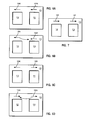
- FIG. 6 a schematic illustration of the pointer system employed in the invention will be described in detail whereby the dynamic linking of code segments in real time is effected.
- the first Fig. 6A is intended to illustrate the beginning of a sequence wherein the ACPA 24 is executing code resident in the left buffer 112. At this stage each time the ACPA 24 loops through this code it is obtaining a current pointer 120 which points to the address space wherein the code resident in the buffer 112 is executing.
- the host CPU 22 is of course executing code associated with the CPU asynchronously.
- the host will first cause a copy of this address (i.e. the address the current pointer 120 is point to) to be made.
- the host can of course make such a copy of the address associated with the current pointer 120 because the location of the pointers will be at known common addresses shared both by the DSP 26 and the host CPU 22, e.g. this is a tightly coupled co-processing system.
- a "next" pointer 122 is provided in the memory system 110.
- This "next" pointer is a pointer which indicates to the DSP, when it has completed a loop through the code in a given buffer 112 or 114, the address location of precisely where it should begin executing code of a module the next time through, i.e. the next time it loops through the upper branch point of the system 110.
- the next pointer 122 when the DSP is in the middle of executing the code of the module contained in buffer 112, the next pointer 122 will be pointing to the left indicating that at that time if execution were to continue through the buffer 112 and loop back to the top the left buffer 112 should continue to be executed.
- the host When the host, in asynchronously executing its own code, has determined that this next module is necessary for the DSP to commence executing, it first copies pointer 120C to pointer 133N (Fig. 6B). Then the host will begin filling the right buffer 114 with the new module. As long as the host is continuing to fill this buffer 114 with the code of the new function or module, it will be noted that the current pointer 120C and copy thereof 133N in Fig. 6B will continue to point to the address location of the beginning of the left buffer 112 thereby informing the DSP 26 to execute this code contained in the left buffer 112.
- this current pointer 120C or 133N is serving the function of informing the host CPU 22 not to write code into the left buffer 112 since the DSP 26 is still executing this code, i.e. the current pointer is pointing to the address of the start of the DSP code currently being executed and looped through.
- the pointer 133N is reversed (shown now as pointer 132N, Figs. 6C and 6D).
- the DSP 26 has thereby executed the remainder of the code in the buffer 112 for the last time and reaches a branch point associated with the pointers as represented by the top of the system 110, the next pointer 132N (Fig. 6C) now read by the DSP 26 will thus be pointing to the code in the right buffer 114. The DSP will not copy this pointer 132N to the current pointer 134C.
- this current pointer 134C is now informing the host CPU 32 not to write code for yet additional function or modules into the right buffer 114 since the DSP 26 is now currently executing and looping on the code of the modules contained in the right buffer 114. From the foregoing it will be appreciated that the current pointer is thus pointing to the address of the buffer the DSP 26 branched to the last time it looped through code in one of the buffers. In contrast the next pointer is pointing to the address of the buffer where the DSP 26 will be executing code on the next time through the system 110.
- First block 150 is intended to represent arbitrarily a starting point in the process wherein the DSP 26 is executing a first DSP module resident in the buffer 112. At the point as shown by block 152, the current pointer 120 of Fig. 6A is pointing to the starting address location of the DSP code resident in this left buffer 112.
- next pointer 122N of Fig. 6A is also pointing to this left buffer 112.
- a host program will indicate execution of a second DSP module is required other than that presently in the buffer 112 undergoing current execution. This is reflected in the block 156 of Fig. 8.
- the host reading current pointer 120C which points to the left buffer 112, knows that the DSP is currently continuing to execute code in buffer 112.
- the host copies the current pointer 120C to the next pointer as pointer 133N, block 160, which is also pointing to block 160, which is also pointing to buffer 112, and then starts filling buffer 114 with the new modules' code (shown at block 158).
- next pointer 133N Fig. 6B
- Fig. 6C next pointer 132N which now points to the thus completely filled right buffer 114.
- the DSP 26 may now commence execution of the code in this buffer 114 during the next cycle through code in the buffers. This is represented at block 166 and block 167.
- block 168 indicate that upon a next request for yet an additional new module to be executed by the DSP, the mirror image or opposite of the just-described process will continue, wherein the host will begin re-filling buffer 112 while the DSP is executing buffer 114 code.
- the DSP in accordance with the pointer reversal in the manner previously described, will again commence executing this code in buffer 112.
Landscapes
- Engineering & Computer Science (AREA)
- Software Systems (AREA)
- Theoretical Computer Science (AREA)
- General Engineering & Computer Science (AREA)
- Physics & Mathematics (AREA)
- General Physics & Mathematics (AREA)
- Acoustics & Sound (AREA)
- Multimedia (AREA)
- Electrophonic Musical Instruments (AREA)
- Multi Processors (AREA)
- Memory System Of A Hierarchy Structure (AREA)
- Complex Calculations (AREA)
Applications Claiming Priority (2)
| Application Number | Priority Date | Filing Date | Title |
|---|---|---|---|
| US60812690A | 1990-11-01 | 1990-11-01 | |
| US608126 | 1990-11-01 |
Publications (1)
| Publication Number | Publication Date |
|---|---|
| EP0483970A1 true EP0483970A1 (en) | 1992-05-06 |
Family
ID=24435152
Family Applications (1)
| Application Number | Title | Priority Date | Filing Date |
|---|---|---|---|
| EP91308794A Ceased EP0483970A1 (en) | 1990-11-01 | 1991-09-26 | Dynamically linking code segments in a multiprocessor system |
Country Status (10)
| Country | Link |
|---|---|
| US (1) | US5539896A (ja) |
| EP (1) | EP0483970A1 (ja) |
| JP (1) | JP3203701B2 (ja) |
| CZ (1) | CZ9300787A3 (ja) |
| HU (1) | HU215862B (ja) |
| IL (1) | IL99744A (ja) |
| PL (1) | PL166975B1 (ja) |
| SK (1) | SK41393A3 (ja) |
| WO (1) | WO1992008192A1 (ja) |
| ZA (1) | ZA918427B (ja) |
Cited By (8)
| Publication number | Priority date | Publication date | Assignee | Title |
|---|---|---|---|---|
| WO1994010628A1 (en) * | 1992-10-30 | 1994-05-11 | Tao Systems Ltd. | Data processing system and operating system |
| WO1997036283A1 (en) * | 1996-03-25 | 1997-10-02 | Advanced Micro Devices, Inc. | Computer system and method for performing wavetable music synthesis |
| US5809342A (en) * | 1996-03-25 | 1998-09-15 | Advanced Micro Devices, Inc. | Computer system and method for generating delay-based audio effects in a wavetable music synthesizer which stores wavetable data in system memory |
| WO2000000887A1 (en) * | 1998-06-30 | 2000-01-06 | Intergraph Corporation | Method and apparatus for transporting information to a graphic accelerator card |
| US6078945A (en) * | 1995-06-21 | 2000-06-20 | Tao Group Limited | Operating system for use with computer networks incorporating two or more data processors linked together for parallel processing and incorporating improved dynamic load-sharing techniques |
| EP1158405A1 (fr) * | 2000-05-23 | 2001-11-28 | Thales | Système et méthode de gestion d'une architecture multi-ressources |
| WO2004042591A1 (en) * | 2002-11-05 | 2004-05-21 | Koninklijke Philips Electronics N.V. | Data processing apparatus with address redirection in response to periodic address patterns |
| WO2020036879A1 (en) * | 2018-08-13 | 2020-02-20 | Cisco Technology, Inc. | In situ triggered function as a service within a service mesh |
Families Citing this family (36)
| Publication number | Priority date | Publication date | Assignee | Title |
|---|---|---|---|---|
| US5253275A (en) | 1991-01-07 | 1993-10-12 | H. Lee Browne | Audio and video transmission and receiving system |
| AU4219693A (en) * | 1992-09-30 | 1994-04-14 | Apple Computer, Inc. | Inter-task buffer and connections |
| US5949891A (en) * | 1993-11-24 | 1999-09-07 | Intel Corporation | Filtering audio signals from a combined microphone/speaker earpiece |
| JP3171361B2 (ja) * | 1994-05-06 | 2001-05-28 | ヤマハ株式会社 | Dspプログラミング装置 |
| US6163793A (en) * | 1994-08-05 | 2000-12-19 | Intel Corporation | Method and apparatus for using a driver program executing on a host processor to control the execution of code on an auxiliary processor |
| US5619731A (en) * | 1994-09-23 | 1997-04-08 | Ardent Teleproductions, Inc. | Interactive music CD and data |
| US5685005A (en) * | 1994-10-04 | 1997-11-04 | Analog Devices, Inc. | Digital signal processor configured for multiprocessing |
| US5671446A (en) * | 1995-03-16 | 1997-09-23 | Apple Computer, Inc. | Method and apparatus for atomically accessing a queue in a memory structure where LIFO is converted to FIFO |
| US5696990A (en) * | 1995-05-15 | 1997-12-09 | Nvidia Corporation | Method and apparatus for providing improved flow control for input/output operations in a computer system having a FIFO circuit and an overflow storage area |
| GB2301003B (en) * | 1995-05-19 | 2000-03-01 | Sony Uk Ltd | Audio mixing console |
| US5799314A (en) * | 1995-06-30 | 1998-08-25 | Sun Microsystems, Inc. | System and method of controlling mapping of data buffers for heterogenous programs in digital computer system |
| US5909702A (en) * | 1995-09-29 | 1999-06-01 | Intel Corporation | Memory address translations for programs code execution/relocation |
| JP3087638B2 (ja) * | 1995-11-30 | 2000-09-11 | ヤマハ株式会社 | 音楽情報処理システム |
| US5819067A (en) * | 1996-02-23 | 1998-10-06 | Advanced Micro Devices, Inc. | Computer system configured to translate a computer program into a second computer program prior to executing the computer program |
| US6031916A (en) * | 1996-02-28 | 2000-02-29 | Kabushiki Kaisha Kawai Gakki Seisakusho | Sound effect adding device using DSP |
| US5890013A (en) * | 1996-09-30 | 1999-03-30 | Intel Corporation | Paged memory architecture for a single chip multi-processor with physical memory pages that are swapped without latency |
| JP3747584B2 (ja) * | 1996-10-18 | 2006-02-22 | ヤマハ株式会社 | 端末装置の機能拡張方法及びホストコンピュータ並びに端末装置 |
| US6453409B1 (en) * | 1996-11-07 | 2002-09-17 | Yamaha Corporation | Digital signal processing system |
| US6308253B1 (en) * | 1999-03-31 | 2001-10-23 | Sony Corporation | RISC CPU instructions particularly suited for decoding digital signal processing applications |
| AU756842B2 (en) | 2000-08-29 | 2003-01-23 | Hoya Corporation | Optical element having antireflection film |
| JP2002207708A (ja) * | 2001-01-12 | 2002-07-26 | Mitsubishi Electric Corp | 演算装置 |
| EP1293895A3 (en) * | 2001-09-14 | 2006-01-25 | Ricoh Company, Ltd. | Program execution apparatus, method for creating an executable program and address solution method |
| US7174548B2 (en) * | 2001-10-15 | 2007-02-06 | Intel Corporation | Managing firmware download |
| US7546451B1 (en) * | 2002-06-19 | 2009-06-09 | Finisar Corporation | Continuously providing instructions to a programmable device |
| US6996699B2 (en) * | 2002-09-10 | 2006-02-07 | Microsoft Corporation | Secondary processor execution kernel framework |
| JP4542308B2 (ja) * | 2002-12-16 | 2010-09-15 | 株式会社ソニー・コンピュータエンタテインメント | 信号処理用デバイス及び情報処理機器 |
| JP4837247B2 (ja) * | 2003-09-24 | 2011-12-14 | パナソニック株式会社 | プロセッサ |
| US7487498B2 (en) * | 2003-11-12 | 2009-02-03 | Microsoft Corporation | Strategy for referencing code resources |
| US7266804B2 (en) | 2004-02-20 | 2007-09-04 | Microsoft Corporation | Strategy for selectively making non-public resources of one assembly visible to another |
| US7610200B2 (en) * | 2004-08-30 | 2009-10-27 | Lsi Corporation | System and method for controlling sound data |
| US8489783B2 (en) * | 2007-01-03 | 2013-07-16 | Apple Inc. | Multi buffer asynchronous scheme for processing incoming information |
| JP5099133B2 (ja) * | 2007-06-20 | 2012-12-12 | 富士通株式会社 | 処理装置 |
| US8041848B2 (en) * | 2008-08-04 | 2011-10-18 | Apple Inc. | Media processing method and device |
| US9250858B2 (en) * | 2013-02-20 | 2016-02-02 | International Business Machines Corporation | Dual-buffer serialization and consumption of variable-length data records produced by multiple parallel threads |
| EP2840503A1 (de) * | 2013-08-22 | 2015-02-25 | Continental Automotive GmbH | Verfahren zum Betreiben eines Pufferspeichers einer Datenverarbeitungsanlage und Datenverarbeitungsanlage |
| US20150363437A1 (en) * | 2014-06-17 | 2015-12-17 | Ims Health Incorporated | Data collection and cleaning at source |
Citations (1)
| Publication number | Priority date | Publication date | Assignee | Title |
|---|---|---|---|---|
| DE3610155A1 (de) * | 1986-03-26 | 1987-10-08 | Joachim Bauer | Mehrprozessorsystem fuer paralleles schreiben und lesen von informationen |
Family Cites Families (18)
| Publication number | Priority date | Publication date | Assignee | Title |
|---|---|---|---|---|
| US4298954A (en) * | 1979-04-30 | 1981-11-03 | International Business Machines Corporation | Alternating data buffers when one buffer is empty and another buffer is variably full of data |
| US4333143A (en) * | 1979-11-19 | 1982-06-01 | Texas Instruments | Input process sequence controller |
| JPS57191764A (en) * | 1981-05-21 | 1982-11-25 | Nec Corp | Storage device |
| US4562436A (en) * | 1982-07-16 | 1985-12-31 | At&T Bell Laboratories | Data communication network |
| US4897780A (en) * | 1984-10-09 | 1990-01-30 | Wang Laboratories, Inc. | Document manager system for allocating storage locations and generating corresponding control blocks for active documents in response to requests from active tasks |
| US4658351A (en) * | 1984-10-09 | 1987-04-14 | Wang Laboratories, Inc. | Task control means for a multi-tasking data processing system |
| US4667286A (en) * | 1984-12-20 | 1987-05-19 | Advanced Micro Devices, Inc. | Method and apparatus for transferring data between a disk and a central processing unit |
| US4841437A (en) * | 1985-09-18 | 1989-06-20 | Lp Com | System architecture for a test apparatus having primary and dependent processors |
| US4694426A (en) * | 1985-12-20 | 1987-09-15 | Ncr Corporation | Asynchronous FIFO status circuit |
| US5133062A (en) * | 1986-03-06 | 1992-07-21 | Advanced Micro Devices, Inc. | RAM buffer controller for providing simulated first-in-first-out (FIFO) buffers in a random access memory |
| US4791629A (en) * | 1986-06-02 | 1988-12-13 | Ibm Corporation | Communications switching system |
| US4791489A (en) * | 1987-03-06 | 1988-12-13 | Michael Polatnick | General purpose video special effects system and method therefor |
| US5163132A (en) * | 1987-09-24 | 1992-11-10 | Ncr Corporation | Integrated controller using alternately filled and emptied buffers for controlling bi-directional data transfer between a processor and a data storage device |
| US4991169A (en) * | 1988-08-02 | 1991-02-05 | International Business Machines Corporation | Real-time digital signal processing relative to multiple digital communication channels |
| US5247678A (en) * | 1989-10-12 | 1993-09-21 | Texas Instruments Incorporated | Load time linker for software used with a multiprocessor system |
| US5167028A (en) * | 1989-11-13 | 1992-11-24 | Lucid Corporation | System for controlling task operation of slave processor by switching access to shared memory banks by master processor |
| JPH03180933A (ja) * | 1989-12-08 | 1991-08-06 | Matsushita Electric Ind Co Ltd | スタックメモリ |
| US5150456A (en) * | 1990-08-06 | 1992-09-22 | Elite High Technology, Inc. | Graphic image printing system and method |
-
1991
- 1991-08-14 JP JP22887091A patent/JP3203701B2/ja not_active Expired - Fee Related
- 1991-09-26 EP EP91308794A patent/EP0483970A1/en not_active Ceased
- 1991-10-15 IL IL9974491A patent/IL99744A/en not_active IP Right Cessation
- 1991-10-22 ZA ZA918427A patent/ZA918427B/xx unknown
- 1991-10-29 HU HU9301263A patent/HU215862B/hu unknown
- 1991-10-29 WO PCT/EP1991/002036 patent/WO1992008192A1/en not_active Ceased
- 1991-10-29 PL PL91298936A patent/PL166975B1/pl not_active IP Right Cessation
- 1991-10-29 SK SK41393A patent/SK41393A3/sk unknown
- 1991-10-29 CZ CZ1993787A patent/CZ9300787A3/cs unknown
-
1994
- 1994-01-03 US US08/176,337 patent/US5539896A/en not_active Expired - Fee Related
Patent Citations (1)
| Publication number | Priority date | Publication date | Assignee | Title |
|---|---|---|---|---|
| DE3610155A1 (de) * | 1986-03-26 | 1987-10-08 | Joachim Bauer | Mehrprozessorsystem fuer paralleles schreiben und lesen von informationen |
Non-Patent Citations (3)
| Title |
|---|
| Inspec. Abstract acc. no. 91:3967221, Inspec (IEE)(London, GB). Truax, B.: " Chaotic nonlinear system and digital synthesis: an exploratory study ". & Proc. ICMC Glasgow, 10 Sep 1990, p100-103. Inspec doc. nr: A911108211, B91059244, C91061513. * |
| Inspec. Abstract acc.no. 88:3230295. Inspec IEE (London, GB). Roads, C.: " Introduction to granular synthesis". & Computer Music Journal (Summer 1988), Vol. 12, No. 2, p11-13. Inspec doc. nr.: B88067610 * |
| Inspec. Abstract acc.no. 91:3967222, Inspec IEE (London, GB). Truax. B.: "Time-shifting of sampled sound with a real-time granulation technique". & Proc. ICMC Glasgow, 10 Sep 1990, p104-107. Inspec doc nr.: B91059245, C91061514 * |
Cited By (17)
| Publication number | Priority date | Publication date | Assignee | Title |
|---|---|---|---|---|
| US5930511A (en) * | 1992-10-30 | 1999-07-27 | Tao Group Limited | Operating system for use with computer networks incorporating one or more data processors linked together for parallel processing and incorporating improved dynamic binding and/or load-sharing techniques |
| GB2286269A (en) * | 1992-10-30 | 1995-08-09 | Tao Systems Ltd | Data processing system and operating system |
| GB2286269B (en) * | 1992-10-30 | 1996-06-12 | Tao Systems Ltd | Data processing system and operating system |
| AU679686B2 (en) * | 1992-10-30 | 1997-07-10 | Tao Group Limited | Data processing system and operating system |
| WO1994010628A1 (en) * | 1992-10-30 | 1994-05-11 | Tao Systems Ltd. | Data processing system and operating system |
| KR100419108B1 (ko) * | 1992-10-30 | 2004-05-20 | 타오 그룹 리미티드 | 데이터처리시스템 |
| US6078945A (en) * | 1995-06-21 | 2000-06-20 | Tao Group Limited | Operating system for use with computer networks incorporating two or more data processors linked together for parallel processing and incorporating improved dynamic load-sharing techniques |
| WO1997036283A1 (en) * | 1996-03-25 | 1997-10-02 | Advanced Micro Devices, Inc. | Computer system and method for performing wavetable music synthesis |
| US5809342A (en) * | 1996-03-25 | 1998-09-15 | Advanced Micro Devices, Inc. | Computer system and method for generating delay-based audio effects in a wavetable music synthesizer which stores wavetable data in system memory |
| US5763801A (en) * | 1996-03-25 | 1998-06-09 | Advanced Micro Devices, Inc. | Computer system and method for performing wavetable music synthesis which stores wavetable data in system memory |
| WO2000000887A1 (en) * | 1998-06-30 | 2000-01-06 | Intergraph Corporation | Method and apparatus for transporting information to a graphic accelerator card |
| EP1158405A1 (fr) * | 2000-05-23 | 2001-11-28 | Thales | Système et méthode de gestion d'une architecture multi-ressources |
| FR2809508A1 (fr) * | 2000-05-23 | 2001-11-30 | Thomson Csf | Systeme et methode de gestion d'une architecture multi-ressources |
| US7222346B2 (en) | 2000-05-23 | 2007-05-22 | Thales | System and method for the management of a multiple-resource architecture |
| WO2004042591A1 (en) * | 2002-11-05 | 2004-05-21 | Koninklijke Philips Electronics N.V. | Data processing apparatus with address redirection in response to periodic address patterns |
| WO2020036879A1 (en) * | 2018-08-13 | 2020-02-20 | Cisco Technology, Inc. | In situ triggered function as a service within a service mesh |
| US11716264B2 (en) | 2018-08-13 | 2023-08-01 | Cisco Technology, Inc. | In situ triggered function as a service within a service mesh |
Also Published As
| Publication number | Publication date |
|---|---|
| PL166975B1 (pl) | 1995-07-31 |
| HU215862B (hu) | 1999-03-29 |
| IL99744A (en) | 1995-05-26 |
| HU9301263D0 (en) | 1993-08-30 |
| CZ9300787A3 (cs) | 2002-07-17 |
| SK41393A3 (en) | 1993-07-07 |
| WO1992008192A1 (en) | 1992-05-14 |
| ZA918427B (en) | 1992-08-26 |
| US5539896A (en) | 1996-07-23 |
| JPH04289955A (ja) | 1992-10-14 |
| JP3203701B2 (ja) | 2001-08-27 |
| HUT65534A (en) | 1994-06-28 |
Similar Documents
| Publication | Publication Date | Title |
|---|---|---|
| US5539896A (en) | Method and apparatus for dynamically linking code segments in real time in a multiprocessor computing system employing dual buffered shared memory | |
| EP0241946B1 (en) | Information processing system | |
| US6292854B1 (en) | Method and apparatus for providing high quality audio in a computer system | |
| US5404511A (en) | Compact disc player with fragment memory management | |
| Jaffe et al. | An overview of the sound and music kits for the NeXT computer | |
| US5852729A (en) | Code segment replacement apparatus and real time signal processor using same | |
| US6473847B1 (en) | Memory management method for use in computer system | |
| JPH09179556A (ja) | 楽音生成方法および装置 | |
| GB2269247A (en) | Interfacing an IC memory card to a central processing unit of a computer | |
| KR100302030B1 (ko) | 음성정보처리장치 | |
| US5956680A (en) | Virtual audio generation and capture in a computer | |
| US6545210B2 (en) | Musical sound generator | |
| Savell | The EMU10K1 digital audio processor | |
| JPS6118995A (ja) | 演奏システム | |
| JP3005987B2 (ja) | デジタル信号処理装置 | |
| JPH09319373A (ja) | 楽音形成装置 | |
| Jaffe et al. | Sound and Music on the NeXT Computer™ | |
| KR0167304B1 (ko) | 음원발생기 | |
| JPH10124059A (ja) | 楽音発生方法および記憶媒体 | |
| JPH0713861A (ja) | Cpuインタフェース装置 | |
| JPH02105237A (ja) | 順編成ファイルのデータ更新方式 | |
| JP2014112198A (ja) | 音発生装置 | |
| Jaffe et al. | for the NeXT Computer | |
| Wuorinen | Computer Music Journal: Volume IV, 1-4 | |
| JPH10124051A (ja) | 曲データ加工方法、加工後曲データ再生方法および記憶媒体 |
Legal Events
| Date | Code | Title | Description |
|---|---|---|---|
| PUAI | Public reference made under article 153(3) epc to a published international application that has entered the european phase |
Free format text: ORIGINAL CODE: 0009012 |
|
| AK | Designated contracting states |
Kind code of ref document: A1 Designated state(s): DE FR GB |
|
| 17P | Request for examination filed |
Effective date: 19920917 |
|
| 17Q | First examination report despatched |
Effective date: 19961001 |
|
| GRAG | Despatch of communication of intention to grant |
Free format text: ORIGINAL CODE: EPIDOS AGRA |
|
| STAA | Information on the status of an ep patent application or granted ep patent |
Free format text: STATUS: THE APPLICATION HAS BEEN REFUSED |
|
| 18R | Application refused |
Effective date: 19980803 |