EP0487100A1 - Dispositif de suivi d'un véhicule - Google Patents
Dispositif de suivi d'un véhicule Download PDFInfo
- Publication number
- EP0487100A1 EP0487100A1 EP91119955A EP91119955A EP0487100A1 EP 0487100 A1 EP0487100 A1 EP 0487100A1 EP 91119955 A EP91119955 A EP 91119955A EP 91119955 A EP91119955 A EP 91119955A EP 0487100 A1 EP0487100 A1 EP 0487100A1
- Authority
- EP
- European Patent Office
- Prior art keywords
- window
- distance
- image
- vehicle
- preceding vehicle
- Prior art date
- Legal status (The legal status is an assumption and is not a legal conclusion. Google has not performed a legal analysis and makes no representation as to the accuracy of the status listed.)
- Granted
Links
Images



Classifications
-
- G—PHYSICS
- G01—MEASURING; TESTING
- G01S—RADIO DIRECTION-FINDING; RADIO NAVIGATION; DETERMINING DISTANCE OR VELOCITY BY USE OF RADIO WAVES; LOCATING OR PRESENCE-DETECTING BY USE OF THE REFLECTION OR RERADIATION OF RADIO WAVES; ANALOGOUS ARRANGEMENTS USING OTHER WAVES
- G01S11/00—Systems for determining distance or velocity not using reflection or reradiation
- G01S11/12—Systems for determining distance or velocity not using reflection or reradiation using electromagnetic waves other than radio waves
Definitions
- the present invention relates to a vehicle following apparatus which enables a vehicle to automatically follow a preceding vehicle running ahead thereof while optically measuring the distance thereto.
- Examples of an optical distance detecting apparatus utilizing image sensors are known from Japanese Patent Publication Nos. 63-38085 and 63-46363.
- the apparatuses disclosed therein commonly have a pair of first and second parallel optical systems having two convex lenses 101, 102 disposed in a horizontally aligned relation at a prescribed distance L away from each other, as shown in Fig. 5.
- a pair of separate image sensors 103, 104 are horizontally disposed at focal points of the lenses 101, 102 at a distance f from the locations of corresponding lenses 101, 102, respectively, for generating respective image signals to a common signal processor 120.
- the distance to an object is measured on the basis of a comparison between a pair of images sensed by the pair of optical systems including the image sensors. Accordingly, in cases where this apparatus is mounted on a vehicle for measuring the distance to a preceding vehicle, it is difficult for the driver to precisely determine to which vehicle the distance measurement is being effected if there are a plurality of preceding vehicles.
- the present invention is intended to overcome the above-mentioned problems encountered with the above-mentioned prior art.
- An object of the invention is to provide a novel and improved vehicle following apparatus which is able to continuously or successively measure, once a target vehicle to be followed is determined, the distance to the target vehicle in a stable and reliable manner even if the subject vehicle, on which the apparatus is mounted, is momentarily caused to move in the vertical or horizontal direction with respect to the target vehicle.
- Another object of the invention is to provide a novel and improved vehicle following apparatus in which the driver can readily see to which vehicle the distance is being measured even if there are a plurality of preceding vehicles.
- a vehicle following apparatus with a distance measuring function
- the apparatus comprising: a pair of first and second image sensors including a pair of optical systems disposed at a predetermined distance from each other for optically sensing a plurality of objects including a preceding vehicle running ahead of a subject vehicle, on which the vehicle following apparatus is mounted; a first memory for storing the images of the objects sensed by the first image sensor as first image signals; a second memory for storing the images of the objects sensed by the second image sensor as second image signals; a display with a screen for displaying the images of the objects as sensed by the image sensors on the screen; image following means for defining on the screen of the display a first window containing therein an image of a preceding vehicle running ahead of the subject vehicle, and a second window around the first widow for catching the background of the preceding vehicle, the image following means being operable to control the first window in such a manner as to automatically follow the image of the preceding vehicle; distance
- the image following means defines the second window at a location adjacent and above the first window, and the window position correcting means moves the position of the first window in a vertical direction depending upon whether the distance to the object in the first window is equal to or greater than the distance to the object in the second window.
- the window position correcting means moves the position of the first window in an upward direction if the distance to the object in the first window is equal to the distance to the object in the second window, or in a downward direction if the distance to the object in the first window is greater than the distance to the object in the second window.
- the image following means defines the second window at a location horizontally adjacent one side of the first window, and the window position correcting means moves the position of the first window in a horizontal direction depending upon whether the distance to the object in the first window is equal to or greater than the distance to the object in the second window.
- the window position correcting means moves the position of the first window in a horizontal direction toward the second window if the distance to the object in the first window is equal to the distance to the object in the second window, or in a direction away from the second window if the distance to the object in the first window is greater than the distance to the object in the second window.
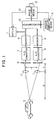
- Fig. 1 illustrates, in a block diagram, the schematic arrangement of a vehicle following apparatus which is constructed in accordance with the principles of the invention and which is mounted on a vehicle for the purpose of following a preceding vehicle while measuring the distance thereto.
- the apparatus illustrated includes a pair of first and second parallel optical systems having two convex lenses 1, 2 disposed in a vertically aligned relation at a prescribed distance L away from each other, and a pair of separate first and second (e.g., upper and lower) image sensors 3, 4 which are vertically or otherwise disposed at focal points of the lenses 1, 2, respectively, at a distance f from the locations of the corresponding lenses 1, 2 for generating first and second image signals in the form of analog signals representative of a two-dimensional image, which are input to a pair of corresponding first and second analog-to-digital (A/D) converters 6, 7.
- the outputs of the A/D converters 6, 7 are input to a pair of corresponding first and second memories 8, 9 and stored therein.
- a microcomputer 10 which acts as a distance calculating means and an obstacle discriminating means as claimed of the invention, performs data transfer with the memories 8, 9 so that it makes various calculations and determinations based on the data stored in the memories 8, 9.
- a display 11 having a screen is connected to the first and second memories 8, 9 and the microcomputer 10 for displaying the images of objects sensed by the first or second image sensor 8, 9 on the screen. The operation of the display 11 is controlled by the microcomputer 10.
- An image following means 12 is connected to the microcomputer 10 for following the image 5a of a preceding vehicle 5 and defining on the screen of the display 11 a first window 15 for use in following the image 5a of the preceding vehicle 5, as well as a second window 16 in the vicinity or around the first window 15, which is used for proper adjustment in the position of the first window 15 relative to the preceding vehicle image 5a.
- An instruction switch 13 is connected to the image following means 12 so that it is operated by the driver to instruct the image following means 12 to start following a preceding vehicle.
- a window position correcting means 14 is connected to the microcomputer 10 and the image following means 13 so that on the basis of information about the distances to objects caught by the first and second windows 15, 16, it serves to properly correct the position of the first window 15 as set by the image following means 12.
- the driver operates to turn the instruction switch 13 on whereby the vehicle of the driver is controlled to automatically follow the preceding vehicle 5 while catching the image 5a thereof in the first window 15 without fail irrespective of any movement thereof.
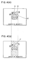
- the second window 16, which is defined, in the illustrated embodiment, on the screen 11 just above the first window 15 in vertical alignment therewith, also automatically accompanies the movement of the first window 15.
- the microcomputer 10 reads out from the second memory 9 image signals or picture element (pixel) signals within the first window 15 following the image 5a of the preceding vehicle 5, and makes them as reference image or pixel signals.
- the microcomputer 10 selects, from the first memory 8 storing therein pixel signals sensed by the first or lower image sensor 3, an area corresponding vertically to the first window 15, and calculates a sum of the absolute values of differences or deviations between the pixel signals thus selected from the first memory 8 and the corresponding reference pixel signals by successively shifting the pixel signals in the first memory 8 one pixel by one pixel.
- the position of an image stored in the first memory 8, which provides the best match with the reference image 5a in the first window 15, is determined by successively shifting the pixel signals selected from the first memory 8 one pixel by one pixel.
- the area in the first memory 8 relating to or to be searched for the above calculation is a vertical band area 17 which corresponds vertically to or is in vertical alignment with the position of the first window 15 stored in the second memory 9.
- the microcomputer 10 selects from the first memory 8, which stores therein the image or pixel signals sensed by the first or lower image sensor 3, a vertical band area 17 corresponding vertically to or aligned vertically with the second window 16, and calculates a total sum of the absolute values of differences or deviations between the corresponding upper and lower image or pixel signals in the second and first memories 9, 8 by successively shifting image or pixel signals within the area 17 with respect to the above defined reference image or pixel signals one pixel by one pixel, to provide the position of an image in the area 17 which best matches the image 18 in the second window 16.
- the information on the inter-vehicle distance R i.e., the distance to the preceding vehicle 5 caught by the first window 15 as well as the distance A to the object 18 (which is a mountain in the illustrated embodiment) caught by the second window 16 and calculated in the above manner is successively input to the window position correcting means 14 where the inter-vehicle distance R and the distance A to the object 18 are compared with each other.
- the microcomputer 10 determines that the image 18 of the object in the second or upper window 16 is not a portion of the image 5a of the preceding vehicle 5, and that the first window 15 may be positioned too high with respect to the preceding vehicle image 5a.
- the window position correcting means 14 operates to displace the position of the first window 15 in a downward direction relative to the preceding vehicle image 5a.
- a portion of the preceding vehicle image 5a comes in the second window 16, so the distance to the preceding vehicle 5 can be measured by the second window 16.
- the microcomputer 10 determines that the image 18 of the object in the second window 16 is a portion of the image 5a of the preceding vehicle 5, and that the first window 15 may be positioned too low with respect to the preceding vehicle image 5a. Accordingly, the window position correcting means 14 begins to displace the position of the first window 15 in an upward direction relative to the preceding vehicle image 5a, so that the image 5a of the preceding vehicle 5 entirely disappear from the second window 16, which then catches a background object 18 such as a mountain more distant from the subject vehicle than the preceding vehicle 5 in order to measure the distance A to the mountain 18. As a consequence, the distance A becomes greater than the inter-vehicle distance R.
- the first window 15 following the preceding vehicle image 5a is vertically moved in an automatic fashion so that the position of the first window 15 is prevented from any excessive vertical displacements with respect to the preceding vehicle image 5a, thus enabling the first window 15 to follow it in a most stable and reliable manner.
- the second window 16 is set at a location adjacent and above the first window 15 so as to prevent excessive vertical displacements thereof with respect to the preceding vehicle image 5a, it can be defined at any other location around the first window 15. For example, it can be set to the right or left of the first window 15 (or horizontally adjacent one side thereof) for the purpose of preventing any excessive lateral or sidewise displacement of the first window 15 relative to the preceding vehicle image 5a.
- first and second windows 15, 16 are not limited to those as described above but can arbitrarily be varied in accordance with an object to be followed or caught.
Landscapes
- Physics & Mathematics (AREA)
- Electromagnetism (AREA)
- Engineering & Computer Science (AREA)
- General Physics & Mathematics (AREA)
- Radar, Positioning & Navigation (AREA)
- Remote Sensing (AREA)
- Measurement Of Optical Distance (AREA)
- Image Processing (AREA)
- Traffic Control Systems (AREA)
Applications Claiming Priority (2)
| Application Number | Priority Date | Filing Date | Title |
|---|---|---|---|
| JP318919/90 | 1990-11-22 | ||
| JP2318919A JPH0827188B2 (ja) | 1990-11-22 | 1990-11-22 | 車間距離検出装置 |
Publications (2)
| Publication Number | Publication Date |
|---|---|
| EP0487100A1 true EP0487100A1 (fr) | 1992-05-27 |
| EP0487100B1 EP0487100B1 (fr) | 1995-02-08 |
Family
ID=18104441
Family Applications (1)
| Application Number | Title | Priority Date | Filing Date |
|---|---|---|---|
| EP91119955A Expired - Lifetime EP0487100B1 (fr) | 1990-11-22 | 1991-11-22 | Dispositif de suivi d'un véhicule |
Country Status (4)
| Country | Link |
|---|---|
| US (1) | US5187537A (fr) |
| EP (1) | EP0487100B1 (fr) |
| JP (1) | JPH0827188B2 (fr) |
| DE (1) | DE69107283T2 (fr) |
Cited By (3)
| Publication number | Priority date | Publication date | Assignee | Title |
|---|---|---|---|---|
| US9609289B2 (en) | 2004-04-15 | 2017-03-28 | Magna Electronics Inc. | Vision system for vehicle |
| US9643605B2 (en) | 2002-05-03 | 2017-05-09 | Magna Electronics Inc. | Vision system for vehicle |
| US10071676B2 (en) | 2006-08-11 | 2018-09-11 | Magna Electronics Inc. | Vision system for vehicle |
Families Citing this family (12)
| Publication number | Priority date | Publication date | Assignee | Title |
|---|---|---|---|---|
| JP2635246B2 (ja) * | 1991-08-28 | 1997-07-30 | 三菱電機株式会社 | 先行車追尾用車間距離検出装置 |
| US6822563B2 (en) | 1997-09-22 | 2004-11-23 | Donnelly Corporation | Vehicle imaging system with accessory control |
| US5877897A (en) | 1993-02-26 | 1999-03-02 | Donnelly Corporation | Automatic rearview mirror, vehicle lighting control and vehicle interior monitoring system using a photosensor array |
| JP3212218B2 (ja) * | 1994-05-26 | 2001-09-25 | 三菱電機株式会社 | 車両用障害物検出装置 |
| US5627510A (en) * | 1994-09-12 | 1997-05-06 | Yuan; Zhiping | Vehicular safety distance alarm system |
| US6891563B2 (en) | 1996-05-22 | 2005-05-10 | Donnelly Corporation | Vehicular vision system |
| US7655894B2 (en) | 1996-03-25 | 2010-02-02 | Donnelly Corporation | Vehicular image sensing system |
| US6225918B1 (en) | 1999-02-19 | 2001-05-01 | Bing Kam | Automatic warning signal system for vehicles |
| US6327219B1 (en) | 1999-09-29 | 2001-12-04 | Vi&T Group | Method and system for directing a following device toward a movable object |
| JP2009200713A (ja) * | 2008-02-20 | 2009-09-03 | Sony Corp | 画像処理装置、画像処理方法、プログラム |
| IL200921A (en) * | 2009-09-14 | 2016-05-31 | Israel Aerospace Ind Ltd | A robotic carry system for infantry and useful methods for the above purpose |
| CN115158210B (zh) * | 2022-06-15 | 2023-08-25 | 星河智联汽车科技有限公司 | 一种物体伸出车窗的监测方法、装置、设备及存储介质 |
Citations (3)
| Publication number | Priority date | Publication date | Assignee | Title |
|---|---|---|---|---|
| GB2202104A (en) * | 1987-02-13 | 1988-09-14 | Tecnomare Spa | Ranging by correlation |
| US4931937A (en) * | 1987-09-01 | 1990-06-05 | Aisin Seiki Kabushiki Kaisha | Distance detector mounted on vehicle |
| DE4006989A1 (de) * | 1989-03-07 | 1990-09-13 | Mitsubishi Electric Corp | Nachfuehrende abstandsmessvorrichtung |
Family Cites Families (4)
| Publication number | Priority date | Publication date | Assignee | Title |
|---|---|---|---|---|
| JPS6033352B2 (ja) * | 1980-02-19 | 1985-08-02 | 三菱電機株式会社 | 画像目標追尾装置 |
| JPS5822975A (ja) * | 1981-08-03 | 1983-02-10 | Mitsubishi Electric Corp | 相関画像追尾装置 |
| JPS58196412A (ja) * | 1982-05-12 | 1983-11-15 | Mitsubishi Electric Corp | 距離計測器 |
| JPS60120273A (ja) * | 1983-12-02 | 1985-06-27 | Tech Res & Dev Inst Of Japan Def Agency | 目標位置検出装置 |
-
1990
- 1990-11-22 JP JP2318919A patent/JPH0827188B2/ja not_active Expired - Fee Related
-
1991
- 1991-11-20 US US07/795,070 patent/US5187537A/en not_active Expired - Lifetime
- 1991-11-22 DE DE69107283T patent/DE69107283T2/de not_active Expired - Fee Related
- 1991-11-22 EP EP91119955A patent/EP0487100B1/fr not_active Expired - Lifetime
Patent Citations (3)
| Publication number | Priority date | Publication date | Assignee | Title |
|---|---|---|---|---|
| GB2202104A (en) * | 1987-02-13 | 1988-09-14 | Tecnomare Spa | Ranging by correlation |
| US4931937A (en) * | 1987-09-01 | 1990-06-05 | Aisin Seiki Kabushiki Kaisha | Distance detector mounted on vehicle |
| DE4006989A1 (de) * | 1989-03-07 | 1990-09-13 | Mitsubishi Electric Corp | Nachfuehrende abstandsmessvorrichtung |
Non-Patent Citations (2)
| Title |
|---|
| PATENT ABSTRACTS OF JAPAN vol. 7, no. 96 (P-193)(1241) 22 April 1983 & JP-A-58 022 975 ( MITSUBISHI DENKI ) 10 February 1983 * |
| PATENT ABSTRACTS OF JAPAN vol. 9, no. 276 (P-402)(1999) 2 November 1985 & JP-A-60 120 273 ( BOEICHO GIJUTSU KENKYU HONBU ) 27 June 1985 * |
Cited By (23)
| Publication number | Priority date | Publication date | Assignee | Title |
|---|---|---|---|---|
| US10118618B2 (en) | 2002-05-03 | 2018-11-06 | Magna Electronics Inc. | Vehicular control system using cameras and radar sensor |
| US9643605B2 (en) | 2002-05-03 | 2017-05-09 | Magna Electronics Inc. | Vision system for vehicle |
| US11203340B2 (en) | 2002-05-03 | 2021-12-21 | Magna Electronics Inc. | Vehicular vision system using side-viewing camera |
| US9834216B2 (en) | 2002-05-03 | 2017-12-05 | Magna Electronics Inc. | Vehicular control system using cameras and radar sensor |
| US10683008B2 (en) | 2002-05-03 | 2020-06-16 | Magna Electronics Inc. | Vehicular driving assist system using forward-viewing camera |
| US10351135B2 (en) | 2002-05-03 | 2019-07-16 | Magna Electronics Inc. | Vehicular control system using cameras and radar sensor |
| US10306190B1 (en) | 2004-04-15 | 2019-05-28 | Magna Electronics Inc. | Vehicular control system |
| US11503253B2 (en) | 2004-04-15 | 2022-11-15 | Magna Electronics Inc. | Vehicular control system with traffic lane detection |
| US11847836B2 (en) | 2004-04-15 | 2023-12-19 | Magna Electronics Inc. | Vehicular control system with road curvature determination |
| US10187615B1 (en) | 2004-04-15 | 2019-01-22 | Magna Electronics Inc. | Vehicular control system |
| US9609289B2 (en) | 2004-04-15 | 2017-03-28 | Magna Electronics Inc. | Vision system for vehicle |
| US10015452B1 (en) | 2004-04-15 | 2018-07-03 | Magna Electronics Inc. | Vehicular control system |
| US10462426B2 (en) | 2004-04-15 | 2019-10-29 | Magna Electronics Inc. | Vehicular control system |
| US9948904B2 (en) | 2004-04-15 | 2018-04-17 | Magna Electronics Inc. | Vision system for vehicle |
| US10735695B2 (en) | 2004-04-15 | 2020-08-04 | Magna Electronics Inc. | Vehicular control system with traffic lane detection |
| US10110860B1 (en) | 2004-04-15 | 2018-10-23 | Magna Electronics Inc. | Vehicular control system |
| US9736435B2 (en) | 2004-04-15 | 2017-08-15 | Magna Electronics Inc. | Vision system for vehicle |
| US11148583B2 (en) | 2006-08-11 | 2021-10-19 | Magna Electronics Inc. | Vehicular forward viewing image capture system |
| US11396257B2 (en) | 2006-08-11 | 2022-07-26 | Magna Electronics Inc. | Vehicular forward viewing image capture system |
| US10787116B2 (en) | 2006-08-11 | 2020-09-29 | Magna Electronics Inc. | Adaptive forward lighting system for vehicle comprising a control that adjusts the headlamp beam in response to processing of image data captured by a camera |
| US11623559B2 (en) | 2006-08-11 | 2023-04-11 | Magna Electronics Inc. | Vehicular forward viewing image capture system |
| US10071676B2 (en) | 2006-08-11 | 2018-09-11 | Magna Electronics Inc. | Vision system for vehicle |
| US11951900B2 (en) | 2006-08-11 | 2024-04-09 | Magna Electronics Inc. | Vehicular forward viewing image capture system |
Also Published As
| Publication number | Publication date |
|---|---|
| JPH04188014A (ja) | 1992-07-06 |
| US5187537A (en) | 1993-02-16 |
| JPH0827188B2 (ja) | 1996-03-21 |
| DE69107283D1 (de) | 1995-03-23 |
| EP0487100B1 (fr) | 1995-02-08 |
| DE69107283T2 (de) | 1995-07-13 |
Similar Documents
| Publication | Publication Date | Title |
|---|---|---|
| EP0496411B1 (fr) | Appareil pour estimer une distance pour véhicules | |
| KR930004880B1 (ko) | 추미식 차간거리 측정장치 | |
| US5187537A (en) | Vehicle following apparatus | |
| EP0510363B1 (fr) | Dispositif pour mesurer des distances | |
| US5424952A (en) | Vehicle-surroundings monitoring apparatus | |
| EP0473945A2 (fr) | Appareil de détection de la distance entre voitures | |
| JP2671615B2 (ja) | ガードレール検出装置 | |
| EP0465863A2 (fr) | Appareil et méthode de détermination de distance pour un véhicule | |
| US5257022A (en) | Method and apparatus for following a vehicle | |
| JP2800530B2 (ja) | 車間距離検出装置 | |
| US5381173A (en) | Inter-car distance detecting device for tracking a car running ahead | |
| EP0474067B1 (fr) | Appareil de détection de distance | |
| EP0546518A1 (fr) | Dispositif de mesure de la distance entre des véhicules | |
| EP0498416B1 (fr) | Dispositif détecteur de distance entre des véhicules | |
| EP0529558B1 (fr) | Dispositif de mesure de la distance entre véhicules | |
| JP2827682B2 (ja) | 車間距離検出装置 | |
| JP2560147B2 (ja) | 車間距離検出装置 | |
| JPH0754253B2 (ja) | 追尾式車間距離測定装置 | |
| JPH04313014A (ja) | 車間距離検出装置 | |
| JP2730682B2 (ja) | 画像処理装置 |
Legal Events
| Date | Code | Title | Description |
|---|---|---|---|
| PUAI | Public reference made under article 153(3) epc to a published international application that has entered the european phase |
Free format text: ORIGINAL CODE: 0009012 |
|
| AK | Designated contracting states |
Kind code of ref document: A1 Designated state(s): DE FR GB |
|
| 17P | Request for examination filed |
Effective date: 19920702 |
|
| 17Q | First examination report despatched |
Effective date: 19930910 |
|
| GRAA | (expected) grant |
Free format text: ORIGINAL CODE: 0009210 |
|
| AK | Designated contracting states |
Kind code of ref document: B1 Designated state(s): DE FR GB |
|
| REF | Corresponds to: |
Ref document number: 69107283 Country of ref document: DE Date of ref document: 19950323 |
|
| REG | Reference to a national code |
Ref country code: GB Ref legal event code: 727 |
|
| ET | Fr: translation filed | ||
| REG | Reference to a national code |
Ref country code: GB Ref legal event code: 727A |
|
| REG | Reference to a national code |
Ref country code: GB Ref legal event code: 727B |
|
| PLBE | No opposition filed within time limit |
Free format text: ORIGINAL CODE: 0009261 |
|
| STAA | Information on the status of an ep patent application or granted ep patent |
Free format text: STATUS: NO OPPOSITION FILED WITHIN TIME LIMIT |
|
| REG | Reference to a national code |
Ref country code: GB Ref legal event code: SP |
|
| 26N | No opposition filed | ||
| REG | Reference to a national code |
Ref country code: GB Ref legal event code: IF02 |
|
| PGFP | Annual fee paid to national office [announced via postgrant information from national office to epo] |
Ref country code: FR Payment date: 20051108 Year of fee payment: 15 |
|
| PGFP | Annual fee paid to national office [announced via postgrant information from national office to epo] |
Ref country code: GB Payment date: 20051116 Year of fee payment: 15 |
|
| PGFP | Annual fee paid to national office [announced via postgrant information from national office to epo] |
Ref country code: DE Payment date: 20051117 Year of fee payment: 15 |
|
| PG25 | Lapsed in a contracting state [announced via postgrant information from national office to epo] |
Ref country code: DE Free format text: LAPSE BECAUSE OF NON-PAYMENT OF DUE FEES Effective date: 20070601 |
|
| GBPC | Gb: european patent ceased through non-payment of renewal fee |
Effective date: 20061122 |
|
| REG | Reference to a national code |
Ref country code: FR Ref legal event code: ST Effective date: 20070731 |
|
| PG25 | Lapsed in a contracting state [announced via postgrant information from national office to epo] |
Ref country code: GB Free format text: LAPSE BECAUSE OF NON-PAYMENT OF DUE FEES Effective date: 20061122 |
|
| PG25 | Lapsed in a contracting state [announced via postgrant information from national office to epo] |
Ref country code: FR Free format text: LAPSE BECAUSE OF NON-PAYMENT OF DUE FEES Effective date: 20061130 |