EP0465863A2 - Appareil et méthode de détermination de distance pour un véhicule - Google Patents
Appareil et méthode de détermination de distance pour un véhicule Download PDFInfo
- Publication number
- EP0465863A2 EP0465863A2 EP91109711A EP91109711A EP0465863A2 EP 0465863 A2 EP0465863 A2 EP 0465863A2 EP 91109711 A EP91109711 A EP 91109711A EP 91109711 A EP91109711 A EP 91109711A EP 0465863 A2 EP0465863 A2 EP 0465863A2
- Authority
- EP
- European Patent Office
- Prior art keywords
- image signals
- window
- provisional
- symmetry
- distance
- Prior art date
- Legal status (The legal status is an assumption and is not a legal conclusion. Google has not performed a legal analysis and makes no representation as to the accuracy of the status listed.)
- Granted
Links
Images




Classifications
-
- G—PHYSICS
- G01—MEASURING; TESTING
- G01S—RADIO DIRECTION-FINDING; RADIO NAVIGATION; DETERMINING DISTANCE OR VELOCITY BY USE OF RADIO WAVES; LOCATING OR PRESENCE-DETECTING BY USE OF THE REFLECTION OR RERADIATION OF RADIO WAVES; ANALOGOUS ARRANGEMENTS USING OTHER WAVES
- G01S11/00—Systems for determining distance or velocity not using reflection or reradiation
- G01S11/12—Systems for determining distance or velocity not using reflection or reradiation using electromagnetic waves other than radio waves
-
- G—PHYSICS
- G01—MEASURING; TESTING
- G01S—RADIO DIRECTION-FINDING; RADIO NAVIGATION; DETERMINING DISTANCE OR VELOCITY BY USE OF RADIO WAVES; LOCATING OR PRESENCE-DETECTING BY USE OF THE REFLECTION OR RERADIATION OF RADIO WAVES; ANALOGOUS ARRANGEMENTS USING OTHER WAVES
- G01S17/00—Systems using the reflection or reradiation of electromagnetic waves other than radio waves, e.g. lidar systems
- G01S17/88—Lidar systems specially adapted for specific applications
- G01S17/93—Lidar systems specially adapted for specific applications for anti-collision purposes
- G01S17/931—Lidar systems specially adapted for specific applications for anti-collision purposes of land vehicles
-
- G—PHYSICS
- G06—COMPUTING OR CALCULATING; COUNTING
- G06V—IMAGE OR VIDEO RECOGNITION OR UNDERSTANDING
- G06V20/00—Scenes; Scene-specific elements
- G06V20/50—Context or environment of the image
- G06V20/56—Context or environment of the image exterior to a vehicle by using sensors mounted on the vehicle
Definitions
- the present invention relates to a distance detecting apparatus and method for a vehicle which successively measures the distance from a vehicle to a preceding vehicle running ahead thereof.
- FIG. 7 Some typical examples of such a distance detecting apparatus are disclosed in Japanese Patent Publication Nos. 63-38085 and 63-46363.
- the apparatuses disclosed therein commonly have a pair of first and second parallel optical systems having two convex lenses 101, 102 disposed in a horizontally aligned relation at a prescribed distance B away from each other, as shown in Fig. 7.
- a pair of separate image sensors 103, 104 are horizontally disposed at focal points of the lenses 101, 102 spaced a focal distance f from the locations of corresponding lenses 101, 102, respectively, for generating respective image signals representative of an object 105 such as a vehicle.
- a pair of A/D converters 106, 107 receive the image signals from the corresponding image sensors 103, 104 and convert them into digital signals which are then stored in a pair of corresponding memories 108, 109.
- a common microprocessor 110 takes out the digitized image signals stored in the memories 108, 109 and processes them for the purpose of calculating the perpendicular distance L between the object 105 and the lenses 101, 102.
- the present invention is intended to overcome the above-described problems encountered with the known distance detecting apparatuses.
- An object of the invention is to provide a novel and improved distance detecting apparatus and method for a vehicle which is suitable for use in making a vehicle automatically follow a preceding vehicle, and which can not only perform accurate detection of the distance to an object in the form of a preceding vehicle, and but can also accurately follow a target image with a rather simple window setting operation.
- an object such as a preceding vehicle is imaged by an image-sensing means at two different points to generate first and second image signals representative of the object.
- a specific window for one of the first and second image signals is formed on a screen of a display.
- a comparison is made between the first and second image signals in the specific window so as to measure the perpendicular distance from the two points to the object.
- the image signals are successively sampled at a predetermined time interval and compared with the last sampled image signals in the window to find the ones that most resemble each other.
- a provisional window is set up based on the most similar image signals thus found.
- the provisional window is successively shifted little by little so as to find the best position thereof which provides the best symmetry of the image signals therein, and then a new window is set, as reference image signals, at the best position of the provisional window.
- the axis of symmetry of the image signals within the provisional window is determined, and a new window is set, as reference image signals, which has a prescribed center line positioned at the location of the axis of symmetry of image signals therein.
- Fig. 1 illustrates the schematic construction of a distance detecting apparatus for a vehicle which is suitable for use with a vehicle following apparatus for enabling a vehicle to follow a preceding vehicle.
- the apparatus illustrated includes a pair of first and second parallel optical systems having two convex lenses 1, 2 disposed in a horizontally aligned relation at a prescribed distance B away from each other, and a pair of separate first and second (i.e., left-hand and right-hand) image sensors 3, 4 which are horizontally disposed at focal points of the lenses 1, 2 at a distance f from the locations of the corresponding lenses 1, 2, respectively, for generating first and second image signals each in the form of an analog signal representative of a two-dimensional image, which are input to a pair of corresponding analog to digital (A/D) converters 6, 7.
- A/D analog to digital
- a microprocessor 10 performs data transfer with the memories 8, 9 as well as various calculations and determinations based on the data stored in the memories 8, 9.
- a display 11 having a screen is connected to the first and second memories 8, 9 and the microprocessor 10 for displaying an image formed by the first or second image sensor 8, 9 on the screen. The operation of the display 11 is controlled by the microprocessor 10.
- a window forming means 12 is connected to the microprocessor 10 so that the driver of a vehicle can manipulate the window forming means 12 to form an image following specific window on the screen of the display 11 while looking at the screen.
- the microprocessor 10 includes a distance measuring means for making a comparison between the first and second image signals in the window so as to measure the perpendicular distance from the optical systems 1, 2 to the object 5, a provisional window setting means which successively samples image signals at a predetermined time interval, makes a comparison between image signals in the window at two successive points in time, detects the most similar of the image signals between the two time points, and sets up a provisional window based on the most similar image signals, a symmetry evaluating means for evaluating the symmetry of image signals within the provisional window by shifting the provisional window little by little so as to find the best position thereof which provides the best symmetry of the image signals therein, and a reference image setting means for setting, as reference image signals, a new window at the best position of the provisional window.
- a distance measuring means for making a comparison between the first and second image signals in the window so as to measure the perpendicular distance from the optical systems 1, 2 to the object 5
- a provisional window setting means which successively samples image signals at
- the microprocessor 10 further includes a means for calculating the direction and quantity of movement of the object on the basis of a change between two successively set reference image signals.
- the operations of the above-mentioned various means of the microprocessor 10 may be performed by software in the form of a control program executed by the microprocessor 10.
- Fig. 3(a) which illustrates a main routine executed by the microprocessor 10
- Step 1001 a program executed by the microprocessor 10 is started.
- Step 1002 the microprocessor 10 is initialized.
- Step 1003 a sampling flag is repeatedly checked until it becomes "true (T)".
- the sampling flag is changed into "true (T)" by a timer-operated interrupt routine of Fig. 3(b), and the "true” flag means that new images are read or taken in the memories 8, 9.
- the timer-operated interrupt routine is executed at a predetermined interval in the following manner.
- a sampling flag is checked for "true (T)" or "false (F)". If the sampling flag is "true”, the processing of the main routine is not still performed, so the program returns to the main routine through Step 1025. If in Step 1021 the sampling flag is determined to be "false (F)", then in Step 1022, a timer is checked as follows. First, the difference between the time of present interrupting "t", at which the timer-operated interrupt routine of Fig.
- Step 1023 the images caught by the image sensors 3, 4 are read in the corresponding memories 8, 9 through the A/D converters 6, 7, so that they replace or update the contents in the memories.
- Step 1024 the sampling flag is changed into the "true (T)" state to inform the main routine of the updating of the memories 8, 9, and the time of present interrupting "t" is recorded as "t'”.
- Step 1025 the main routine is returned to.
- Step 1004 the microprocessor 10 displays the images captured by the first or second image sensor 3, 4, e.g., those stored in the first memory 8, on the screen of the display 11, and changes the sampling flag into the "false (F)" state.
- Step 1005 looking at the screen of the display 11, the driver manipulates the window forming means 12 so as to form a window 13 enclosing the image of an object 5 in the form of a preceding vehicle.
- the program returns to Step 1003, and Steps 1003 and 1004 are repeated until a proper window 13 is formed.
- Step 1006 the thus formed window 13 is displayed on the screen of the display 11, superposing on or enclosing some images displayed on the screen.
- the microprocessor 10 determines which area in the first memory 8 storing the images caught by the first image sensor 3 corresponds to the image of the object 5 which is a reference image.
- the microprocessor 10 calculates the distance to the object 5. For this calculation, as shown in Fig. 2, an area 14 in the second memory 9 sensed by the second image sensor 4 is scanned so as to find a location which provides the best match with the reference image enclosed by the window 13.
- the total sum P(S) is calculated by changing the value of s from 0 to (k - m) so as to determine the position of scanning S ms which gives a minimum value of P(S). That is, this scanning position Sms represents the position of a right-hand image most matching the reference image.
- the value of ms corresponds to a length of rr in Fig. 1
- the minimum value of P(S) corresponds to a length of ll in Fig. 1.
- B the length or distance between the first and second lenses 1, 2
- f the focal distance of the lenses 1, 2
- P is the pitch or distance between adjacent picture elements of the image sensors 3, 4.
- Step 1008 a memory area in the first memory 8 defined by the window 13 is transferred to and stored in a memory area for another window 15 which may be a memory area of the first or second memory 8, 9 or another unillustrated memory in the microprocessor 10. Subsequently at time t1 at which a time of ⁇ t has elapsed from time t0, images captured by the image sensors 3, 4 at that time are sampled and stored. In Step 1009, the sampling flag is checked.
- Step 1011 images are displayed on the screen of the display 11. Specifically, in Step 1011, the microprocessor 10 scans the first memory 8 so as to detect a position of scanning most matching the image which is defined in the window 13. For this detection, for example, a total sum of the differences between picture elements W (i, j) of an image stored as the window 13 and picture elements L (i, j) in the memory 8 is calculated using the following equation:
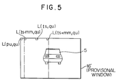
- the total sum Q(s, u) is calculated by scanning the memory 8 while changing the value of s in L (s+i, u+j) from 0 to (k - m) as well as the value u from 0 to (l - n) so as to obtain a scanning position (ps, qu) which minimizes the total sum Q(s, u). Based on the thus obtained scanning position (ps, qu) minimizing the total sum Q(s, u), a provisional window 16 is set.
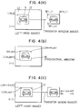
- the provisional window 16 is modified in such a manner that the window 13 is set in a position in which the images inside the window 13 become most symmetrical with respect to the vertical center line of the window 13 so as to always place the image of the object 5 in the form of an automobile in the center of the window 13.
- a total sum of difference T( ⁇ s) for the images in the provisional window 16 is calculated using the following formula:
- scanning a predetermined range for ⁇ s the total sum of difference T( ⁇ s) is successively calculated so as to determine an appropriate position for ⁇ s, which gives a minimum value of T( ⁇ s).
- a new window 13 having a size of m x n is set with its upper left corner being positioned at a location (ps+ ⁇ s, qu).
- Step 1013 the driver sets off or erases the window 13
- the program returns to Step 1003 and no distance calculations and no image following operations are performed until the driver again sets up a new window 13. If, however, the window 13 is not erased or set off by the driver, the program returns to Step 1006 and the above-described operations are repeated. In this manner, the distance to the object 5, which is designated by the driver, can successively be measured using the window 13, while at the same time, the driver can ascertain the manner of image following through the screen of the display 11.
- FIG. 6(a) and 6(b) the construction of the apparatus, and the manner of detecting the distance to a preceding vehicle, defining the image of an object 5 by the driver using a window 13, and setting up a provisional window based on the image of the object 5 defined by the window 13, are substantially the same as in the first-mentioned embodiment, but there is a difference in the manner of setting up a new window on the basis of a provisional window.
- the microprocessor of this embodiment includes, instead of the symmetry evaluating means and the reference image setting means of the previous embodiment, a symmetry axis determining means for determining the axis of symmetry of image signals within the provisional window, and a reference image setting means for setting, as reference image signals, a new window having a prescribed center line positioned at the location of the axis of symmetry of image signals therein.
- this embodiment differs from the previous embodiment of Figs. 3(a) and 3(b) in Step 1012' alone.
- the axis of symmetry in the provisional window is detected based solely on the image signals in the window without scanning it, and then on the basis of the thus detected axis of symmetry, a new window is set.
- a new window is set.
- a total sum of the difference T(ts) between the value (i.e., 0 or 1) of a picture element L(ts-i, qu+j) and that of another picture element L(ts+i, qu+j) is calculated using the following formula: where mm is a value less than m.
- a provisional window can be set using the following formula:
- one pair of right and left optical systems 1, 2 are disposed in a horizontally spaced relation, they may be disposed in a different manner. For example, they can be disposed in a vertically spaced relation or in an obliquely or diagonally spaced relation, while providing substantially the same results.
- one pair of separate image sensors 3, 4 are employed, a single image sensor can be utilized which has an image-sensing area divided into two for the respective optical systems.
- a window is set up in the images displayed on a screen of a display, and the images within the window are successively stored in a memory so that one image within the window at a time, which is similar to the last stored image, is searched for.
- a provisional window containing the thus searched similar image is formed and then shifted little by little so as to find a proper position of the provisional window at which the best symmetry of the image within the window is obtained.
- the most symmetrical window thus found is stored in a memory as a new window.
- the distance detecting apparatus of the invention can identify in a reliable manner a preceding vehicle, which is generally symmetrical with respect to its vertical center line, and successively measure the distance to the target preceding vehicle in a highly accurate manner.
Landscapes
- Physics & Mathematics (AREA)
- Engineering & Computer Science (AREA)
- General Physics & Mathematics (AREA)
- Electromagnetism (AREA)
- Radar, Positioning & Navigation (AREA)
- Remote Sensing (AREA)
- Computer Networks & Wireless Communication (AREA)
- Multimedia (AREA)
- Theoretical Computer Science (AREA)
- Measurement Of Optical Distance (AREA)
- Length Measuring Devices By Optical Means (AREA)
Applications Claiming Priority (2)
| Application Number | Priority Date | Filing Date | Title |
|---|---|---|---|
| JP154406/90 | 1990-06-13 | ||
| JP2154406A JPH0812072B2 (ja) | 1990-06-13 | 1990-06-13 | 距離測定装置 |
Publications (3)
| Publication Number | Publication Date |
|---|---|
| EP0465863A2 true EP0465863A2 (fr) | 1992-01-15 |
| EP0465863A3 EP0465863A3 (en) | 1992-06-10 |
| EP0465863B1 EP0465863B1 (fr) | 1995-12-27 |
Family
ID=15583456
Family Applications (1)
| Application Number | Title | Priority Date | Filing Date |
|---|---|---|---|
| EP91109711A Expired - Lifetime EP0465863B1 (fr) | 1990-06-13 | 1991-06-13 | Appareil et méthode de détermination de distance pour un véhicule |
Country Status (4)
| Country | Link |
|---|---|
| US (1) | US5159557A (fr) |
| EP (1) | EP0465863B1 (fr) |
| JP (1) | JPH0812072B2 (fr) |
| DE (1) | DE69115772T2 (fr) |
Cited By (2)
| Publication number | Priority date | Publication date | Assignee | Title |
|---|---|---|---|---|
| EP0567013A1 (fr) * | 1992-04-20 | 1993-10-27 | Mitsubishi Denki Kabushiki Kaisha | Dispositif de détection de la distance entre véhicules |
| GB2373941A (en) * | 2000-10-17 | 2002-10-02 | Advanced Realtime Tracking Gmb | Stereogrammetry with camera and window tracking |
Families Citing this family (26)
| Publication number | Priority date | Publication date | Assignee | Title |
|---|---|---|---|---|
| JP3110095B2 (ja) * | 1991-09-20 | 2000-11-20 | 富士通株式会社 | 測距方法及び測距装置 |
| JP2800530B2 (ja) * | 1992-02-28 | 1998-09-21 | 三菱電機株式会社 | 車間距離検出装置 |
| JPH0674761A (ja) * | 1992-08-28 | 1994-03-18 | Mitsubishi Electric Corp | 距離測定装置 |
| US5877897A (en) | 1993-02-26 | 1999-03-02 | Donnelly Corporation | Automatic rearview mirror, vehicle lighting control and vehicle interior monitoring system using a photosensor array |
| US6822563B2 (en) | 1997-09-22 | 2004-11-23 | Donnelly Corporation | Vehicle imaging system with accessory control |
| JP2887039B2 (ja) * | 1993-03-26 | 1999-04-26 | 三菱電機株式会社 | 車両周辺監視装置 |
| US5586063A (en) * | 1993-09-01 | 1996-12-17 | Hardin; Larry C. | Optical range and speed detection system |
| US5627510A (en) * | 1994-09-12 | 1997-05-06 | Yuan; Zhiping | Vehicular safety distance alarm system |
| AU690230B2 (en) * | 1995-01-18 | 1998-04-23 | Larry C. Hardin | Optical range and speed detection system |
| US6891563B2 (en) | 1996-05-22 | 2005-05-10 | Donnelly Corporation | Vehicular vision system |
| US5684697A (en) * | 1995-06-26 | 1997-11-04 | Mullen; Charles H. | Driver emulative vehicle control system |
| US5835880A (en) * | 1995-07-19 | 1998-11-10 | Vi & T Group, Inc. | Apparatus and method for vehicle following with dynamic feature recognition |
| US7655894B2 (en) | 1996-03-25 | 2010-02-02 | Donnelly Corporation | Vehicular image sensing system |
| JPH11142520A (ja) * | 1997-11-06 | 1999-05-28 | Omron Corp | 測距装置の軸調整方法及び軸ずれ検出方法並びに測距装置 |
| US6225918B1 (en) | 1999-02-19 | 2001-05-01 | Bing Kam | Automatic warning signal system for vehicles |
| JP4265876B2 (ja) * | 2000-11-06 | 2009-05-20 | 富士フイルム株式会社 | 画像を幾何学的に計測するための計測処理装置 |
| AU2003225228A1 (en) | 2002-05-03 | 2003-11-17 | Donnelly Corporation | Object detection system for vehicle |
| US7526103B2 (en) | 2004-04-15 | 2009-04-28 | Donnelly Corporation | Imaging system for vehicle |
| US7881496B2 (en) | 2004-09-30 | 2011-02-01 | Donnelly Corporation | Vision system for vehicle |
| JP2006151125A (ja) * | 2004-11-26 | 2006-06-15 | Omron Corp | 車載用画像処理装置 |
| US7639841B2 (en) * | 2004-12-20 | 2009-12-29 | Siemens Corporation | System and method for on-road detection of a vehicle using knowledge fusion |
| US8164628B2 (en) * | 2006-01-04 | 2012-04-24 | Mobileye Technologies Ltd. | Estimating distance to an object using a sequence of images recorded by a monocular camera |
| WO2008024639A2 (fr) | 2006-08-11 | 2008-02-28 | Donnelly Corporation | Système de commande automatique de phare de véhicule |
| US20080059069A1 (en) * | 2006-08-30 | 2008-03-06 | Trutna William R | System and method for detecting an object in the path of a vehicle |
| DE102014107305A1 (de) * | 2014-05-23 | 2015-11-26 | Valeo Schalter Und Sensoren Gmbh | Parkassistenzvorrichtung für ein Kraftfahrzeug |
| JP6550881B2 (ja) * | 2014-07-14 | 2019-07-31 | 株式会社リコー | 立体物検出装置、立体物検出方法、立体物検出プログラム、及び移動体機器制御システム |
Family Cites Families (13)
| Publication number | Priority date | Publication date | Assignee | Title |
|---|---|---|---|---|
| JPS6033352B2 (ja) * | 1980-02-19 | 1985-08-02 | 三菱電機株式会社 | 画像目標追尾装置 |
| JPS58196412A (ja) * | 1982-05-12 | 1983-11-15 | Mitsubishi Electric Corp | 距離計測器 |
| JPS61278775A (ja) * | 1985-06-03 | 1986-12-09 | Nissan Motor Co Ltd | 先行車検出装置 |
| US4819169A (en) * | 1986-09-24 | 1989-04-04 | Nissan Motor Company, Limited | System and method for calculating movement direction and position of an unmanned vehicle |
| JPS62182613A (ja) * | 1986-12-24 | 1987-08-11 | Ricoh Co Ltd | 距離検出装置 |
| IT1202534B (it) * | 1987-02-13 | 1989-02-09 | Tecnomare Spa | Apparecchiatura per il rilevamento in continuo della distanza da essa di un punto prefissato,anche mobile |
| JPS63314618A (ja) * | 1987-06-17 | 1988-12-22 | Nissan Motor Co Ltd | 自律走行車両制御装置 |
| JP2570315B2 (ja) * | 1987-09-01 | 1997-01-08 | アイシン精機株式会社 | 車上距離検出装置 |
| US4858132A (en) * | 1987-09-11 | 1989-08-15 | Ndc Technologies, Inc. | Optical navigation system for an automatic guided vehicle, and method |
| US5036474A (en) * | 1989-03-31 | 1991-07-30 | Honeywell Inc. | Motion detection and tracking from a mobile platform |
| US4970653A (en) * | 1989-04-06 | 1990-11-13 | General Motors Corporation | Vision method of detecting lane boundaries and obstacles |
| US4987357A (en) * | 1989-12-18 | 1991-01-22 | General Motors Corporation | Adaptive motor vehicle cruise control |
| JP6033352B2 (ja) | 2015-03-26 | 2016-11-30 | ドーエイ外装有限会社 | 目地装置 |
-
1990
- 1990-06-13 JP JP2154406A patent/JPH0812072B2/ja not_active Expired - Fee Related
-
1991
- 1991-06-11 US US07/713,204 patent/US5159557A/en not_active Expired - Lifetime
- 1991-06-13 DE DE69115772T patent/DE69115772T2/de not_active Expired - Fee Related
- 1991-06-13 EP EP91109711A patent/EP0465863B1/fr not_active Expired - Lifetime
Cited By (3)
| Publication number | Priority date | Publication date | Assignee | Title |
|---|---|---|---|---|
| EP0567013A1 (fr) * | 1992-04-20 | 1993-10-27 | Mitsubishi Denki Kabushiki Kaisha | Dispositif de détection de la distance entre véhicules |
| US5369590A (en) * | 1992-04-20 | 1994-11-29 | Mitsubishi Denki Kabushiki Kaisha | Inter-vehicle distance detecting device |
| GB2373941A (en) * | 2000-10-17 | 2002-10-02 | Advanced Realtime Tracking Gmb | Stereogrammetry with camera and window tracking |
Also Published As
| Publication number | Publication date |
|---|---|
| JPH0450611A (ja) | 1992-02-19 |
| EP0465863B1 (fr) | 1995-12-27 |
| EP0465863A3 (en) | 1992-06-10 |
| DE69115772D1 (de) | 1996-02-08 |
| DE69115772T2 (de) | 1996-06-05 |
| US5159557A (en) | 1992-10-27 |
| JPH0812072B2 (ja) | 1996-02-07 |
Similar Documents
| Publication | Publication Date | Title |
|---|---|---|
| EP0465863B1 (fr) | Appareil et méthode de détermination de distance pour un véhicule | |
| KR930004880B1 (ko) | 추미식 차간거리 측정장치 | |
| US5424952A (en) | Vehicle-surroundings monitoring apparatus | |
| EP0496411B1 (fr) | Appareil pour estimer une distance pour véhicules | |
| EP0500017B1 (fr) | Dispositif pour détecter la glissière de sécurité | |
| EP0473945A2 (fr) | Appareil de détection de la distance entre voitures | |
| JP2509386B2 (ja) | 距離検出装置 | |
| EP0558027B1 (fr) | Dispositif de mesure de la distance entre véhicules | |
| US5257022A (en) | Method and apparatus for following a vehicle | |
| EP0487100A1 (fr) | Dispositif de suivi d'un véhicule | |
| KR940000019B1 (ko) | 거리측정장치 | |
| EP0474067B1 (fr) | Appareil de détection de distance | |
| EP0529619B1 (fr) | Dispositif de mesure de la distance entre véhicules avec poursuite du véhicule roulant en avant | |
| US5255064A (en) | Distance-measuring equipment | |
| EP0495508B1 (fr) | Dispositif de poursuite d'image | |
| JPH09222432A (ja) | 速度違反車両撮像装置 | |
| JP2527825B2 (ja) | 距離測定装置 | |
| JPH02232511A (ja) | 追尾式車間距離測定装置 | |
| JP2827682B2 (ja) | 車間距離検出装置 | |
| JP2730682B2 (ja) | 画像処理装置 | |
| EP0529558B1 (fr) | Dispositif de mesure de la distance entre véhicules | |
| JP2527231B2 (ja) | 距離測定装置 | |
| JPH04313014A (ja) | 車間距離検出装置 | |
| JP2572161B2 (ja) | 車間距離検出装置 | |
| JP2536969B2 (ja) | 車線変更検出機能を有する追尾式車間距離センサ |
Legal Events
| Date | Code | Title | Description |
|---|---|---|---|
| PUAI | Public reference made under article 153(3) epc to a published international application that has entered the european phase |
Free format text: ORIGINAL CODE: 0009012 |
|
| AK | Designated contracting states |
Kind code of ref document: A2 Designated state(s): DE FR GB |
|
| PUAL | Search report despatched |
Free format text: ORIGINAL CODE: 0009013 |
|
| AK | Designated contracting states |
Kind code of ref document: A3 Designated state(s): DE FR GB |
|
| 17P | Request for examination filed |
Effective date: 19920826 |
|
| 17Q | First examination report despatched |
Effective date: 19940818 |
|
| GRAA | (expected) grant |
Free format text: ORIGINAL CODE: 0009210 |
|
| AK | Designated contracting states |
Kind code of ref document: B1 Designated state(s): DE FR GB |
|
| REF | Corresponds to: |
Ref document number: 69115772 Country of ref document: DE Date of ref document: 19960208 |
|
| ET | Fr: translation filed | ||
| PLBE | No opposition filed within time limit |
Free format text: ORIGINAL CODE: 0009261 |
|
| STAA | Information on the status of an ep patent application or granted ep patent |
Free format text: STATUS: NO OPPOSITION FILED WITHIN TIME LIMIT |
|
| 26N | No opposition filed | ||
| REG | Reference to a national code |
Ref country code: GB Ref legal event code: IF02 |
|
| PGFP | Annual fee paid to national office [announced via postgrant information from national office to epo] |
Ref country code: DE Payment date: 20070607 Year of fee payment: 17 |
|
| PGFP | Annual fee paid to national office [announced via postgrant information from national office to epo] |
Ref country code: GB Payment date: 20070613 Year of fee payment: 17 |
|
| PGFP | Annual fee paid to national office [announced via postgrant information from national office to epo] |
Ref country code: FR Payment date: 20070608 Year of fee payment: 17 |
|
| GBPC | Gb: european patent ceased through non-payment of renewal fee |
Effective date: 20080613 |
|
| REG | Reference to a national code |
Ref country code: FR Ref legal event code: ST Effective date: 20090228 |
|
| PG25 | Lapsed in a contracting state [announced via postgrant information from national office to epo] |
Ref country code: DE Free format text: LAPSE BECAUSE OF NON-PAYMENT OF DUE FEES Effective date: 20090101 |
|
| PG25 | Lapsed in a contracting state [announced via postgrant information from national office to epo] |
Ref country code: GB Free format text: LAPSE BECAUSE OF NON-PAYMENT OF DUE FEES Effective date: 20080613 |
|
| PG25 | Lapsed in a contracting state [announced via postgrant information from national office to epo] |
Ref country code: FR Free format text: LAPSE BECAUSE OF NON-PAYMENT OF DUE FEES Effective date: 20080630 |