EP0488184A2 - Vorrichtung zum Entwickeln eines latenten elektrostatischen Bildes und Tonerbehälter für eine solche Vorrichtung - Google Patents
Vorrichtung zum Entwickeln eines latenten elektrostatischen Bildes und Tonerbehälter für eine solche Vorrichtung Download PDFInfo
- Publication number
- EP0488184A2 EP0488184A2 EP91120205A EP91120205A EP0488184A2 EP 0488184 A2 EP0488184 A2 EP 0488184A2 EP 91120205 A EP91120205 A EP 91120205A EP 91120205 A EP91120205 A EP 91120205A EP 0488184 A2 EP0488184 A2 EP 0488184A2
- Authority
- EP
- European Patent Office
- Prior art keywords
- toner
- toner cartridge
- discharge opening
- tape member
- opening
- Prior art date
- Legal status (The legal status is an assumption and is not a legal conclusion. Google has not performed a legal analysis and makes no representation as to the accuracy of the status listed.)
- Withdrawn
Links
- 238000007789 sealing Methods 0.000 claims abstract description 50
- 230000002093 peripheral effect Effects 0.000 claims description 6
- 238000001514 detection method Methods 0.000 description 11
- 230000000994 depressogenic effect Effects 0.000 description 4
- 230000005540 biological transmission Effects 0.000 description 3
- 238000010276 construction Methods 0.000 description 2
- 239000007779 soft material Substances 0.000 description 2
- 230000001174 ascending effect Effects 0.000 description 1
- 238000010586 diagram Methods 0.000 description 1
- 238000010438 heat treatment Methods 0.000 description 1
- 230000033001 locomotion Effects 0.000 description 1
- 239000004033 plastic Substances 0.000 description 1
- 239000002985 plastic film Substances 0.000 description 1
- 229920006255 plastic film Polymers 0.000 description 1
- 239000011347 resin Substances 0.000 description 1
- 229920005989 resin Polymers 0.000 description 1
Images






Classifications
-
- G—PHYSICS
- G03—PHOTOGRAPHY; CINEMATOGRAPHY; ANALOGOUS TECHNIQUES USING WAVES OTHER THAN OPTICAL WAVES; ELECTROGRAPHY; HOLOGRAPHY
- G03G—ELECTROGRAPHY; ELECTROPHOTOGRAPHY; MAGNETOGRAPHY
- G03G15/00—Apparatus for electrographic processes using a charge pattern
- G03G15/06—Apparatus for electrographic processes using a charge pattern for developing
- G03G15/08—Apparatus for electrographic processes using a charge pattern for developing using a solid developer, e.g. powder developer
-
- G—PHYSICS
- G03—PHOTOGRAPHY; CINEMATOGRAPHY; ANALOGOUS TECHNIQUES USING WAVES OTHER THAN OPTICAL WAVES; ELECTROGRAPHY; HOLOGRAPHY
- G03G—ELECTROGRAPHY; ELECTROPHOTOGRAPHY; MAGNETOGRAPHY
- G03G15/00—Apparatus for electrographic processes using a charge pattern
- G03G15/06—Apparatus for electrographic processes using a charge pattern for developing
- G03G15/08—Apparatus for electrographic processes using a charge pattern for developing using a solid developer, e.g. powder developer
- G03G15/0822—Arrangements for preparing, mixing, supplying or dispensing developer
- G03G15/0877—Arrangements for metering and dispensing developer from a developer cartridge into the development unit
- G03G15/0881—Sealing of developer cartridges
- G03G15/0882—Sealing of developer cartridges by a peelable sealing film
-
- G—PHYSICS
- G03—PHOTOGRAPHY; CINEMATOGRAPHY; ANALOGOUS TECHNIQUES USING WAVES OTHER THAN OPTICAL WAVES; ELECTROGRAPHY; HOLOGRAPHY
- G03G—ELECTROGRAPHY; ELECTROPHOTOGRAPHY; MAGNETOGRAPHY
- G03G15/00—Apparatus for electrographic processes using a charge pattern
- G03G15/06—Apparatus for electrographic processes using a charge pattern for developing
- G03G15/08—Apparatus for electrographic processes using a charge pattern for developing using a solid developer, e.g. powder developer
- G03G15/0822—Arrangements for preparing, mixing, supplying or dispensing developer
- G03G15/0865—Arrangements for supplying new developer
- G03G15/0875—Arrangements for supplying new developer cartridges having a box like shape
-
- Y—GENERAL TAGGING OF NEW TECHNOLOGICAL DEVELOPMENTS; GENERAL TAGGING OF CROSS-SECTIONAL TECHNOLOGIES SPANNING OVER SEVERAL SECTIONS OF THE IPC; TECHNICAL SUBJECTS COVERED BY FORMER USPC CROSS-REFERENCE ART COLLECTIONS [XRACs] AND DIGESTS
- Y10—TECHNICAL SUBJECTS COVERED BY FORMER USPC
- Y10S—TECHNICAL SUBJECTS COVERED BY FORMER USPC CROSS-REFERENCE ART COLLECTIONS [XRACs] AND DIGESTS
- Y10S222/00—Dispensing
- Y10S222/01—Xerography
Definitions
- the present invention relates to an electrostatic latent image-developing device utilized for an image-forming machine such as an electrostatic copying machine or a laser printer. More specifically, the invention relates to an electrostatic latent image-developing device of a type which is replenished with toner by renewing a toner cartridge and to the toner cartridge used for such an electrostatic latent image-developing device.
- toner is imparted to an electrostatic latent image that is to be developed in order to develop it into a toner image. Therefore, the toner is consumed as the developing is continued, and the electrostatic latent image-developing device must be replenished with the toner after the developing has been executed many times.
- a toner replenishing system is conveniently employed according to which a toner cartridge is renewed to replenish the toner.
- the electrostatic latent image-developing device that employs the above toner replenishing system has a toner cartridge-holding means in which the toner cartridge is detachably held.
- the toner cartridge-holding means has an opening for receiving the toner.
- the toner cartridge includes a container having a toner discharge opening, toner contained in the container, and a sealing means for sealing the toner discharge opening.
- the toner discharge opening is formed in the lower wall of the container, and the sealing means is constituted by a tape member which is peelably stuck to the lower wall of the container.
- the toner in the container is discharged into the toner-receiving opening through the toner discharge opening, so that the electrostatic latent image-developing device is replenished with the toner.
- the tape member is peeled off from the container usually by gripping its end and pulling it off.
- Japanese Laid-Open Utility Model Publication No. 224364/1983 discloses a toner cartridge in which a slide member is fitted to the container in relation to the toner discharge opening of the container, and the tape member stuck to the container is linked to the slide member.
- the slide member is moved in a predetermined direction relative to the container, whereby the tape member is peeled off from the container and the toner discharge opening is opened.
- the slide member is returned back to the initial position to cover the toner discharge opening with the tape member.
- the conventional electrostatic latent image-developing device that is replenished with the toner by renewing the toner cartridge has the following problems that must be solved; i.e.,
- a first object of the present invention is to provide an improved electrostatic latent image-developing device that is capable of opening the toner discharge opening without requiring cumbersome operation and without causing the toner to be scattered, and to provide a toner cartridge that can be used for the above electrostatic latent image-developing device.
- a second object of the present invention is to provide an improved electrostatic latent image-developing device which is capable of very easily and reliably closing the toner discharge opening to fully reliably prevent the toner remaining in the container from scattering around at the time of taking the toner cartridge out of the toner cartridge-holding means, and to provide a toner cartridge used for the above electrostatic latent image-developing device.
- a third object of the present invention is to provide an improved electrostatic latent image-developing device which makes it easy to take out the toner cartridge from the toner cartridge-holding means and to fit the toner cartridge to the toner cartridge-holding means.
- a fourth object of the present invention is to provide an improved electrostatic latent image-developing device which is capable of very easily opening the toner discharge opening of the toner cartridge and very easily closing the opened toner discharge opening without making the toner cartridge-holding means to be excessively bulky and without permitting the toner to scatter around.
- the sealing means is constituted by a tape member that moves across the toner discharge opening of the container, a toner passage opening is formed in the tape member, and the toner passage opening is positioned at the toner discharge opening by moving the tape member, so that the toner is discharge from the container through the toner discharge opening and the toner passage opening.
- the toner cartridge is provided with a take-up means, and the front end of the tape member is connected to the take-up means.
- the take-up means is provided with an input means
- the toner cartridge-holding means is provided with an output means that is connected to a drive source, and the output means and the input means are drivably coupled together when the toner cartridge is fitted to the predetermined position of the toner cartridge-holding means, so that the take-up means is driven by the drive source to move the tape member.
- the toner cartridge is provided with a delivering means and a guide means disposed on the side of one edge of the toner discharge opening, and the take-up means is disposed on the side of other edge of the toner discharge opening.
- a preferred example of tape member constituting the sealing means includes a sealing portion that extends across the toner discharge opening of the container under the initial condition and is peelably stuck to the container over a region surrounding the toner discharge opening, a passage opening portion which is positioned behind the sealing portion and in which the toner passage opening is formed, a front portion that is folded back at the front edge of the sealing portion, passes along the outer side thereof, turns around the guide means, and further extends to the take-up means, and a tentative sealing portion position behind the passage opening. It is preferred that the rear end of the toner passage opening formed in the tape member becomes gradually narrow toward the rear side.
- a hoist means is disposed in the toner cartridge-holding means to move the toner cartridge up and down between the predetermined fitting position and an elevated position raised from the fitting position.
- a preferred example of the hoist means includes a hoist frame that is mounted to move up and down, and the toner cartridge is fitted to the hoist frame. It is desired that the toner cartridge-holding means has a bottom wall in which an opening is formed to receive the toner, a buffer member is disposed on the bottom wall, the toner discharge opening is formed in the lower wall of the container of the toner cartridge, and the lower wall of the container is pressed onto the buffer member when the toner cartridge is lowered to the fitting position by the action of the hoist means.
- an opening closed by a covering member is arranged over the toner cartridge-holding means so as to be freely opened and closed, and the toner cartridge partly protrudes upwardly beyond the above port when the covering member is opened and the toner cartridge is raised to the elevated position.
- the toner passage opening formed in the tape member is positioned at the toner discharge opening by moving the tape member that constitutes the sealing member, so that the toner discharge opening is opened and the toner is discharged from the container passing through the toner discharge opening and the toner passage opening.
- the tape member is moved by the take-up means disposed in the toner cartridge, and the take-up means is driven by the drive source disposed in the toner cartridge-holding means via output means disposed in the toner cartridge-holding means and input means disposed in the toner cartridge.
- the sealing portion is positioned at the toner discharge opening.
- the sealing portion is, of which the inner surface is adhered with toner, taken up by the take-up means without being outwardly exposed.
- the tape member is delivered from the delivering means so that the false-sealing portion is positioned at the toner discharge opening thereby to close the toner discharge opening.
- the toner cartridge is taken out from the toner cartridge-holding means after the toner cartridge has been raised to the elevated position from the fitting position. Moreover, once the toner cartridge is fitted to the elevated position by hand, the toner cartridge can be lowered to the predetermined fitting position without requiring any additional manual operation. Thus, the toner cartridge can be taken out or fitted very easily when it is outwardly protruded only partly at the elevated position.
- an electrostatic latent image-developing device generally designated at 2 is constituted by a developing unit 4, a toner carrier unit 6 and a toner feeding unit 8.
- the developing unit 4 includes a suitable developing mechanism 10 such as a magnetic brush developing mechanism.
- the developing mechanism applies a developer, which may be a so-called two-component developer consisting of a toner and a carrier, onto a rotary drum 12, in order to develop an electrostatic latent image formed on the rotary drum 12 into a toner image.
- the toner is carried from the toner carrier unit 6 to the developing unit 4.
- the toner feeding unit 8 is equipped with a toner cartridge-holding means 14 and a toner cartridge 16 detachably fitted into the toner cartridge-holding means 14.
- toner T is contained in the toner cartridge 16 and is discharged to the toner carrier unit 6 to the developing unit 4.
- the electrostatic latent image-developing device 2 and the rotary drum 12 are disposed in a housing 18 (Fig. 1 shows part of it only) of an image-forming machine such as an electrostatic copying machine or a laser printer.
- the upper wall of the housing 18 is disposed over the electrostatic latent image-developing device 2, and a port 20 is formed in the upper wall of the housing 18 at a position above the toner feeding unit 8.
- the developing unit 4 and the toner carrier unit 6 of the electrostatic latent image-developing device 2 that is illustrated in Fig. 1 do not constitute novel features in the electrostatic latent image-developing device that is improved according to the present invention but may be known constructions. Hence, their detailed constructions are not described in this specification.
- the toner cartridge-holding means 14 of the toner feeding unit 8 includes a stationary support frame 24.
- This support frame 24 has a bottom wall 26 that extends substantially horizontally, an upright rear wall 28 that upwardly extends from the rear edge of the bottom wall 26, and upright side walls 30 and 32 that upwardly extend from edges on both sides of the bottom wall 26.
- Two openings 34a and 34b for receiving the toner are formed in parallel in the direction of width (perpendicularly to the surface of the paper in Fig. 1) in the central region of the bottom wall 26.
- the openings 34a and 34b for receiving the toner are of a rectangular shape.
- a buffer member 36 is attached to the upper surface of the bottom wall 26 to extend along the periphery of the toner-receiving openings 34a and 34b.
- the buffer member 36 is made of a soft material such as a foamed resin.
- Positioning pins 38 (Fig. 2 shows only one of them) are upwardly protruded at both side portions of the bottom wall 26.
- the upper portion of the positioning pin 38 has a conical shape.
- a short shaft 40 that horizontally protrudes is secured to the front portion of the side wall 30, and a gear 42 is rotatably fitted to the short shaft 40.
- the gear 42 is connected to a drive source M1 which may be an electric motor, via a transmission means (not shown) that includes a gear train.
- a rectangular notch 44 is formed in one side portion at the front edge of the bottom wall 26, and the gear 42 is allowed to protrude upwardly through the notch 44.
- the gear 42 constitutes an output means that is drivably coupled to an input means constituted by gears that are disposed in the toner cartridge 16.
- a rectangular opening 46 is formed adjacent to the notch 44 in the bottom wall 26, and a detection arm of a microswitch 48 attached to the lower surface of the bottom wall 26 protrudes upwardly through the opening 46 (the action of the microswitch 48 will be described later).
- a rectangular opening 50 is formed in one side portion at the rear edge of the bottom wall 26, and a gear 54 rotatably fitted to a short shaft 52 that is secured to the side wall 32 and extends horizontally protrudes upwardly through the opening 50.
- the gear 54 is connected to a drive source M2 which may be an electric motor, via a transmission means (not shown) that includes a gear train.
- a gear in a hoist means that will be described later.
- the toner cartridge-holding means 14 has a hoist means 56 which includes a hoist frame 58.
- the hoist frame 58 is of nearly a rectangular parallelopiped shape having openings in the upper surface and in the lower surface, and further has front and rear walls 60 and 62 as well as side walls 64 and 66.
- a flange 68 that horizontally protrudes outwardly and then upwardly is formed at the upper ends of the front and rear walls 60, 62 and the side walls 64, 66.
- Relatively large notches 70 and 72 are formed in the lower portions of the side walls 64 and 66.
- Each of the notches 70 and 72 has vertical edges 73 and 74 that extend substantially vertically upwards from the lower ends of the side walls 64 and 66 at a predetermined distance in the back-and-forth direction, horizontal edges 75 and 76 that inwardly extend substantially horizontally from the vertical edges 73 and 74, and an arcuate edge 77 that extends arcuately between the horizontal edges 75 and 76.
- Relatively small rectangular notches 78 and 80 are formed at the lower ends on both sides of the front wall 60.
- protrusions 82 that protrudes inwardly (Fig. 3 shows only one of them) are formed at the lower ends on both sides of the front wall 60.
- Protrusions 84 that protrudes inwardly (Fig.
- Short shafts 86 and 88 are formed at the rear portion of each of the side walls 64 and 66 at a distance in the up-and-down direction, and rollers 90 and 92 are rotatably fitted to the short shafts 86 and 88 (Fig. 3 shows only the short shafts 86, 88 and the rollers 90, 92 that are mounted on the side wall 64).
- guide members 94 and 96 are secured, extending vertically, onto the inner surface of both sides of the rear wall 28 of the support frame 24, the guide members 94 and 96 having restriction portions 98 and 100 that extend substantially vertically.
- Short shafts 102 and 104 are secured to the side walls 30 and 32 of the support frame 24 and inwardly protrude substantially horizontally.
- Rotary members 106 and 108 are rotatably fitted to the short shafts 102 and 104.
- the rotary members 106 and 108 have toothed portions 110 and 112 having teeth formed along the peripheries thereof. Hoist pins 114 and 116 that protrude inwardly and substantially horizontally are studded on the inner surface of the toothed portions 110 and 112. As clearly shown in Fig.
- the toothed portion 112 of the rotary member 108 is engaged with the gear 54 that is located in the opening 50 formed in the bottom wall 26, and is drivably coupled to the drive source M2 via this gear 54.
- Short shafts 118 and 120 are further secured to the side walls 30 and 32 of the support frame 24, and gears 122 and 124 are rotatably fitted to the short shafts 118 and 120.
- the gears 122 and 124 are brought into engagement with the toothed portions 110 and 112 of the rotary members 106 and 108, respectively.
- a rotary shaft 130 is rotatably mounted across the protruded portions 126 and 128 that are formed at the front edges of the side walls 30 and 32.
- Gears 132 and 134 are fastened to both ends of the rotary shaft 130, and are brought into engagement with the gears 112 and 124, respectively. Therefore, the rotational driving force transmitted to the rotary member 108 via the gear 54 is further transmitted to the rotary member 106 via toothed portion 112, gear 124, gear 134, rotary shaft 130, gear 132, gear 122 and toothed portion 110, whereby the rotary members 106 and 108 are rotated in the same direction in synchronism with each other.
- the hoist pins 114 and 116 of the rotary members 106 and 108 are maintained at substantially the same angular positions at all times.
- a cam portion 136 is formed integrally with the rotary member 108 on the back surface side of the toothed portion 112.
- the peripheral surface of the cam portion 136 is of a circular shape except a recessed portion 138 that is to be detected.
- Two microswitches 140 and 142 are mounted on the inner surface of side wall 32 of the support frame 24, in relation to the cam portion 136.
- the switches 140 and 142 detect the recessed portion 138 to be detected of the cam portion 136 (the switches 140 and 142 are opened when their detection arms are positioned in the recessed portion 138 to be detected), thereby to detect the rotational angular position of the rotary member 108 (and the rotary member 106).
- the above-mentioned hoist frame 58 has rollers 90 and 92 attached to the outer surfaces of the side walls 64 and 66.
- the rollers 90 and 92 are positioned behind the restriction portions 98 and 100 of guide members 94 and 96 arranged at the rear edges on both sides of the support frame 24, whereby the hoist frame 58 is fitted to the support frame 24, being allowed to ascend and descend freely.
- the hoist pins 114 and 116 of the rotary members 106 and 108 disposed in the support frame 24 protrude inwardly through notches 70 and 72 formed in the side walls 64 and 66 of the hoist frame 58.
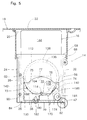
- the hoist frame 58 moves up and down between the lowered position shown in Figs. 1 and 5 and the elevated position shown in Fig. 6.
- the hoist pins 114 and 116 of the rotary members 106 and 108 are positioned at the centers of notches 70 and 72 formed in the side walls 64 and 66 of the hoist frame 58, and do not act on the hoist frame 58.
- the hoist frame 58 has lowered due to its own weight, and the lower surface of the flange 68 formed at the upper end thereof is brought into contact with the upper edges of the rear wall 28 and side walls 30 and 32 of the support frame 24.
- the detection arm of the switch 140 detects the recessed portion 138 formed in the cam portion 136 of the rotary member 108, and is opened.
- the detection arm of the switch 142 is closed by the peripheral surface of cam portion 136 of the rotary member 108.
- the hoist pins 114 and 116 of the rotary members 106 and 108 are acting on the horizontal edges 75 of notches 70 and 72 formed in the side walls 64 and 66 of the hoist frame 58, whereby the hoist frame 58 is raised to a position shown in the drawing.
- the detection arm of the switch 142 detects the recessed portion 138 formed in the cam portion 136 of the rotary member 108 and is opened, whereas the detection arm of the switch 140 is closed by the peripheral surface of the cam portion 136 of the rotary member 108.
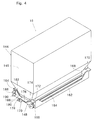
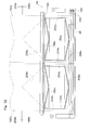
- the toner cartridge 16 will now be described with reference to Figs. 4 and 7 as well as Fig. 1.
- the illustrated toner cartridge 16 is equipped with a plastic container 144 which as a whole is made of a single unit or by joining two or more components together.
- the container 144 has a box-like main portion 146 which contains the toner T.
- the upper half of the main portion 146 is of a rectangular parallelopiped shape, and the lower half thereof has a truncated pyramidal portion and in succession, a relatively small rectangular parallelopiped portion.
- the four side walls downwardly extend with inward inclination and then downwardly extend substantially vertically.
- two toner discharge openings 150a and 150b are formed side by side in the direction of width (in a direction perpendicularly to the surface of the paper in Fig. 7 or in the right-and-left direction in Fig. 8) in the lower wall 148 of the main portion 146.
- the toner discharge openings 150a and 150b may have a rectangular shape.
- the lower wall 148 has a front extended portion 152 and a rear extended portion 154 that extend forwardly and rearwardly.
- melt-adhesion protrusions 156a and 156b are formed in the lower wall 148 to surround the toner discharge ports 150a and 150b.
- Both side portions of the melt-adhesion protrusions 156a and 156b extend straightly, but the front portions and the rear portions are tilted forward from both sides toward the center in the direction of width to protrude in a triangular shape.
- Elongated slits 158 and 160 extending in the direction of width are formed in the front extended portion 152 and in the rear extended portion 154 of the lower wall 148 each in a number of two in parallel in the direction of width.
- the lower wall 148 having front extended portion 152 and rear extended portion 154 further has upright walls that upwardly extend substantially vertically from the four peripheral edges thereof, i.e., has front and rear upright walls 162 and 164, as well as upright walls 166 and 160 on both sides.
- protruded walls 170 that protrude outwardly in the direction of width are formed on the outer surfaces of side walls 166 and 168.
- Each of the protruded walls 170 has an upper horizontal portion 172 that extends substantially horizontally, a tilted portion 174 that extends rearwardly being tilted downwards, an intermediate horizontal portion 176 that rearwardly extends substantially horizontally, a vertical portion 178 that downwardly extends substantially vertically, and a lower horizontal portion 180 that extends substantially horizontally.
- a positioning hole 182 is formed in the lower horizontal portion 180.
- a roller 184 that constitutes a take-up means is rotatably mounted between the front portions of the side walls 166 and 168. One end of the roller 184 that extends in the direction of width along the toner discharge openings 150a and 150b protrudes outwardly through the side wall 166, and a gear 186 is secured to this end.
- the gear 186 constitutes an input means which is drivably coupled to the gear 42 arranged in the aforementioned toner cartridge-holding means 14.
- Rollers 188 and 190 are rotatably mounted between the rear portions of the side walls 166 and 168.
- the rollers 188 and 190 extend in the direction of width along the toner discharge ports 150a and 150b at a distance relative to each other in the up-and-down direction.
- the roller 188 constitutes a delivering means and the roller 190 constitutes a guide means.
- roller 190 that constitutes the guide means can be rotated with a very small torque, but the roller 188 that constitutes the delivering means is provided with a suitable brake means and is rotated with a torque which is greater than a predetermined value.
- the brake means will be constituted by a soft material (not shown) that is brought in contact with the roller 188.
- the toner cartridge 16 is further equipped with tape members 192a and 192b arranged in relation to the toner discharge ports 150a and 150b. It is desired that the tape members 192a and 192b that constitute a sealing means are made of a suitable plastic film.
- the tape members 192a and 192b are connected at their rear edges by adhesion or any other means to the roller 188 that constitutes the delivering means and are wound on the roller 188 over a required length.
- the tape members 192a and 192b extend from the roller 188 through slits 160 formed in the rear extended portion 154 of the lower wall 148, and further extend along the outside of the lower wall 148 to cover the toner discharge openings 150a and 150b.
- the peelable sticking is conveniently realized by heating the sealing portions 194a and 194b of the tape members 192a and 192b and melt-adhering them to the melt-adhesion protrusions 156a and 156b formed on the outer surface of the lower wall 148.
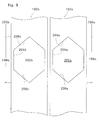
- the tape members 192a and 192b further have front portions 196a and 196b that are folded back at the front side (right side in Fig.
- passage opening portions 198a and 198b as well as tentative-sealing portions 200a and 200b are included in the portions at the rear of the sealing portions 194a and 194b of the tape members 192a and 192b.
- Toner passage openings 202a and 202b are formed in the passage opening portions 198a and 198b.
- the toner passage openings 202a and 202b include front side extended portions 206a, 206b and rear side extended portions 208a, 208b as well as rectangular central portions 204a and 204b which are substantially the same as or slightly greater than the toner discharge openings 150a and 150b.
- the rear side extended portions 208a and 208b of the toner passage ports 202a and 202b are gradually narrow rearwardly (the reason will be described later).
- the rear side extended portions 208a and 208b has an isosceles triangular shape that become gradually narrow rearwardly
- the front side extended portions 206a and 206b has an isosceles triangular shape that become gradually narrow toward the front.
- the toner cartridge 16 can be fitted to the toner cartridge-holding means 14 in the following manner.
- the cover member 22 at the closed position shown in Figs. 1 and 5 is turned by hand to the open position shown in Fig. 6 in order to open the opening 20 that is formed in the upper wall of the housing 18.
- a toner cartridge loading switch that is arranged on an operation panel (not shown) disposed on the front surface of the housing 18 is depressed in order to energize the drive source M2 (Fig. 2) to which the rotary members 106 and 108 are drivably coupled and to turn the rotary members 106 and 108 in the clockwise direction in Figs. 5 and 6 from the angular position shown in Fig.
- the hoist pins 114 and 116 studded on the rotary members 106 and 108 come in contact with the horizontal edges 75 of the notches 70 and 72 formed in the side walls 64 and 66 of the hoist frame 58 to raise the hoist frame 58 from the lowered position shown in Fig. 5 to the elevated position shown in Fig. 6.
- the toner cartridge 16 is fitted into the hoist frame 58 that is located at the elevated position, through the opening 20 that is open.
- the four corner portions on the bottom wall 148 of the toner cartridge 16 comes in contact with the protrusions 82 and 84 formed at the lower four corner portions of the hoist frame 58.
- the toner cartridge 16 is held in the hoist frame 58.
- the upper portion of the toner cartridge 16 protrudes upwardly through the port 20 that is open. Therefore, the toner cartridge 16 can be fitted very easily to the hoist frame 58.
- the toner cartridge loading switch (not shown) is depressed again to energize the drive source M2 (Fig. 2) to which the rotary members 106 and 108 are drivably coupled in order to turn the rotary members 106 and 108 in the clockwise direction in Figs. 5 and 6 from the angular position shown in Fig. 6.
- the recessed portion 138 to be detected of the cam portion 136 formed integrally with the rotary member 108 is detected by the microswitch 140, whereby the drive source M2 is de-energized and the rotary members 106 and 108 cease to rotate.
- the drive source M2 is de-energized and the rotary members 106 and 108 cease to rotate.
- the hoist frame 58 descends, the toner cartridge 16 fitted thereto descends, too.
- the toner cartridge 16 is limited from descending as the lower wall 148 of the container 144 of the toner cartridge 16 comes in contact with the buffer member 36 arranged on the bottom wall 26 of the stationary support frame 24.
- the hoist frame 58 descends to the lowered position shown in Fig. 5, the four corner portions of the lower wall 148 of the container 144 is positioned slightly above the protrusions 82 and 84 provided at the lower four corner portions of the hoist frame 58.
- the hoist pins 114 and 116 separated away from the edges of notches 70 and 72 formed in the side walls 64 and 66 of the hoist frame 58 move along the tilted portion 174 and intermediate horizontal portion 180 of the protruded wall 170 formed on the outer surface of upright side walls 166 and 168 of the container 144, and act on the upper surface of the intermediate horizontal portion 180 to downwardly urge the toner cartridge 16 so that the lower wall 148 of the container 144 is pressed onto the buffer member 36 arranged on the bottom wall 26 of the support frame 24.
- the toner cartridge 16 is resiliently held fully reliably at the fitting position shown in Fig. 5.
- the toner cartridge 16 is lowered to the fitting position shown in Fig.
- the positioning pin 38 disposed on the bottom wall 26 of the support frame 24 penetrates through the positioning hole 182 formed in the lower horizontal portion 180 of the protruded wall 170 of the container 144, whereby the toner cartridge 16 is positioned at a required position very precisely, enabling the toner discharge ports 150a and 150b formed in the lower wall 148 of the container 144 to be in very precise match with the toner-receiving openings 34a and 34b formed in the bottom wall 26 of the support frame 24.
- the gear 186 (input means) of the toner cartridge 16 is drivably coupled to the gear 42 (output means) of the toner cartridge-holding means 14 and consequently, the roller 184 of the toner cartridge 16 is drivably coupled to the drive source M1.
- a portion where the tape member 192a of the toner cartridge 16 passes through the slit 158 formed in the front extended portion 152 of the lower wall 148 acts on the detection arm of the switch 48 disposed in the toner cartridge-holding means 14 to close the switch 48.
- the operator moves the covering member 22 from the open position shown in Fig. 6 to the closed position shown in Figs. 1 and 5 and further depresses a toner replenishment switch (not shown) on the operation panel (not shown) disposed on the front surface of the housing 18. Then, the drive source M1 is energized, the roller 184 which constitutes the take-up means in the toner cartridge 16 is rotated in the counterclockwise direction in Fig. 7, and the tape members 192a and 192b whose front edges are connected to the roller 184 are taken up by the roller 184. As shown in Fig.
- the sealing portions 194a and 194b of the tape members 192a and 192b are pulled leftwardly in Figs. 7 and 10 and are peeled off from the lower wall 148 of the container 144.
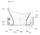
- the tape members 192a and 192b that are delivered from the roller 188 constituting the delivering means pass on the roller 190 that constitutes the guide means, and then pass on the outside of the lower wall 148 of the container 144, as shown in Fig. 11.
- the roller 184 is rotated until the tape members 192a and 192b are placed under a condition shown in Figs.
- the detection arm of the switch 48 disposed in the toner cartridge-holding means 14 protrudes through the toner passage opening 202a formed in the tape member 192a, and the switch 48 is opened.
- the drive source M1 is de-energized, whereby the roller 184 ceases to rotate and the tape members 192a and 192b are no more taken up.
- the central portions 204a and 204b of the toner passage openings 202a and 202b formed in the tape members 192a and 192b are brought in match with the toner discharge openings 150a and 150b formed in the lower wall 148 of the container 144 and, thus, the toner discharge openings 150a and 150b are opened (in Fig.
- the passage opening portions 198a and 198b of the tape members 192a and 192b in which the toner passage openings 202a and 202b are formed are indicated by a two-dot chain line for the purpose of convenience).
- the toner discharge openings 150a and 150b are opened, the toner T contained in the container 144 is discharged downwards through the toner discharge openings 150a and 150b and toner passage openings 202a and 202b, and is fed into the toner carrier unit 6 through the toner-receiving openings 34a and 34b formed in the bottom wall 26 of the toner cartridge-holding means 14.
- the toner replenishment switch (not shown) is depressed. Then, the drive source M1 (Fig. 2) is energized, the roller 184 constituting the take-up means in the toner cartridge 16 is rotated in the counterclockwise direction in Figs. 11 and 13, and the tape members 192a and 192b are taken up by the roller 184.
- the passage opening portions 198a and 198b of the tape members 192a and 192b are taken up by the roller 184, and the tentative sealing portions 200a and 200b of the tape members 192a and 192b cover the toner discharge openings 150a and 150b formed in the lower wall 148 of the container 144.
- the toner passage openings 202a and 202b formed in the tape members 192a and 192b have rear extended portions 208a and 208b of an isosceles triangular shape that become gradually narrow rearwardly.
- the tape members 192a and 192b can be taken up fully smoothly without encountering such a problem that the rear edges of the toner passage openings 202a and 202b are caught by the front edges of the toner discharge openings 150a and 150b.
- the straight rear edges at the central portions 204a and 204b of the toner passage openings 202a and 202b may be displaced into the toner discharge openings 150a and 150b and caught by the front edges of the toner discharge openings 150a and 150b.
- the cover member 22 disposed on the upper wall of the housing 18 is turned to the open position shown in Fig. 6 to open the opening 20 formed in the upper wall of the housing 18.
- the toner cartridge loading switch (not shown) is depressed.
- the hoist frame 58 is raised to the elevated position shown in Fig. 6 in a manner as described above, and the toner cartridge 16 is raised to the elevated position shown in Fig. 6, too.
- the depleted toner cartridge 16 in which the toner T was consumed is removed from the hoist frame 58 and a new toner cartridge 16 is fitted to the hoist frame 58.
- the hoist frame 58 is raised to the elevated position shown in Fig.
- the upper half portion of the depleted toner cartridge 16 protrudes upwardly beyond the opening 20 formed in the upper wall of the housing 18. It is therefore allowed to very easily remove the depleted toner cartridge 16 from the hoist frame 58.
- the toner discharge openings 150a and 150b formed in the lower wall 148 of the container 144 have been closed by the false-sealing portions 200a and 200b of the tape members 192a and 192b. Therefore, the toner T that may remain in small amounts in the container 144 is prevented from scattering around.
- the hoist frame 58 is lowered in a manner as described above. The new toner cartridge 16 is then fitted as required to the toner cartridge-holding means 14, and the toner discharge openings 150a and 150b of the container 144 are opened to feed the toner again to the toner carrier unit 6.
- the hoist frame 58 is disposed in the toner cartridge-holding means 14, and the toner cartridge 16 is raised and lowered while being held in the hoist frame 58.
- it is also allowable to directly raise and lower the toner cartridge 16 without employing the hoist frame 58.
- the input means (gear 186) of the toner cartridge 16 is drivably coupled to the output means (gear 42) of the toner cartridge-holding means 14 when the toner cartridge 16 is fitted as required, and the tape members 192a and 192b in the toner cartridge 16 are taken up by the roller 184 which is driven by the drive source M1 such as an electric motor provided in the toner cartridge-holding means 14. It is, however, also allowable to constitute the device in a manner as described below instead of the above-mentioned constitution.
- a rack extending in the up-and-down direction is disposed in the stationary support frame 24 in the toner cartridge-holding means 14, so that the gear 186 of the toner cartridge 16 is rotated by the action of the rack at the time when the toner cartridge 16 is manually or automatically raised or lowered, causing the roller 184 to be rotated to take up the tape members 192a and 192b.
- the covering member 122 disposed on the upper surface of the housing 18 is provided with a gear, and the rotation of this gear produced by the opening or closure of the covering member 122 is transmitted to the gear 186 of the toner cartridge 16 fitted in the toner cartridge-holding means 14 via a suitable transmission means, in order to rotate the roller 184 and to take up the tape members 192a and 192b.
- the tape members 192a and 192b are wrapped round the rollers 184, 188 and 190 of the container 144 in a predetermined manner, the tape members 192a and 192b having sealing portions 194a, 194b and passage openings 198a, 198b, as well as front portions 196a, 196b and tentative sealing portions 200a, 200b. It is, however, also allowable to wrap up the tape members 192a and 192b without using the roller 190, or to wrap up the tape members 192a and 192b by employing one or two or more additional rollers.
- the toner discharge openings 150a and 150b are closed by the tentative sealing portions 200a and 200b of the tape members 192a and 192b after the toner T in the container 144 is consumed. It is, however, further allowable to close the toner discharge openings 150a and 150b by moving the tape members 192a and 192b in the opposite direction so that the sealing portions 194a and 194b are positioned at the toner discharge openings 150a and 150b after the toner T in the container 144 is consumed.
Landscapes
- Physics & Mathematics (AREA)
- General Physics & Mathematics (AREA)
- Dry Development In Electrophotography (AREA)
Applications Claiming Priority (2)
| Application Number | Priority Date | Filing Date | Title |
|---|---|---|---|
| JP32345490 | 1990-11-26 | ||
| JP323454/90 | 1990-11-26 |
Publications (2)
| Publication Number | Publication Date |
|---|---|
| EP0488184A2 true EP0488184A2 (de) | 1992-06-03 |
| EP0488184A3 EP0488184A3 (en) | 1993-05-12 |
Family
ID=18154855
Family Applications (1)
| Application Number | Title | Priority Date | Filing Date |
|---|---|---|---|
| EP19910120205 Withdrawn EP0488184A3 (en) | 1990-11-26 | 1991-11-26 | Electrostatic latent image-developing device and toner cartridge used therefor |
Country Status (5)
| Country | Link |
|---|---|
| US (1) | US5142335A (de) |
| EP (1) | EP0488184A3 (de) |
| JP (1) | JP3062604B2 (de) |
| KR (1) | KR920010367A (de) |
| CA (1) | CA2055873A1 (de) |
Cited By (6)
| Publication number | Priority date | Publication date | Assignee | Title |
|---|---|---|---|---|
| EP0514874A3 (en) * | 1991-05-20 | 1993-05-12 | Mita Industrial Co., Ltd. | Toner feeding device |
| EP0607528A3 (de) * | 1992-12-03 | 1994-08-10 | Eastman Kodak Company | Tonerbehälter und dafür vorgesehene Aufnahmevorrichtung |
| EP0736818A1 (de) * | 1995-04-03 | 1996-10-09 | Canon Kabushiki Kaisha | Tonerzuführungsverfahren, Tonervorratsbehälter, Prozesskassette und elektrophotographisches Bilderzeugungsgerät |
| EP0736816A1 (de) * | 1995-04-03 | 1996-10-09 | Canon Kabushiki Kaisha | Tonervorratsbehälter, Prozesskassette und elektrophotographisches Bilderzeugungsgerät |
| EP0655663A3 (de) * | 1993-11-30 | 1998-05-13 | Mita Industrial Co., Ltd. | Entwicklungsgerät für elektrostatische latente Bilder und dazu verwendete Tonerkartusche |
| GB2386246A (en) * | 2001-11-01 | 2003-09-10 | Marconi Applied Techn Ltd | Electron beam tube apparatus |
Families Citing this family (33)
| Publication number | Priority date | Publication date | Assignee | Title |
|---|---|---|---|---|
| GB9120348D0 (en) * | 1991-09-24 | 1991-11-06 | Kodak Ltd | Dispensing apparatus |
| US5261568A (en) * | 1992-02-14 | 1993-11-16 | Eastman Kodak Company | Apparatus for storing and dispensing pigmented marking particles |
| US5434656A (en) * | 1992-07-15 | 1995-07-18 | Fujitsu Limited | Apparatus for supplying developer and toner in electrophotographic imaging |
| TW266269B (de) * | 1992-08-25 | 1995-12-21 | Mitsuta Industry Co Ltd | |
| US5313993A (en) * | 1992-12-03 | 1994-05-24 | Eastman Kodak Company | Toner container and receiving apparatus therefor |
| US5311265A (en) * | 1992-12-23 | 1994-05-10 | Xerox Corporation | Toner loading system and method |
| US5402216A (en) * | 1992-12-28 | 1995-03-28 | Mita Industrial Co., Ltd. | Mechanism for opening/closing a toner falling aperture |
| US5282003A (en) * | 1993-01-14 | 1994-01-25 | Michlin Steven B | Copier and printer toner hopper sealing device |
| US5392963A (en) * | 1993-06-01 | 1995-02-28 | Hewlett-Packard Company | Refurbished toner cartridge |
| US5512987A (en) * | 1994-05-25 | 1996-04-30 | Xerox Corporation | Sealing strip adhering method |
| US6356724B1 (en) * | 1995-01-10 | 2002-03-12 | Steven Bruce Michlin | Disposable strip holder installation device and placement holding device and method for copiers, laser printers, fax machines and for toner cartridges used therein |
| US5878306A (en) * | 1997-07-18 | 1999-03-02 | Michlin; Steven Bruce | Disposable strip holder installation device and method used in the imaging and other industries |
| US5742877A (en) * | 1995-03-07 | 1998-04-21 | Mita Industrial Co.,Ltd. | Toner cartridge sealing film retaining configuration |
| JPH08314247A (ja) * | 1995-05-16 | 1996-11-29 | Canon Inc | 現像装置、プロセスカートリッジおよび画像形成装置 |
| JPH0943983A (ja) * | 1995-07-31 | 1997-02-14 | Mita Ind Co Ltd | トナーカートリッジ装着装置 |
| JP3406125B2 (ja) * | 1995-07-31 | 2003-05-12 | 京セラミタ株式会社 | 画像形成装置 |
| JP3172070B2 (ja) * | 1995-11-29 | 2001-06-04 | 京セラミタ株式会社 | トナーカートリッジ |
| JP3445124B2 (ja) * | 1997-10-23 | 2003-09-08 | キヤノン株式会社 | プロセスカートリッジ |
| US5978624A (en) * | 1998-03-31 | 1999-11-02 | Eastman Kodak Company | Slide cover breathable seal for a marking particle receptacle |
| JP2001078017A (ja) | 1999-09-07 | 2001-03-23 | Dainippon Printing Co Ltd | 画像処理システム |
| US6591077B2 (en) * | 2000-05-08 | 2003-07-08 | Ricoh Company, Ltd. | Image forming apparatus and toner container therefor |
| JP2002006609A (ja) * | 2000-06-26 | 2002-01-11 | Canon Inc | トナーシール部材及び現像カートリッジ及びプロセスカートリッジ及び電子写真画像形成装置 |
| TW525794U (en) | 2001-11-12 | 2003-03-21 | Gen Plastic Ind Co Ltd | Powder supply apparatus of carbon powder cartridge |
| TW543553U (en) * | 2002-02-08 | 2003-07-21 | Gen Plastic Ind Co Ltd | Powder supply mechanism for carbon toner cartridge |
| US6999704B2 (en) * | 2002-10-31 | 2006-02-14 | Kyocera Mita Corporation | Developing apparatus in an image forming apparatus |
| KR101322777B1 (ko) | 2007-02-16 | 2013-10-29 | 삼성전자주식회사 | 냉장고 및 그 제어방법 |
| JP5420024B2 (ja) * | 2011-07-14 | 2014-02-19 | キヤノン株式会社 | 現像剤収納容器、現像剤収納ユニット、プロセスカートリッジ、電子写真画像形成装置 |
| JP5420026B2 (ja) * | 2011-07-14 | 2014-02-19 | キヤノン株式会社 | 現像剤収納容器、現像剤収納ユニット、プロセスカートリッジ、電子写真画像形成装置 |
| JP6202820B2 (ja) * | 2013-01-11 | 2017-09-27 | キヤノン株式会社 | 現像剤収納ユニット、現像装置、プロセスカートリッジ、及び画像形成装置 |
| JP6282149B2 (ja) * | 2013-06-05 | 2018-02-21 | キヤノン株式会社 | 現像剤収納ユニット及び現像装置並びにプロセスカートリッジ、画像形成装置 |
| JP6361972B2 (ja) * | 2014-08-08 | 2018-07-25 | 株式会社リコー | 粉体収納容器及び画像形成装置 |
| WO2016021199A1 (en) * | 2014-08-08 | 2016-02-11 | Ricoh Company, Limited | Powder container and image forming apparatus |
| JP7902877B2 (ja) * | 2024-05-02 | 2026-08-10 | キヤノン株式会社 | 画像形成装置 |
Family Cites Families (23)
| Publication number | Priority date | Publication date | Assignee | Title |
|---|---|---|---|---|
| JPS597453U (ja) * | 1982-07-02 | 1984-01-18 | コニカ株式会社 | トナ−容器ユニツト |
| DE3374352D1 (en) * | 1982-08-23 | 1987-12-10 | Konishiroku Photo Ind | Toner dispensing apparatus |
| JPS5941365U (ja) * | 1982-09-06 | 1984-03-16 | 株式会社リコー | カ−トリツジ容器 |
| US4615608A (en) * | 1983-10-31 | 1986-10-07 | Canon Kabushiki Kaisha | Developing apparatus |
| JPH0447732Y2 (de) * | 1986-09-18 | 1992-11-11 | ||
| JPS63137258A (ja) * | 1986-11-29 | 1988-06-09 | Toshiba Corp | 現像剤補給容器 |
| JPH07101326B2 (ja) * | 1987-03-31 | 1995-11-01 | 富士ゼロックス株式会社 | トナ−カ−トリツジ |
| JPH0658569B2 (ja) * | 1987-07-13 | 1994-08-03 | コニカ株式会社 | 現像剤容器 |
| JPH0810373B2 (ja) * | 1988-06-20 | 1996-01-31 | 富士ゼロックス株式会社 | トナーカートリッジ |
| JP2530902B2 (ja) * | 1988-10-26 | 1996-09-04 | 株式会社テック | 電子写真装置のトナ―カ―トリッジ |
| JP2572451B2 (ja) * | 1989-07-31 | 1997-01-16 | 三田工業株式会社 | 画像形成装置 |
| JPH0262571U (de) * | 1988-10-28 | 1990-05-10 | ||
| JPH0738089B2 (ja) * | 1988-11-30 | 1995-04-26 | 三田工業株式会社 | 現像剤容器 |
| JPH0276746U (de) * | 1988-11-30 | 1990-06-12 | ||
| JP2805791B2 (ja) * | 1989-01-25 | 1998-09-30 | 株式会社 テック | 電子写真装置のトナーカートリッジ |
| JP2541650B2 (ja) * | 1989-01-27 | 1996-10-09 | キヤノン株式会社 | 現像剤補給容器 |
| US4962385A (en) * | 1989-02-07 | 1990-10-09 | Cirrus Technology Inc. | Exposure controlled imaging system |
| JPH0720681Y2 (ja) * | 1989-02-07 | 1995-05-15 | シャープ株式会社 | 現像装置の現像剤供給装置 |
| JPH02223976A (ja) * | 1989-02-27 | 1990-09-06 | Canon Inc | 画像形成装置の現像剤補給容器 |
| JPH0830920B2 (ja) * | 1989-05-31 | 1996-03-27 | 三田工業株式会社 | トナーカートリッジ |
| US5030998A (en) * | 1989-05-31 | 1991-07-09 | Mita Industrial Co., Ltd. | Toner cartridge having easily removable toner supply opening seal member |
| US4942432A (en) * | 1989-06-28 | 1990-07-17 | Eastman Kodak Company | Apparatus for adding toner to an electrostatographic development station |
| US5080745A (en) * | 1990-05-29 | 1992-01-14 | Leslie Paull | Toner bin seal and sealing method |
-
1991
- 1991-11-19 US US07/794,575 patent/US5142335A/en not_active Expired - Fee Related
- 1991-11-20 CA CA002055873A patent/CA2055873A1/en not_active Abandoned
- 1991-11-25 KR KR1019910021057A patent/KR920010367A/ko not_active Withdrawn
- 1991-11-25 JP JP03334542A patent/JP3062604B2/ja not_active Expired - Lifetime
- 1991-11-26 EP EP19910120205 patent/EP0488184A3/en not_active Withdrawn
Cited By (10)
| Publication number | Priority date | Publication date | Assignee | Title |
|---|---|---|---|---|
| EP0514874A3 (en) * | 1991-05-20 | 1993-05-12 | Mita Industrial Co., Ltd. | Toner feeding device |
| EP0607528A3 (de) * | 1992-12-03 | 1994-08-10 | Eastman Kodak Company | Tonerbehälter und dafür vorgesehene Aufnahmevorrichtung |
| EP0655663A3 (de) * | 1993-11-30 | 1998-05-13 | Mita Industrial Co., Ltd. | Entwicklungsgerät für elektrostatische latente Bilder und dazu verwendete Tonerkartusche |
| SG80544A1 (en) * | 1993-11-30 | 2001-05-22 | Mita Industrial Co Ltd | Electrostatic latent image-developing device and toner cartridge used therefor |
| EP0736818A1 (de) * | 1995-04-03 | 1996-10-09 | Canon Kabushiki Kaisha | Tonerzuführungsverfahren, Tonervorratsbehälter, Prozesskassette und elektrophotographisches Bilderzeugungsgerät |
| EP0736816A1 (de) * | 1995-04-03 | 1996-10-09 | Canon Kabushiki Kaisha | Tonervorratsbehälter, Prozesskassette und elektrophotographisches Bilderzeugungsgerät |
| US5655181A (en) * | 1995-04-03 | 1997-08-05 | Canon Kabushiki Kaisha | Toner accommodation container, process cartridge and electrophotographic image forming apparatus |
| US5832343A (en) * | 1995-04-03 | 1998-11-03 | Canon Kabushiki Kaisha | Toner supply method, toner accommodation container, process cartridge and electrophotographic image forming apparatus |
| GB2386246A (en) * | 2001-11-01 | 2003-09-10 | Marconi Applied Techn Ltd | Electron beam tube apparatus |
| GB2386246B (en) * | 2001-11-01 | 2005-06-29 | Marconi Applied Techn Ltd | Electron beam tube apparatus |
Also Published As
| Publication number | Publication date |
|---|---|
| JPH0519625A (ja) | 1993-01-29 |
| EP0488184A3 (en) | 1993-05-12 |
| CA2055873A1 (en) | 1992-05-27 |
| KR920010367A (ko) | 1992-06-26 |
| US5142335A (en) | 1992-08-25 |
| JP3062604B2 (ja) | 2000-07-12 |
Similar Documents
| Publication | Publication Date | Title |
|---|---|---|
| US5142335A (en) | Electrostatic latent image-developing device and toner cartridge used therefor | |
| US5621507A (en) | Electrostatic latent image-developing device and toner cartridge used therefor | |
| US4969557A (en) | Toner cartridge | |
| EP0514874B1 (de) | Tonerfördervorrichtung | |
| JPH0261676A (ja) | 現像装置のシール構造 | |
| JP4612805B2 (ja) | 画像形成装置 | |
| EP0454163A2 (de) | Tonerbehälter und Arbeitseinheit mit einem solchen Behälter | |
| EP0470675B1 (de) | Tonerbehälter für Entwicklungsvorrichtung eines latenten elektrostatischen Bildes | |
| US6122458A (en) | Replaceable developer supplying device and replaceable imaging cartridge for an image forming device | |
| JP2701291B2 (ja) | トナー補給装置 | |
| EP0600665B1 (de) | Bilderzeugungsgerät das mit einer auswechselbaren Entwicklungseinheit ausgerüstet ist | |
| JP3163552B2 (ja) | 静電潜像現像装置及びこれに適用されるトナーカートリッジ | |
| JPH03153271A (ja) | 電子写真装置の画像形成ユニット | |
| JPH05113720A (ja) | トナーカートリツジからのトナー搬送方法、該方法を実施する為のトナーカートリツジ及びトナー搬送装置、並びに、該トナー搬送方法を用いた画像形成装置 | |
| JPS63123074A (ja) | 現像剤補給装置 | |
| JP2701290B2 (ja) | トナー補給装置 | |
| JP2805791B2 (ja) | 電子写真装置のトナーカートリッジ | |
| JPS61156175A (ja) | 現像剤補給装置 | |
| JPH0364782A (ja) | 現像粉供給装置 | |
| JPH04181967A (ja) | 画像形成装置及びトナー収納容器 | |
| JPH0251182A (ja) | 複写機の現像装置 | |
| JPH07209981A (ja) | 静電潜像現像装置 | |
| JPH0651636A (ja) | 現像装置 | |
| JPS61182064A (ja) | 現像剤補給装置 | |
| JPH07209988A (ja) | 静電潜像現像装置 |
Legal Events
| Date | Code | Title | Description |
|---|---|---|---|
| PUAI | Public reference made under article 153(3) epc to a published international application that has entered the european phase |
Free format text: ORIGINAL CODE: 0009012 |
|
| AK | Designated contracting states |
Kind code of ref document: A2 Designated state(s): CH DE ES FR GB IT LI NL |
|
| PUAL | Search report despatched |
Free format text: ORIGINAL CODE: 0009013 |
|
| AK | Designated contracting states |
Kind code of ref document: A3 Designated state(s): CH DE ES FR GB IT LI NL |
|
| 17P | Request for examination filed |
Effective date: 19930521 |
|
| 17Q | First examination report despatched |
Effective date: 19950215 |
|
| STAA | Information on the status of an ep patent application or granted ep patent |
Free format text: STATUS: THE APPLICATION IS DEEMED TO BE WITHDRAWN |
|
| 18D | Application deemed to be withdrawn |
Effective date: 19960411 |