EP0490736A2 - Verfahren zur automatischen Steuerung eines reinigenden Vorganges eines Staubsaugers - Google Patents
Verfahren zur automatischen Steuerung eines reinigenden Vorganges eines Staubsaugers Download PDFInfo
- Publication number
- EP0490736A2 EP0490736A2 EP91403301A EP91403301A EP0490736A2 EP 0490736 A2 EP0490736 A2 EP 0490736A2 EP 91403301 A EP91403301 A EP 91403301A EP 91403301 A EP91403301 A EP 91403301A EP 0490736 A2 EP0490736 A2 EP 0490736A2
- Authority
- EP
- European Patent Office
- Prior art keywords
- cleaning
- path
- travelling
- cleaner
- straight
- Prior art date
- Legal status (The legal status is an assumption and is not a legal conclusion. Google has not performed a legal analysis and makes no representation as to the accuracy of the status listed.)
- Granted
Links
Images





Classifications
-
- A—HUMAN NECESSITIES
- A47—FURNITURE; DOMESTIC ARTICLES OR APPLIANCES; COFFEE MILLS; SPICE MILLS; SUCTION CLEANERS IN GENERAL
- A47L—DOMESTIC WASHING OR CLEANING; SUCTION CLEANERS IN GENERAL
- A47L11/00—Machines for cleaning floors, carpets, furniture, walls, or wall coverings
- A47L11/40—Parts or details of machines not provided for in groups A47L11/02 - A47L11/38, or not restricted to one of these groups, e.g. handles, arrangements of switches, skirts, buffers, levers
- A47L11/4011—Regulation of the cleaning machine by electric means; Control systems and remote control systems therefor
-
- A—HUMAN NECESSITIES
- A47—FURNITURE; DOMESTIC ARTICLES OR APPLIANCES; COFFEE MILLS; SPICE MILLS; SUCTION CLEANERS IN GENERAL
- A47L—DOMESTIC WASHING OR CLEANING; SUCTION CLEANERS IN GENERAL
- A47L11/00—Machines for cleaning floors, carpets, furniture, walls, or wall coverings
- A47L11/40—Parts or details of machines not provided for in groups A47L11/02 - A47L11/38, or not restricted to one of these groups, e.g. handles, arrangements of switches, skirts, buffers, levers
- A47L11/4061—Steering means; Means for avoiding obstacles; Details related to the place where the driver is accommodated
-
- G—PHYSICS
- G05—CONTROLLING; REGULATING
- G05D—SYSTEMS FOR CONTROLLING OR REGULATING NON-ELECTRIC VARIABLES
- G05D1/00—Control of position, course, altitude or attitude of land, water, air or space vehicles, e.g. using automatic pilots
- G05D1/02—Control of position or course in two dimensions
- G05D1/021—Control of position or course in two dimensions specially adapted to land vehicles
- G05D1/0212—Control of position or course in two dimensions specially adapted to land vehicles with means for defining a desired trajectory
- G05D1/0221—Control of position or course in two dimensions specially adapted to land vehicles with means for defining a desired trajectory involving a learning process
-
- G—PHYSICS
- G05—CONTROLLING; REGULATING
- G05D—SYSTEMS FOR CONTROLLING OR REGULATING NON-ELECTRIC VARIABLES
- G05D1/00—Control of position, course, altitude or attitude of land, water, air or space vehicles, e.g. using automatic pilots
- G05D1/02—Control of position or course in two dimensions
- G05D1/021—Control of position or course in two dimensions specially adapted to land vehicles
- G05D1/0268—Control of position or course in two dimensions specially adapted to land vehicles using internal positioning means
- G05D1/0272—Control of position or course in two dimensions specially adapted to land vehicles using internal positioning means comprising means for registering the travel distance, e.g. revolutions of wheels
-
- G—PHYSICS
- G05—CONTROLLING; REGULATING
- G05D—SYSTEMS FOR CONTROLLING OR REGULATING NON-ELECTRIC VARIABLES
- G05D1/00—Control of position, course, altitude or attitude of land, water, air or space vehicles, e.g. using automatic pilots
- G05D1/60—Intended control result
- G05D1/617—Safety or protection, e.g. defining protection zones around obstacles or avoiding hazards
- G05D1/622—Obstacle avoidance
-
- G—PHYSICS
- G05—CONTROLLING; REGULATING
- G05D—SYSTEMS FOR CONTROLLING OR REGULATING NON-ELECTRIC VARIABLES
- G05D1/00—Control of position, course, altitude or attitude of land, water, air or space vehicles, e.g. using automatic pilots
- G05D1/60—Intended control result
- G05D1/644—Optimisation of travel parameters, e.g. of energy consumption, journey time or distance
-
- G—PHYSICS
- G05—CONTROLLING; REGULATING
- G05D—SYSTEMS FOR CONTROLLING OR REGULATING NON-ELECTRIC VARIABLES
- G05D1/00—Control of position, course, altitude or attitude of land, water, air or space vehicles, e.g. using automatic pilots
- G05D1/60—Intended control result
- G05D1/648—Performing a task within a working area or space, e.g. cleaning
-
- A—HUMAN NECESSITIES
- A47—FURNITURE; DOMESTIC ARTICLES OR APPLIANCES; COFFEE MILLS; SPICE MILLS; SUCTION CLEANERS IN GENERAL
- A47L—DOMESTIC WASHING OR CLEANING; SUCTION CLEANERS IN GENERAL
- A47L2201/00—Robotic cleaning machines, i.e. with automatic control of the travelling movement or the cleaning operation
- A47L2201/04—Automatic control of the travelling movement; Automatic obstacle detection
-
- G—PHYSICS
- G05—CONTROLLING; REGULATING
- G05D—SYSTEMS FOR CONTROLLING OR REGULATING NON-ELECTRIC VARIABLES
- G05D1/00—Control of position, course, altitude or attitude of land, water, air or space vehicles, e.g. using automatic pilots
- G05D1/02—Control of position or course in two dimensions
- G05D1/021—Control of position or course in two dimensions specially adapted to land vehicles
- G05D1/0255—Control of position or course in two dimensions specially adapted to land vehicles using acoustic signals, e.g. ultra-sonic singals
-
- G—PHYSICS
- G05—CONTROLLING; REGULATING
- G05D—SYSTEMS FOR CONTROLLING OR REGULATING NON-ELECTRIC VARIABLES
- G05D1/00—Control of position, course, altitude or attitude of land, water, air or space vehicles, e.g. using automatic pilots
- G05D1/02—Control of position or course in two dimensions
- G05D1/021—Control of position or course in two dimensions specially adapted to land vehicles
- G05D1/0268—Control of position or course in two dimensions specially adapted to land vehicles using internal positioning means
- G05D1/0274—Control of position or course in two dimensions specially adapted to land vehicles using internal positioning means using mapping information stored in a memory device
-
- G—PHYSICS
- G05—CONTROLLING; REGULATING
- G05D—SYSTEMS FOR CONTROLLING OR REGULATING NON-ELECTRIC VARIABLES
- G05D2105/00—Specific applications of the controlled vehicles
- G05D2105/10—Specific applications of the controlled vehicles for cleaning, vacuuming or polishing
Definitions
- the present invention relates to a vacuum cleaner, and more particularly to an automatic control method for controlling a travelling and cleaning operation of such a vacuum cleaner, which during an operator's designation for a cleaning region simultaneously with causing the cleaner to travel along the outline path of the cleaning region by using a remote controller, stores data for sectional distances of travelling paths of the outline path of the cleaning region and path directions, then divides the cleaning region into a plurality of cleaning blocks by using the data for the sectional distances and the path directions, thereafter, controls the cleaner to travel along the sequential cleaning blocks in order to clean the cleaning blocks simultaneously with overlapping a predetermined width of each cleaning block.
- FIGS. 11 and 12 in which FIG. 11 is a block diagram showing a construction of a known vacuum cleaner, and FIG. 12 is a schematic plane view showing the construction of the cleaner of FIG. 11, the known cleaner comprises a travelling control circuit 31 for controlling the travelling and cleaning operation of the cleaner, a position discriminating circuit 32 for discriminating the present position of the cleaner represented in two-dimensional coordinates, that is, a x-coordinate and a y-coordinate, in every unit travelling distance.
- the known cleaner includes a manipulating part 33 for turning on/off the electric system of the cleaner, changing a travelling mode of the cleaner, determining a start position of the cleaning operation and adjusting photosensitivity of sensors, a remote transmitter 34 and a remote receiver 35 for carrying out a remote control for the cleaner, a reversible driving motor 38a and 38b for driving a front wheel 36 and a pair of rear wheels 37a and 37b, respectively.
- the front wheel 36 is disposed at a front portion of the cleaner but the rear wheels 37a and 37b are disposed at right and left sides of a rear portion of the cleaner, respectively.
- the known cleaner is also provided with a suction motor 40 for driving a pair of dust suction parts 39 disposed at both sides of a front portion of the cleaner.
- the known vacuum cleaner is provided with a motor driving part 41 for driving the motors, a plurality of obstacle sensors 42 each for sensing an obstacle which may be in the travelling paths of the cleaner, calculating the distance between the cleaner and the obstacle in case of sensing an obstacle, then outputting an electric signal corresponding to the sensing of the obstacle to the control circuit 31, a pair of contact sensors 44 for outputting an electric signal corresponding to a state of contacting with the obstacle in the travelling paths of the cleaner to the control circuit 31 and a signal amplifier 53 for amplifying the electric signals applied from the sensors 42 and 44 thereto, then outputting the amplified signals to the control circuit 31.
- a motor driving part 41 for driving the motors
- a plurality of obstacle sensors 42 each for sensing an obstacle which may be in the travelling paths of the cleaner, calculating the distance between the cleaner and the obstacle in case of sensing an obstacle, then outputting an electric signal corresponding to the sensing of the obstacle to the control circuit 31
- a pair of contact sensors 44 for outputting an electric signal corresponding to a
- the position discriminating circuit 32 is provided with a distance sensor 46 for outputting an electric signal corresponding to the travelling distance of the cleaner, for example, a pulse signal being directly proportional to revolutions of the front and rear wheels 36, 37a and 37b, to the control circuit 31, a direction sensor 46, for example, a gyrometer, for sensing a path directional, change of the cleaner.
- a distance sensor 46 for outputting an electric signal corresponding to the travelling distance of the cleaner, for example, a pulse signal being directly proportional to revolutions of the front and rear wheels 36, 37a and 37b, to the control circuit 31, a direction sensor 46, for example, a gyrometer, for sensing a path directional, change of the cleaner.
- control circuit 31 is provided with a central processing unit 47 (hereinafter, referred to simply as “the CPU") for controlling the control system of the cleaner, a plurality of input and ouput ports 48 by/from which the data signals are inputted and outputted, a ROM 49 and a RAM 50 for storing control programs and informing data therein, a clock 51 for generating a system clock and an interrupt controller 52 for performing an interrupt control routine.
- the CPU central processing unit 47
- the CPU central processing unit 47
- ROM 49 and a RAM 50 for storing control programs and informing data therein
- clock 51 for generating a system clock
- interrupt controller 52 for performing an interrupt control routine.
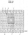
- FIG. 13 is a flowchart showing a process for controlling the known cleaner of FIG. 11, and FIG. 14 is a schematic view showing the trace of wheels of the known cleaner resulting from a travelling and cleaning operation by means of the process of FIG. 13.
- FIG. 14 there is an obstacle x disposed at a center portion of the rectangular cleaning region which is to be cleaned by the cleaner of FIG. 11.
- the user first manipulates the manipulating part 33 in order to select a learning travel mode,then remotely controls the cleaner by means of a remote controller in order to locate the cleaner at a start position 8.
- a set button of the manipulating part 33 is manipulated in order to set the two-dimensional coordinates (xo and yo) of the start position S and a reference angle ⁇ o in the path direction of the cleaner.
- the cleaner travels along the outer paths represented at the phantom line of FIG. 14 in accordance with a remote control by virtue of the remote control transmitter 34, thereby starting the learning travel step of the control process.
- the position discriminating circuit 32 determines the present position of the cleaner in the type of x and y coordinates and an angle ⁇ in the path direction, then outputs electric signals corresponding to the present position and the angle ⁇ to the CPU 47 wherein the present position and the angle ⁇ are stored in the RAM 50.
- the CPU 47 Upon accomplishing the learning travel step of the cleaner 30, the CPU 47 divides the cleaning region by a unit distance, that is, a width "W" of the cleaner 30, parallel with the x-axis and the y axis of the two-dimensional reference system, thereby dividing the cleaning region into n cleaning blocks, then stores the n blocks on a memory map in the RAM 50.
- the user locates the cleaner 30 at the start position S or at a position A near the start position S, then manipulates the manipulating part 33 in order to change the operational mode of the cleaner 30 from the learning travel mode into an unmanned travel mode.
- the motor driving part 41 drives the wheel motors 38a and 38b under the control of the control circuit 31, thereby causing the cleaner 30 to travel along a first travelling path.
- the suction motor 40 drives the dust suction part 39 in order to perform the cleaning operation.
- the cleaner 30 automatically and sequentially travels along a first column of the cleaning blocks which includes the position A.
- the CPU 47 stores the cleaning blocks, on which blocks the cleaner 30 has passed, simultaneously with erasing the number of said blocks, on which the cleaner 30 has passed, from the total number of the total blocks which have been stored in the RAM 50.
- the CPU 47 controls the cleaner 30 in order to sequentially travel along the next column.
- the CPU 47 Upon sensing the obstacle X disposed at the F position, the CPU 47 changes the path direction of the cleaner 30 in order to allow the cleaner to travel along columns of the cleaning blocks which are not yet cleaned. At the same, time, the CPU 47 stores in the RAM 50 the cleaning blocks, on which blocks the obstacle X is disposed, thereby making it impossible to clean said blocks, then controls the cleaner 30 to repeatedly travel, under a reciprocating motion, between the obstacle X and the outline of the cleaning region. Then upon determining that the obstacle X is not sensed, the CPU 47 controls the cleaner 30 to simply travel along a straight column in order to each a B position.
- the obstacle sensor 42 and the position discriminating circuit 32 Upon reaching the B position, the obstacle sensor 42 and the position discriminating circuit 32 outputs respective signals to the CPU 47, said signals informing of a condition that there are several cleaning blocks which are not yet cleaned in the right side of the B position.
- the CPU 47 stores the two-dimensional coordinates of the B position in the RAM 50, then controls the cleaner 30 to repeatedly travel, under the reciprocating motion, between the obstacle X and the outline of the cleaning region, thereby causing the cleaner to reach the C position. Thereafter, the cleaner 30 is controlled in order to return to the D position, then travels, in the same manner as above-described, along the remaining columns of the cleaning blocks which are to be cleaned thereby. In result, the cleaner 30 reaches the position G in order to stop the travelling and cleaning operation thereof.
- the cleaning region after having been designated by performance of the learning travel step is divided by a plurality of x axis and y axis on the basis of an unit distance, that is, the width of the cleaner, into n regular square cleaning blocks.
- the blocks are stored on a memory map provided in a RAM of control circuit.
- the CPU upon storing the cleaning region in the RAM by storing the cleaning blocks is the same number of memory locations as that of the blocks, the CPU stores data for cleaning accomplishment of a cleaning block, on which block the cleaner is located, in the memory location of said cleaning block.
- the known method has disadvantage in that there have to be provided n memory locations corresponding to the n cleaning blocks, thereby causing the memory capacity to need to unnecessarily increase.
- the number of the cleaning blocks increases in proportion to the area of the cleaning region, so that the known method has another disadvantage is that the cleaning region is obliged to be limited due to the limited memory capacity.
- the longitudinal and lateral distances of the cleaning region are divided by the unit distance, thus, there may be a remaining region which remains out of the divided blocks, for example, the remaining region which remains out of the 13 x 13 cleaning blocks of FIG. 14, said remaining region being represented at the deviant lined portion.
- the known method has another disadvantage in that the cleaner does not travel along the remaining region so that the region can not be cleaned.
- the known method has anothre disadvantage in that the cleaner can not efficiently clean the boundary regions between respective blocks as the regions are out of the cleaning effect of the cleaner.
- an object of this invention to provide a method for automatically controlling a travelling and cleaning operation of a vacuum cleaner in which the above disadvantages can be overcome, and in which a cleaning region is designated by using data for sectional distances of travelling paths of an outline of the cleaning region and path directions, then the cleaner is controlled by means of a control device in order to travel along the designated cleaning region in accordance with a control of the control device by using data corresponding to the cleaning region, thereby causing the cleaning region not to be limited by the memory capacity of a storage device of the control device, thus causing the cleaner to automatically perform a travelling and cleaning operation for a cleaning region regardless of dimensions of the cleaning regions.
- a method for automatically controlling a travelling and cleaning operation of a vacuum cleaner comprising: a learning travel step for calculating straight travelling distances of respective outline paths of a cleaning region and path directions of next travelling paths after a 90° turning right or left, then storing said straight travelling distances of the outline paths and said path directions of the next travelling paths after the 90° turning right or left in a storage device together with the total number of the outline paths; a two-dimensional coordinates calculating step for determining respective positions of straight division lines on the basis of 90° turning points by using data corresponding to the straight travelling distances and the path directions, each of which straight division lines parallels the x-axis or the y-axis, then calculating two-dimensional coordinates of cleaning blocks which are capable of determining positions and areas of respective cleaning blocks which are divided by said straight division lines; a cleaning block discriminating step for discriminating, on the basis of said two-dimensional coordinates of the cleaning blocks, a plurality of integrated cleaning regions each comprising a
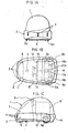
- FIGS. 1A to 1C are a front view a plane view and a side view of a vacuum cleaner in accordance with the present invention, respectively, the cleaner comprises a main body 1 which is encircled by a bumper 2.
- the bumper 2 is provided with a plurality of obstacle sensors 3 mounted thereon in order to sense an obstacle in a travelling path by transmitting and receiving an ultrasonic wave signal.
- the cleaner is provided with a front wheel 4 and a pair of rear wheels 5a and 5b mounted under a front portion and both side portions of the main body 1.
- the main body 1 is equipped in a front portion thereof with a dust suction part 6, a dust suction chamber 7 and a suction motor 8.
- the rear wheels 5a and 5b are connected to reduction gears 9a and 9b, a pair of reversible driving motors 10a and 10b and a pair of distance sensors 11a and 11b for sensing travelling distance of the cleaner on the basis of resolutions of the rear wheels 5a and 5b.
- the main body 1 is provided with a control device 12 for performing the automatic control for the travelling and cleaning operation of the cleaner.
- the control device 12 has the same construction as that of the control circuit 31 of the above-mentioned known cleaner of FIG. 11. Additionally, the main body 1 of the cleaner is provided therein with a pair of electric powor sources for supplying electric power for the suction motor 8, the reversible wheel driving motors 10a and 10b and the control device 12.
- FIG. 2 is a flowchart showing a main process for automatically controlling the travelling and cleaning operation of the cleaner of FIGS. 1A to 1C
- the cleaner first travels along outline paths of the cleaning region from a start position to an end position under a remote control by virtue of a remote controller, thereby accomplishing a designation for the cleaning region which is to be cleaned by the cleaner.
- the cleaner is controlled to travel along the outline of the cleaning region by travelling along a plurality of straight travelling paths, and turning at 9O° turning right positions and at 90° turning left positions.
- the cleaner upon receiving a 90° turning left or right control signal from the remote controller during travelling along a straight travelling path starting from the start position SP, the cleaner turns in 90° turning right or 90° turning left, then travels along another straight travelling path.
- the cleaner is controlled by means of the remote-controller to travel along the remaining outline paths of the cleaning region until the cleaner reaches the end position EP, thereby accomplishing the whole travelling along the outline paths of the cleaning region.
- the main process for automatically controlling the travelling and cleaning operation of the cleaner comprises a learning travel step 60, a two-dimensional coordinates calculating step 61, a cleaning block discriminating step 62 and a practical cleaning step 63.
- the control device 12 calculates straight travelling distances PL(i) of respective outline paths of the cleaning region and path directions PD(i) of the next travelling paths after the 90° turning right or left, when stores the straight travelling distances PL(i) of the outline paths and respective path directions PD(i) of the next travelling paths after the 90° turning right or left in a RAM thereof together with the total number mi of the outline paths.
- the control device 12 determines respective positions of straight lines on the basis of the 90° turning points by using data corresponding to the straight travelling distances PL(i) and the path directions PD(i), each of which straight lines parallels the x-axis or the y-axis, then calculates two-dimensional coordinates x(k), y(j), the total line number "mk” of longitudinal division lines and the total line number "mj" of lateral division lines of the cleaning blocks, said two-dimensional coordinates x(k), y(j) being capable of determining positions and areas of respective cleaning blocks B(i,j) of the cleaning region.
- the control device 12 delimits, on the basis of the two-dimensional coordinates x(k), y(j) of the cleaning blocks B(i,j), a plurality of integrated cleaning regions each comprising a plurality of sequential cleaning blocks disposed between a cleaning block S(j)(L), that is, a cleaning start block of which the lower end coincides with an outline path of the cleaning region to another cleaning block E(j)(L), that is, a cleaning end block of which upper end coincides with an outline path of the cleaning region, then determines the cleaning start block S(j)(L) and the cleaning end block E(j)(L).
- FIGS. 3 and 7 are a flowchart showing a process for performing the learning travel step 60 of FIG. 2 and views showing an example of the learning travel step 60 of FIG. 3, the user controls the cleaner to locate at the start position SP by using a remote controller, then starts the cleaner after having selected the learning travel mode of the cleaner (step 70).
- the control device 12 controls the wheel driving motors 10a and 10b to drive the wheels 5a and 5b, thereby causing the cleaner to travel along a first straight path of the cleaning region from the start position SP.
- the distance sensors 11a and 11b sense the travelling distance of the cleaner as the cleaner travels, then output electric signals corresponding to the travelling distance to the control device 12.
- the control device 12 processes the signals in the same manner as that of the known control circuit 31 of FIG. 11.
- control device 12 Upon receiving a 90° turning left signal after accomplishing the travelling along the first straight travelling path in a predetermined distance PL(1) (step 72), the control device 12 stores the straight travelling distance PL(1) along the first travel path path in the RAM thereof, said distance PL(1) resulting from the processing thereof for the input signals applied from the distance sensors 11a and 11b thereto (steps 73 and 74).
- control device 12 determines whether the path direction PD(i) is "-1" (step 77). At this time, the path direction PD(2) in the second travelling path is "-1" as described above, thus, the control device 12 substitutes "3" for the path direction PD(2) (step 78), then controls the cleaner to turn in 90° turning left, thereafter, sequentially controls the cleaner to travel along the second straight path (step 79).
- the control device 12 simply performs the step 79 in order to control the cleaner to turn in 90° turning left, thereafter, sequentially travel along the second straight path.
- control device 12 stores the straight travelling distance PL(2) in the second travelling path in the RAM thereof, said distance PL(2) resulting from processing thereof for input signals applied from the distance sensors 11a and 11b thereto (steps 81 and 82).
- the straight travelling distance in the second travelling path is "15"
- "3" is substituted for "i”
- the control device 12 determines whether the path direction PD(i) is "4" (step 85). At this time, the path direction PD(3) in the third straight travelling path is "4" as described above, thus, the control device 12 substitutes "0" for the path direction PD(3) (step 86), then controls the cleaner to turn in 90° turning right, thereafter, sequentially controls the cleaner to travel along the third straight travelling path (step 87).
- "4" is substituted for "i"
- the path direction PD(3) in the second travelling path is "0", resulting from the above-described substitution, so that the path direction PD(4) in the fourth straight travelling path is determined as "1".
- the control device 12 determines whether the path direction PD(i) is "4" (step 85). At this time, the path direction PD(4) in the fourth straight travelling path was determined as "1" as described above, thus, the control device 12 simply performs the step 87 without any substitution in order to control the cleaner to turn in 90° turning right, thereafter, sequentially travel along the fourth straight travelling path (step 87). At this time, the path direction PD(4) in the fourth straight travelling path is set as "1".
- the control device 12 calculates respective path directions PD(i) and straight travelling distance PL(i) for respective straight travelling paths, that is, the first to eight straight travelling paths as shown in FIG. 7A.
- the calculated path directions PD(i) and the straight travelling distances PL(i) for respective straight travelling paths are described in a table of FIG. 7D.
- the total number. "mi" of the straight travelling paths is calculated as "8".
- the control device 12 ends the learning travel step 60.
- FIG. 4 is a flowchart showing a process for performing the two-dimensional coordinates calculating step 61 of FIG. 2
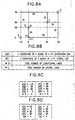
- FIGS. 8A to 8D are views showing an example of two-dimensional coordinates calculating step of FIG. 4, respectively.
- the control device 12 calculates two-dimensional coordinates for eight travelling paths.
- the calculated two-dimensional coordinates that is, x-coordinates and y-coordinates of longitudinal division lines and lateral division lines of the cleaning blocks are described in a table of FIG. 8C.
- the x-coordinates and y-coordinates of longitudinal division lines and lateral division lines of the cleaning blocks are sequentially classified according to the magnitude thereof, that is, in an order from the relatively smaller value of coordinate to the relatively larger value of each coordinate (step 104).
- the classified x-coordinates and y-coordinates are described in a table of FIG. 8D.
- the control device 12 calculates two-dimensional coordinates of cross points of the lateral division lines and the longitudinal division lines of the cleaning blocks.
- the two-dimensional coordinate of the A cross point of FIG. 8A is described as A(-15,0).
- the two-dimensional coordinate of the B cross point of FIG. 8A is described as B(0,20).
- the two-dimensional coordinate of the C cross point of FIG. 8A is described as C(35,30) and the two-dimensional coordinate of the D cross point of FIG. 8A is described as D(0,20).
- the cleaning region of FIG. 8A is divided into nine cleaning blocks in total. however, by means of the two-dimensional coordinates, seven cleaning blocks of the nine blocks are to be cleaned by the cleaner.
- FIG. 5 is a flowchart showing a process for performing the cleaning block discriminating step 62 of FIG. 2
- FIGS. 9A to 9E are views showing an example of the cleaning block discriminating step 62 of FIG. 5, respectively.
- FIG. 9A which is a plane view of the cleaning blocks of the cleaning region
- FIGS. 9B and 9C a plurality of cleaning blocks disposed in a L-th layer of the j-th row are discriminated as an integrated cleaning region, it is possible to calculate the column number S(i)(L) of a cleaning start block of the integrated cleaning region and the column number E(i)(L) of a cleaning end block the integrated cleaning region, as shown in FIGS. 9B and 9C.
- the control device 12 determines whether the lower end of the cleaning block B(1,1) of the first column and the first row is coincide with the travelling path of the cleaning region which has been determined in the above leaning travel step (step 111).
- the control device 12 increases the layer number "L” by adding “1” (step 114), then, compares the layer number "L” with the maximum layer number ML in order to determine whether the layer number "L” is larger than the maximum layer number ML (step 115).
- control device 12 determines whether the upper end of the cleaning block B(2,1) of the second column and the first row is coincide with the travelling path of the cleaning region which has been determined in the above leaning travel step (step 118). At this time, the upper end of the cleaning block B(2,1) is not coincide with the travelling path of the cleaning region as shown in FIG. 9A, the control device 12 increases the "i" value by adding "1" (step 119), then, determines whether the upper end of the cleaning block B(3,1) of the third column and the first row is coincide with the travelling path of the cleaning region which has been determined in the above learning travel step (step 118).
- the two-dimensional coordinates of the cleaning start blocks are described as B(1,1),B(3,1), B(1,2) and B(1,3)
- the two-dimensional coordinates of the cleaning end blocks are described as B(1,1),B(4,1), B(4,2) and B(3,3).
- the cleaning start block and the cleaning end block are determined from the column numbers S(i)(L) and E(j)(L) of the cleaning start block and the cleaning end block which are determined in the above-mentioned cleaning block discriminating step.
- FIG. 6 is a flowchart showing the process for performing the practical cleaning step 63 of FIG. 2
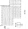
- FIG. 10 is a schematic view showing the trace of wheels of the cleaner resulting from the travelling and cleaning operation by the process of FIG. 6.
- the control device 12 controls the cleaner to start the travelling operation along the first travelling path from the start position SP toward the left side lower end position of the cleaning start block B[S(j)(L),j], that is, B(2,1), which is an initial cleaning position of the first integrated cleaning region which is to be first cleaned (step 131).
- B[S(j)(L),j] B(2,1).
- B[E(j)(L),j] B(3,1).
- control device 12 calculates the lateral distance H and the longitudinal distance V of the above first integrated cleaning region which comprises the cleaning start block B(2,1) and the cleaning end block B(3,1) (step 132).
- control device 12 increase the "i" value by adding “2" (step 136), then determines whether the "i” value is equal to the minimum even number "n” (step 137). If the "i" value is not equal to the minimum even number "n” the control device 12 repeatedly performs the steps 134 to 137 until the "i" value is equal to the minimum even number "n".
- control device 12 sets the "i" value as "0" (step 141), then again performs the step 131 in order to control the cleaner to return to the left side lower end position of the cleaning start block B[S(j)(L),j] of a second integrated cleaning region which is to be second cleaned and comprises the cleaning blocks B(1,2), B(2,2) and B(3,2) of the second row.
- control device 12 controls the cleaner to travel along the second intergrated cleaning region comprising the cleaning blocks B(1,2), B(2,2) and B(3,2) of the second row is the same manner as described above.
- control device 12 controls the cleaner to travel along the third integrated cleaning region comprising the cleaning blocks B(1,3) and B(2,3) of the third row in the same manner as described above.
- control device 12 controls the cleaner to efficiently performs the travelling and cleaning operation thereof for the cleaning region comprising the two layers of cleaning blocks B(1,1), B(3,2) and B(4,1), as shown in FIG. 9D.
- the present invention provides a method for automatically controlling a travelling and cleaning operation of a vacuum cleaner in which a cleaning region is designated by using data corresponding to sectional distances of travelling paths of the outline of the cleaning region and path directions, then the cleaner is controlled by means of a control device in order to travel along the designated cleaning region in accordance with a control by using data corresponding to the cleaning region, thereby providing advantage in that the cleaning region is not limited by the memory capacity of a control device so that the cleaner automatically performs a travelling and cleaning operation for a cleaning region regardless of dimensions of the cleaning regions.
- the method of this invention provides another advantage in that the cleaner is controlled to travel along the sequential cleaning blocks simultaneously with overlapping a predetermined width of each cleaning block, thereby improving the cleaning effect of the cleaner for the cleaning region.
Landscapes
- Engineering & Computer Science (AREA)
- Aviation & Aerospace Engineering (AREA)
- Radar, Positioning & Navigation (AREA)
- Remote Sensing (AREA)
- Physics & Mathematics (AREA)
- General Physics & Mathematics (AREA)
- Automation & Control Theory (AREA)
- Control Of Position, Course, Altitude, Or Attitude Of Moving Bodies (AREA)
- Electric Vacuum Cleaner (AREA)
- Manipulator (AREA)
Applications Claiming Priority (2)
| Application Number | Priority Date | Filing Date | Title |
|---|---|---|---|
| KR2010090 | 1990-12-07 | ||
| KR1019900020100A KR930000081B1 (ko) | 1990-12-07 | 1990-12-07 | 청소기의 자동 청소방법 |
Publications (3)
| Publication Number | Publication Date |
|---|---|
| EP0490736A2 true EP0490736A2 (de) | 1992-06-17 |
| EP0490736A3 EP0490736A3 (en) | 1992-12-09 |
| EP0490736B1 EP0490736B1 (de) | 1997-02-05 |
Family
ID=19307180
Family Applications (1)
| Application Number | Title | Priority Date | Filing Date |
|---|---|---|---|
| EP91403301A Expired - Lifetime EP0490736B1 (de) | 1990-12-07 | 1991-12-06 | Verfahren zur automatischen Steuerung eines reinigenden Vorganges eines Staubsaugers |
Country Status (5)
| Country | Link |
|---|---|
| US (1) | US5353224A (de) |
| EP (1) | EP0490736B1 (de) |
| JP (1) | JPH04333902A (de) |
| KR (1) | KR930000081B1 (de) |
| DE (1) | DE69124587T2 (de) |
Cited By (15)
| Publication number | Priority date | Publication date | Assignee | Title |
|---|---|---|---|---|
| GB2278937A (en) * | 1993-06-08 | 1994-12-14 | Samsung Electronics Co Ltd | Robot vacuum cleaner |
| WO1996001072A1 (fr) * | 1994-07-04 | 1996-01-18 | Solar And Robotics S.A. | Dispositif et engin automatique de depoussierage de sol |
| EP0786229A3 (de) * | 1996-01-25 | 1998-05-13 | Penguin Wax Co., Ltd. | Bodenbearbeitungmaschine mit einem an einem Fahrzeug mit Eigenantrieb angeordneten Werkzeug |
| EP0971276A1 (de) * | 1998-07-10 | 2000-01-12 | Fuji Jukogyo Kabushiki Kaisha | Gerät und Verfahren zur Steuerung eines autonom fahrenden Fahrzeugs |
| WO2000008535A1 (en) * | 1998-08-06 | 2000-02-17 | Caterpillar Inc. | Method and apparatus for establishing a perimeter defining an area to be traversed by a mobile machine |
| FR2785839A1 (fr) * | 1998-11-17 | 2000-05-19 | Seb Sa | Aspirateur mobile autonome et son procede de controle |
| FR2861855A1 (fr) * | 2003-11-03 | 2005-05-06 | Wany Sa | Procede et dispositif pour balayer une surface de maniere statistique |
| EP1557730A1 (de) * | 2004-01-22 | 2005-07-27 | Alfred Kärcher GmbH & Co. KG | Bodenbearbeitungsgerät sowie Verfahren zu dessen Steuerung |
| RU2308214C1 (ru) * | 2005-04-23 | 2007-10-20 | ЭлДжи ЭЛЕКТРОНИКС ИНК. | Способ движения робота-уборщика (варианты) |
| RU2312579C2 (ru) * | 2005-07-22 | 2007-12-20 | ЭлДжи ЭЛЕКТРОНИКС ИНК. | Домашняя сетевая система, использующая самодвижущийся робот (варианты) |
| CN102789232A (zh) * | 2011-05-16 | 2012-11-21 | 苏州宝时得电动工具有限公司 | 自动行走设备及其控制方法 |
| CN102871605A (zh) * | 2012-08-23 | 2013-01-16 | 群耀光电科技(苏州)有限公司 | 清洁机器人判断打扫区域的方法、装置及清洁机器人 |
| CN106575121A (zh) * | 2014-08-06 | 2017-04-19 | 阿尔弗雷德·凯驰两合公司 | 用于处理地表面的方法和地面处理设备 |
| CN107491077A (zh) * | 2017-09-22 | 2017-12-19 | 衢州职业技术学院 | 一种基于手机app控制的室内清扫机器人 |
| US10123674B2 (en) | 2016-09-09 | 2018-11-13 | International Business Machines Corporation | Cognitive vacuum cleaner with learning and cohort classification |
Families Citing this family (113)
| Publication number | Priority date | Publication date | Assignee | Title |
|---|---|---|---|---|
| JP3140900B2 (ja) * | 1993-12-20 | 2001-03-05 | シャープ株式会社 | 自動走行式電気掃除機 |
| JP3346513B2 (ja) * | 1994-07-01 | 2002-11-18 | ミノルタ株式会社 | マップ記憶方法及びそのマップを使用する経路作成方法 |
| IL113913A (en) * | 1995-05-30 | 2000-02-29 | Friendly Machines Ltd | Navigation method and system |
| US6830120B1 (en) * | 1996-01-25 | 2004-12-14 | Penguin Wax Co., Ltd. | Floor working machine with a working implement mounted on a self-propelled vehicle for acting on floor |
| US6574536B1 (en) | 1996-01-29 | 2003-06-03 | Minolta Co., Ltd. | Moving apparatus for efficiently moving on floor with obstacle |
| US5935179A (en) * | 1996-04-30 | 1999-08-10 | Aktiebolaget Electrolux | System and device for a self orienting device |
| IL124413A (en) * | 1998-05-11 | 2001-05-20 | Friendly Robotics Ltd | System and method for area coverage with an autonomous robot |
| US6339735B1 (en) | 1998-12-29 | 2002-01-15 | Friendly Robotics Ltd. | Method for operating a robot |
| US7155308B2 (en) | 2000-01-24 | 2006-12-26 | Irobot Corporation | Robot obstacle detection system |
| US8412377B2 (en) | 2000-01-24 | 2013-04-02 | Irobot Corporation | Obstacle following sensor scheme for a mobile robot |
| US8788092B2 (en) | 2000-01-24 | 2014-07-22 | Irobot Corporation | Obstacle following sensor scheme for a mobile robot |
| US6956348B2 (en) | 2004-01-28 | 2005-10-18 | Irobot Corporation | Debris sensor for cleaning apparatus |
| US7571511B2 (en) | 2002-01-03 | 2009-08-11 | Irobot Corporation | Autonomous floor-cleaning robot |
| US6690134B1 (en) | 2001-01-24 | 2004-02-10 | Irobot Corporation | Method and system for robot localization and confinement |
| US6883201B2 (en) | 2002-01-03 | 2005-04-26 | Irobot Corporation | Autonomous floor-cleaning robot |
| SE518483C2 (sv) * | 2001-02-28 | 2002-10-15 | Electrolux Ab | Hjulupphängning för en självgående städapparat |
| SE518482C2 (sv) * | 2001-02-28 | 2002-10-15 | Electrolux Ab | Hinderavkänningssystem för en självgående städapparat |
| SE518683C2 (sv) | 2001-03-15 | 2002-11-05 | Electrolux Ab | Förfarande och anordning för positionsbestämning av en autonom apparat |
| SE0100924D0 (sv) * | 2001-03-15 | 2001-03-15 | Electrolux Ab | Energy-efficient navigation of an autonomous surface treatment apparatus |
| KR100437372B1 (ko) * | 2001-04-18 | 2004-06-25 | 삼성광주전자 주식회사 | 이동통신망을 이용한 로봇 청소 시스템 |
| ATE510247T1 (de) | 2001-06-12 | 2011-06-15 | Irobot Corp | Verfahren und system zur multimodalen bedeckung für einen autonomen roboter |
| US7429843B2 (en) | 2001-06-12 | 2008-09-30 | Irobot Corporation | Method and system for multi-mode coverage for an autonomous robot |
| US8396592B2 (en) | 2001-06-12 | 2013-03-12 | Irobot Corporation | Method and system for multi-mode coverage for an autonomous robot |
| AU2002341358A1 (en) * | 2001-09-26 | 2003-04-07 | Friendly Robotics Ltd. | Robotic vacuum cleaner |
| IL145680A0 (en) | 2001-09-26 | 2002-06-30 | Friendly Robotics Ltd | Robotic vacuum cleaner |
| US9128486B2 (en) | 2002-01-24 | 2015-09-08 | Irobot Corporation | Navigational control system for a robotic device |
| US8386081B2 (en) * | 2002-09-13 | 2013-02-26 | Irobot Corporation | Navigational control system for a robotic device |
| US8428778B2 (en) | 2002-09-13 | 2013-04-23 | Irobot Corporation | Navigational control system for a robotic device |
| EP1547361B1 (de) | 2002-09-13 | 2016-04-06 | iRobot Corporation | Navigationssteuersystem für eine robotische einrichtung |
| US7170252B2 (en) * | 2003-07-23 | 2007-01-30 | Renesas Technology Corporation | Location aware automata |
| KR100533829B1 (ko) * | 2003-07-29 | 2005-12-07 | 삼성광주전자 주식회사 | 공기청정로봇 및 그 시스템 |
| FR2861856B1 (fr) * | 2003-11-03 | 2006-04-07 | Wany Sa | Procede et dispositif pour balayer une surface de maniere automatique |
| US7332890B2 (en) | 2004-01-21 | 2008-02-19 | Irobot Corporation | Autonomous robot auto-docking and energy management systems and methods |
| DE112005000738T5 (de) | 2004-03-29 | 2007-04-26 | Evolution Robotics, Inc., Pasadena | Verfahren und Vorrichtung zur Positionsbestimmung unter Verwendung von reflektierten Lichtquellen |
| WO2006002385A1 (en) | 2004-06-24 | 2006-01-05 | Irobot Corporation | Programming and diagnostic tool for a mobile robot |
| US7706917B1 (en) | 2004-07-07 | 2010-04-27 | Irobot Corporation | Celestial navigation system for an autonomous robot |
| US8972052B2 (en) | 2004-07-07 | 2015-03-03 | Irobot Corporation | Celestial navigation system for an autonomous vehicle |
| US7389156B2 (en) | 2005-02-18 | 2008-06-17 | Irobot Corporation | Autonomous surface cleaning robot for wet and dry cleaning |
| KR101247933B1 (ko) | 2005-02-18 | 2013-03-26 | 아이로보트 코퍼레이션 | 습식 및 건식 청소를 위한 자동 표면 청소 로봇 |
| US8392021B2 (en) | 2005-02-18 | 2013-03-05 | Irobot Corporation | Autonomous surface cleaning robot for wet cleaning |
| US7620476B2 (en) | 2005-02-18 | 2009-11-17 | Irobot Corporation | Autonomous surface cleaning robot for dry cleaning |
| US8930023B2 (en) | 2009-11-06 | 2015-01-06 | Irobot Corporation | Localization by learning of wave-signal distributions |
| WO2007008148A1 (en) * | 2005-07-08 | 2007-01-18 | Ab Electrolux | Robotic cleaning device |
| WO2007065034A1 (en) | 2005-12-02 | 2007-06-07 | Irobot Corporation | Modular robot |
| EP2251757B1 (de) | 2005-12-02 | 2011-11-23 | iRobot Corporation | Abdeckungsrobotermobilität |
| EP2816434A3 (de) | 2005-12-02 | 2015-01-28 | iRobot Corporation | Roboter mit autonomem Wirkungsbereich |
| ES2706729T3 (es) | 2005-12-02 | 2019-04-01 | Irobot Corp | Sistema de robot |
| KR101099808B1 (ko) | 2005-12-02 | 2011-12-27 | 아이로보트 코퍼레이션 | 로봇 시스템 |
| ES2707155T3 (es) | 2006-03-17 | 2019-04-02 | Irobot Corp | Confinamiento de robot |
| ES2583374T3 (es) | 2006-05-19 | 2016-09-20 | Irobot Corporation | Eliminación de residuos de robots de limpieza |
| TWI293555B (en) * | 2006-05-23 | 2008-02-21 | Ind Tech Res Inst | Omni-directional robot cleaner |
| US8417383B2 (en) | 2006-05-31 | 2013-04-09 | Irobot Corporation | Detecting robot stasis |
| JP2008003979A (ja) * | 2006-06-26 | 2008-01-10 | Matsushita Electric Ind Co Ltd | 自走式機器およびそのプログラム |
| EP2574265B1 (de) | 2007-05-09 | 2015-10-14 | iRobot Corporation | Kompakter Roboter mit autonomer Reichweite |
| US20090048727A1 (en) * | 2007-08-17 | 2009-02-19 | Samsung Electronics Co., Ltd. | Robot cleaner and control method and medium of the same |
| JP5073609B2 (ja) * | 2008-08-11 | 2012-11-14 | 日東電工株式会社 | 光導波路の製造方法 |
| US8800107B2 (en) | 2010-02-16 | 2014-08-12 | Irobot Corporation | Vacuum brush |
| TWI424296B (zh) * | 2010-05-25 | 2014-01-21 | Micro Star Int Co Ltd | 引導裝置及操作系統 |
| CN107422723B (zh) | 2010-12-30 | 2021-08-24 | 美国iRobot公司 | 覆盖机器人导航 |
| KR101566207B1 (ko) * | 2011-06-28 | 2015-11-13 | 삼성전자 주식회사 | 로봇 청소기 및 그 제어방법 |
| ES2610755T3 (es) | 2012-08-27 | 2017-05-03 | Aktiebolaget Electrolux | Sistema de posicionamiento de un robot |
| EP2752726B1 (de) | 2013-01-08 | 2015-05-27 | Cleanfix Reinigungssysteme AG | Bodenbehandlungsmaschine und Verfahren zum Behandeln von Bodenflächen |
| EP2986192B1 (de) | 2013-04-15 | 2021-03-31 | Aktiebolaget Electrolux | Robotischer staubsauger |
| CN105101855A (zh) | 2013-04-15 | 2015-11-25 | 伊莱克斯公司 | 具有伸出的侧刷的机器人真空吸尘器 |
| KR102099495B1 (ko) | 2013-12-19 | 2020-04-09 | 에이비 엘렉트로룩스 | 로봇 청소 장치가 장애물에 올라가는 것의 감지 |
| CN105849660B (zh) | 2013-12-19 | 2020-05-08 | 伊莱克斯公司 | 机器人清扫装置 |
| WO2015090402A1 (en) | 2013-12-19 | 2015-06-25 | Aktiebolaget Electrolux | Robotic cleaning device with perimeter recording function |
| CN105792721B (zh) | 2013-12-19 | 2020-07-21 | 伊莱克斯公司 | 以螺旋样式移动的带侧刷的机器人真空吸尘器 |
| EP3082537B1 (de) | 2013-12-19 | 2020-11-18 | Aktiebolaget Electrolux | Robotische reinigungsvorrichtung und verfahren zur bezugspunkterkennung |
| EP3084539B1 (de) | 2013-12-19 | 2019-02-20 | Aktiebolaget Electrolux | Priorisierung von reinigungsbereichen |
| JP6638987B2 (ja) | 2013-12-19 | 2020-02-05 | アクチエボラゲット エレクトロルックス | 回転側面ブラシの適応速度制御 |
| KR102116595B1 (ko) | 2013-12-20 | 2020-06-05 | 에이비 엘렉트로룩스 | 먼지통 |
| CN103767633B (zh) * | 2014-02-28 | 2016-04-20 | 柯约瑟 | 全自动位移清洁装置的移位运作系统 |
| WO2015153109A1 (en) | 2014-03-31 | 2015-10-08 | Irobot Corporation | Autonomous mobile robot |
| US20150293533A1 (en) * | 2014-04-13 | 2015-10-15 | Bobsweep Inc. | Scanned Code Instruction and Confinement Sytem for Mobile Electronic Devices |
| CN104972462B (zh) | 2014-04-14 | 2017-04-19 | 科沃斯机器人股份有限公司 | 自移动机器人避障行走方法 |
| US9764473B1 (en) | 2014-10-01 | 2017-09-19 | Bobsweep Inc. | System and method for confinement of a robotic device |
| WO2016005012A1 (en) | 2014-07-10 | 2016-01-14 | Aktiebolaget Electrolux | Method for detecting a measurement error in a robotic cleaning device |
| US9764472B1 (en) | 2014-07-18 | 2017-09-19 | Bobsweep Inc. | Methods and systems for automated robotic movement |
| EP3190938A1 (de) | 2014-09-08 | 2017-07-19 | Aktiebolaget Electrolux | Robotischer staubsauger |
| JP6443897B2 (ja) | 2014-09-08 | 2018-12-26 | アクチエボラゲット エレクトロルックス | ロボット真空掃除機 |
| US10579066B1 (en) | 2015-03-30 | 2020-03-03 | AI Incorporated | System and method for establishing virtual boundaries for robotic devices |
| US11347239B1 (en) | 2014-10-01 | 2022-05-31 | AI Incorporated | System and method for establishing virtual boundaries for robotic devices |
| US9510505B2 (en) | 2014-10-10 | 2016-12-06 | Irobot Corporation | Autonomous robot localization |
| US9516806B2 (en) | 2014-10-10 | 2016-12-13 | Irobot Corporation | Robotic lawn mowing boundary determination |
| EP3230814B1 (de) | 2014-12-10 | 2021-02-17 | Aktiebolaget Electrolux | Verwendung eines lasersensors zur bodentypdetektion |
| CN107072454A (zh) | 2014-12-12 | 2017-08-18 | 伊莱克斯公司 | 侧刷和机器人吸尘器 |
| US9420741B2 (en) | 2014-12-15 | 2016-08-23 | Irobot Corporation | Robot lawnmower mapping |
| JP6532530B2 (ja) | 2014-12-16 | 2019-06-19 | アクチエボラゲット エレクトロルックス | ロボット掃除機の掃除方法 |
| KR102339531B1 (ko) | 2014-12-16 | 2021-12-16 | 에이비 엘렉트로룩스 | 로봇 청소 장치를 위한 경험-기반의 로드맵 |
| US9538702B2 (en) | 2014-12-22 | 2017-01-10 | Irobot Corporation | Robotic mowing of separated lawn areas |
| US10545504B2 (en) | 2015-04-01 | 2020-01-28 | AI Incorporated | System and method for establishing virtual boundaries for robotic devices |
| US11099554B2 (en) | 2015-04-17 | 2021-08-24 | Aktiebolaget Electrolux | Robotic cleaning device and a method of controlling the robotic cleaning device |
| US11115798B2 (en) | 2015-07-23 | 2021-09-07 | Irobot Corporation | Pairing a beacon with a mobile robot |
| WO2017036532A1 (en) | 2015-09-03 | 2017-03-09 | Aktiebolaget Electrolux | System of robotic cleaning devices |
| US10021830B2 (en) | 2016-02-02 | 2018-07-17 | Irobot Corporation | Blade assembly for a grass cutting mobile robot |
| US10459063B2 (en) | 2016-02-16 | 2019-10-29 | Irobot Corporation | Ranging and angle of arrival antenna system for a mobile robot |
| CN108603935A (zh) | 2016-03-15 | 2018-09-28 | 伊莱克斯公司 | 机器人清洁设备以及机器人清洁设备进行陡壁检测的方法 |
| EP3439522B1 (de) | 2016-04-08 | 2023-06-07 | A&K Robotics Inc. | Zwischen manuellem und autonomem betrieb umwandelbarer autowäscher |
| JP6692204B2 (ja) * | 2016-04-15 | 2020-05-13 | 日立グローバルライフソリューションズ株式会社 | 自律走行型掃除機 |
| CN109068908B (zh) | 2016-05-11 | 2021-05-11 | 伊莱克斯公司 | 机器人清洁设备 |
| JP7243967B2 (ja) | 2017-06-02 | 2023-03-22 | アクチエボラゲット エレクトロルックス | ロボット清掃デバイスの前方の表面のレベル差を検出する方法 |
| US11470774B2 (en) | 2017-07-14 | 2022-10-18 | Irobot Corporation | Blade assembly for a grass cutting mobile robot |
| JP2020533056A (ja) | 2017-09-07 | 2020-11-19 | シャークニンジャ オペレーティング エルエルシー | ロボットクリーナー |
| JP6989210B2 (ja) | 2017-09-26 | 2022-01-05 | アクチエボラゲット エレクトロルックス | ロボット清掃デバイスの移動の制御 |
| WO2019195483A1 (en) | 2018-04-03 | 2019-10-10 | Sharkninja Operating Llc | Time of flight sensor arrangement for robot navigation and methods of localization using same |
| AU2020100041A4 (en) | 2019-01-11 | 2020-02-20 | Bissell Inc. | Artificial barrier for autonomous floor cleaner |
| CN111562777B (zh) * | 2019-01-29 | 2024-04-19 | 北京奇虎科技有限公司 | 一种扫地机器人的清扫路径规划方法和装置 |
| CN110251009A (zh) * | 2019-07-25 | 2019-09-20 | 深圳市捷扬讯科电子有限公司 | 一种扫地机器人的清扫路径管理方法及系统 |
| DE102019125469A1 (de) * | 2019-09-23 | 2021-03-25 | Hako Gmbh | Verfahren zum Reinigen einer Bodenfläche mit einer Bodenreinigungsmaschine |
| CN111415464A (zh) * | 2020-04-26 | 2020-07-14 | 苏州步进科技有限公司 | 一种分离装置及自动售卖机 |
| CN112419346B (zh) * | 2020-11-02 | 2024-07-09 | 尚科宁家(中国)科技有限公司 | 清洁机器人及分区方法 |
| CN112815945B (zh) * | 2020-12-31 | 2024-11-01 | 无锡太机脑智能科技有限公司 | 增大角落清洁面积的无人洗地机路径规划方法及系统 |
Family Cites Families (8)
| Publication number | Priority date | Publication date | Assignee | Title |
|---|---|---|---|---|
| DE2364002C2 (de) * | 1973-12-21 | 1983-02-24 | Frey, Helmut, Dr.jur., 8000 München | Orientierungsvorrichtung für ein Gerätesystem, das sich zur Bearbeitung einer Fläche auf dieser bewegt |
| US4674048A (en) * | 1983-10-26 | 1987-06-16 | Automax Kabushiki-Kaisha | Multiple robot control system using grid coordinate system for tracking and completing travel over a mapped region containing obstructions |
| NO864109L (no) * | 1985-10-17 | 1987-04-21 | Knepper Hans Reinhard | Fremgangsmaate for automatisk foering av selvgaaende gulvrengjoeringsmaskiner samt gulvrengjoeringsmaskin for utfoerelse av fremgangsmaaten. |
| JPH0827651B2 (ja) * | 1987-05-19 | 1996-03-21 | 三洋電機株式会社 | 作業車の作業経路決定装置 |
| US4962453A (en) * | 1989-02-07 | 1990-10-09 | Transitions Research Corporation | Autonomous vehicle for working on a surface and method of controlling same |
| JP2815606B2 (ja) * | 1989-04-25 | 1998-10-27 | 株式会社トキメック | コンクリート床仕上ロボットの制御方式 |
| JPH0313611A (ja) * | 1989-06-07 | 1991-01-22 | Toshiba Corp | 自動清掃装置 |
| US5020620A (en) * | 1989-09-28 | 1991-06-04 | Tennant Company | Offsetting the course of a laser guided vehicle |
-
1990
- 1990-12-07 KR KR1019900020100A patent/KR930000081B1/ko not_active Expired - Fee Related
-
1991
- 1991-12-05 US US07/804,236 patent/US5353224A/en not_active Expired - Fee Related
- 1991-12-06 DE DE69124587T patent/DE69124587T2/de not_active Expired - Fee Related
- 1991-12-06 EP EP91403301A patent/EP0490736B1/de not_active Expired - Lifetime
- 1991-12-07 JP JP3323495A patent/JPH04333902A/ja active Pending
Cited By (23)
| Publication number | Priority date | Publication date | Assignee | Title |
|---|---|---|---|---|
| GB2278937A (en) * | 1993-06-08 | 1994-12-14 | Samsung Electronics Co Ltd | Robot vacuum cleaner |
| GB2278937B (en) * | 1993-06-08 | 1998-01-14 | Samsung Electronics Co Ltd | Robot cleaner |
| WO1996001072A1 (fr) * | 1994-07-04 | 1996-01-18 | Solar And Robotics S.A. | Dispositif et engin automatique de depoussierage de sol |
| EP0786229A3 (de) * | 1996-01-25 | 1998-05-13 | Penguin Wax Co., Ltd. | Bodenbearbeitungmaschine mit einem an einem Fahrzeug mit Eigenantrieb angeordneten Werkzeug |
| EP0971276A1 (de) * | 1998-07-10 | 2000-01-12 | Fuji Jukogyo Kabushiki Kaisha | Gerät und Verfahren zur Steuerung eines autonom fahrenden Fahrzeugs |
| US6480768B1 (en) | 1998-07-10 | 2002-11-12 | Fuji Jukogyo Kabushiki Kaisha | Control apparatus for autonomous traveling vehicle and method thereof |
| WO2000008535A1 (en) * | 1998-08-06 | 2000-02-17 | Caterpillar Inc. | Method and apparatus for establishing a perimeter defining an area to be traversed by a mobile machine |
| US6112143A (en) * | 1998-08-06 | 2000-08-29 | Caterpillar Inc. | Method and apparatus for establishing a perimeter defining an area to be traversed by a mobile machine |
| FR2785839A1 (fr) * | 1998-11-17 | 2000-05-19 | Seb Sa | Aspirateur mobile autonome et son procede de controle |
| EP1003088A1 (de) * | 1998-11-17 | 2000-05-24 | Seb S.A. | Selbsständig beweglicher Staubsauger und Verfahren zur Steuerung desselben |
| FR2861855A1 (fr) * | 2003-11-03 | 2005-05-06 | Wany Sa | Procede et dispositif pour balayer une surface de maniere statistique |
| WO2005045544A1 (fr) * | 2003-11-03 | 2005-05-19 | Wany Sa | Procede et systeme pour balayer une surface de maniere statistique |
| EP1557730A1 (de) * | 2004-01-22 | 2005-07-27 | Alfred Kärcher GmbH & Co. KG | Bodenbearbeitungsgerät sowie Verfahren zu dessen Steuerung |
| RU2308214C1 (ru) * | 2005-04-23 | 2007-10-20 | ЭлДжи ЭЛЕКТРОНИКС ИНК. | Способ движения робота-уборщика (варианты) |
| RU2312579C2 (ru) * | 2005-07-22 | 2007-12-20 | ЭлДжи ЭЛЕКТРОНИКС ИНК. | Домашняя сетевая система, использующая самодвижущийся робот (варианты) |
| CN102789232A (zh) * | 2011-05-16 | 2012-11-21 | 苏州宝时得电动工具有限公司 | 自动行走设备及其控制方法 |
| CN102789232B (zh) * | 2011-05-16 | 2015-02-04 | 苏州宝时得电动工具有限公司 | 自动行走设备及其控制方法 |
| CN102871605A (zh) * | 2012-08-23 | 2013-01-16 | 群耀光电科技(苏州)有限公司 | 清洁机器人判断打扫区域的方法、装置及清洁机器人 |
| CN102871605B (zh) * | 2012-08-23 | 2016-02-03 | 群耀光电科技(苏州)有限公司 | 清洁机器人判断打扫区域的方法、装置及清洁机器人 |
| CN106575121A (zh) * | 2014-08-06 | 2017-04-19 | 阿尔弗雷德·凯驰两合公司 | 用于处理地表面的方法和地面处理设备 |
| CN106575121B (zh) * | 2014-08-06 | 2020-04-03 | 阿尔弗雷德·卡赫欧洲两合公司 | 用于处理地表面的方法和地面处理设备 |
| US10123674B2 (en) | 2016-09-09 | 2018-11-13 | International Business Machines Corporation | Cognitive vacuum cleaner with learning and cohort classification |
| CN107491077A (zh) * | 2017-09-22 | 2017-12-19 | 衢州职业技术学院 | 一种基于手机app控制的室内清扫机器人 |
Also Published As
| Publication number | Publication date |
|---|---|
| KR930000081B1 (ko) | 1993-01-08 |
| KR920011428A (ko) | 1992-07-24 |
| US5353224A (en) | 1994-10-04 |
| EP0490736A3 (en) | 1992-12-09 |
| DE69124587T2 (de) | 1997-09-11 |
| JPH04333902A (ja) | 1992-11-20 |
| EP0490736B1 (de) | 1997-02-05 |
| DE69124587D1 (de) | 1997-03-20 |
Similar Documents
| Publication | Publication Date | Title |
|---|---|---|
| US5353224A (en) | Method for automatically controlling a travelling and cleaning operation of vacuum cleaners | |
| US5568589A (en) | Self-propelled cleaning machine with fuzzy logic control | |
| JP3217281B2 (ja) | ロボットの環境認識装置およびその制御方法 | |
| US6841963B2 (en) | Robot cleaner, system thereof and method for controlling same | |
| US5804942A (en) | Position determining apparatus and control method of robot | |
| KR920000946B1 (ko) | 이 동 차 | |
| US7324870B2 (en) | Cleaning robot and control method thereof | |
| US7397213B2 (en) | Mobile robot and mobile robot charge station return system | |
| EP0562559B1 (de) | Roboter zur Reinigung des Fussbodens eines Eisenbahnwagens und seine Steuerungsmethode | |
| US20060235585A1 (en) | Self-guided cleaning robot | |
| JP4445210B2 (ja) | 自律走行ロボット | |
| JP2005135400A (ja) | 自走式作業ロボット | |
| KR940007727B1 (ko) | 청소기의 자동 주행 청소방법 | |
| JPH0683442A (ja) | 走行ロボット | |
| JP2005222226A (ja) | 自律走行ロボットクリーナー | |
| KR100963782B1 (ko) | 로봇 청소기의 제어방법 | |
| JPS6093522A (ja) | 移動ロボツトの制御装置 | |
| JP3314469B2 (ja) | 自走式掃除機 | |
| JPH06327599A (ja) | 自走式掃除機 | |
| JP2005346477A (ja) | 自律走行体 | |
| KR950012987B1 (ko) | 자동 주행 청소기의 장애물 회피 주행 제어 방법 | |
| KR960001808B1 (ko) | 자동 주행 청소기의 최적 청소 경로 계획 방법 | |
| JP2004049778A (ja) | 自走式掃除機およびそのプログラム | |
| JP3401023B2 (ja) | 無人作業車の制御方法 | |
| JP2609890B2 (ja) | 自走式作業車 |
Legal Events
| Date | Code | Title | Description |
|---|---|---|---|
| PUAI | Public reference made under article 153(3) epc to a published international application that has entered the european phase |
Free format text: ORIGINAL CODE: 0009012 |
|
| AK | Designated contracting states |
Kind code of ref document: A2 Designated state(s): DE FR |
|
| PUAL | Search report despatched |
Free format text: ORIGINAL CODE: 0009013 |
|
| AK | Designated contracting states |
Kind code of ref document: A3 Designated state(s): DE FR |
|
| 17P | Request for examination filed |
Effective date: 19930204 |
|
| 17Q | First examination report despatched |
Effective date: 19941209 |
|
| RAP1 | Party data changed (applicant data changed or rights of an application transferred) |
Owner name: LG ELECTRONICS INC. |
|
| GRAG | Despatch of communication of intention to grant |
Free format text: ORIGINAL CODE: EPIDOS AGRA |
|
| GRAH | Despatch of communication of intention to grant a patent |
Free format text: ORIGINAL CODE: EPIDOS IGRA |
|
| GRAH | Despatch of communication of intention to grant a patent |
Free format text: ORIGINAL CODE: EPIDOS IGRA |
|
| GRAA | (expected) grant |
Free format text: ORIGINAL CODE: 0009210 |
|
| AK | Designated contracting states |
Kind code of ref document: B1 Designated state(s): DE FR |
|
| PG25 | Lapsed in a contracting state [announced via postgrant information from national office to epo] |
Ref country code: FR Free format text: THE PATENT HAS BEEN ANNULLED BY A DECISION OF A NATIONAL AUTHORITY Effective date: 19970205 |
|
| ET | Fr: translation filed | ||
| REF | Corresponds to: |
Ref document number: 69124587 Country of ref document: DE Date of ref document: 19970320 |
|
| ET | Fr: translation filed |
Free format text: CORRECTIONS |
|
| PLBE | No opposition filed within time limit |
Free format text: ORIGINAL CODE: 0009261 |
|
| STAA | Information on the status of an ep patent application or granted ep patent |
Free format text: STATUS: NO OPPOSITION FILED WITHIN TIME LIMIT |
|
| 26N | No opposition filed | ||
| PG25 | Lapsed in a contracting state [announced via postgrant information from national office to epo] |
Ref country code: DE Free format text: LAPSE BECAUSE OF NON-PAYMENT OF DUE FEES Effective date: 19980901 |
|
| REG | Reference to a national code |
Ref country code: FR Ref legal event code: ST |