EP0493775A2 - Dispositif de guidage pour le laminage de profilés - Google Patents
Dispositif de guidage pour le laminage de profilés Download PDFInfo
- Publication number
- EP0493775A2 EP0493775A2 EP91122114A EP91122114A EP0493775A2 EP 0493775 A2 EP0493775 A2 EP 0493775A2 EP 91122114 A EP91122114 A EP 91122114A EP 91122114 A EP91122114 A EP 91122114A EP 0493775 A2 EP0493775 A2 EP 0493775A2
- Authority
- EP
- European Patent Office
- Prior art keywords
- guide
- flange
- web
- guide rollers
- frames
- Prior art date
- Legal status (The legal status is an assumption and is not a legal conclusion. Google has not performed a legal analysis and makes no representation as to the accuracy of the status listed.)
- Granted
Links
- 238000005096 rolling process Methods 0.000 title claims abstract description 18
- 238000010276 construction Methods 0.000 description 2
- 230000007547 defect Effects 0.000 description 2
- 238000010586 diagram Methods 0.000 description 2
- 239000000463 material Substances 0.000 description 2
- 238000000034 method Methods 0.000 description 2
- 229910000831 Steel Inorganic materials 0.000 description 1
- 238000005452 bending Methods 0.000 description 1
- 230000008859 change Effects 0.000 description 1
- 230000008878 coupling Effects 0.000 description 1
- 238000010168 coupling process Methods 0.000 description 1
- 238000005859 coupling reaction Methods 0.000 description 1
- 230000006866 deterioration Effects 0.000 description 1
- 230000000694 effects Effects 0.000 description 1
- 230000001747 exhibiting effect Effects 0.000 description 1
- 230000006870 function Effects 0.000 description 1
- 230000008707 rearrangement Effects 0.000 description 1
- 230000009467 reduction Effects 0.000 description 1
- 230000004044 response Effects 0.000 description 1
- 230000000452 restraining effect Effects 0.000 description 1
- 239000010959 steel Substances 0.000 description 1
Images



Classifications
-
- B—PERFORMING OPERATIONS; TRANSPORTING
- B21—MECHANICAL METAL-WORKING WITHOUT ESSENTIALLY REMOVING MATERIAL; PUNCHING METAL
- B21B—ROLLING OF METAL
- B21B39/00—Arrangements for moving, supporting, or positioning work, or controlling its movement, combined with or arranged in, or specially adapted for use in connection with, metal-rolling mills
- B21B39/14—Guiding, positioning or aligning work
-
- B—PERFORMING OPERATIONS; TRANSPORTING
- B21—MECHANICAL METAL-WORKING WITHOUT ESSENTIALLY REMOVING MATERIAL; PUNCHING METAL
- B21B—ROLLING OF METAL
- B21B39/00—Arrangements for moving, supporting, or positioning work, or controlling its movement, combined with or arranged in, or specially adapted for use in connection with, metal-rolling mills
- B21B39/14—Guiding, positioning or aligning work
- B21B39/16—Guiding, positioning or aligning work immediately before entering or after leaving the pass
Definitions
- This invention relates to a guide device for the delivery portion of a shape mill for rolling shapes such as H-beams, I-beams or channels, for example.
- the invention further relates to a device for simplifying guide rearrangement, which is required for each shape size when rolling shapes of different sizes, thus improving rolling efficiency.
- a guide device When rolling steels with a shape mill, a guide device is usually employed in order to guide the material to be rolled correctly to the rolls and to restrain web off-centering, differences in upper and lower flange depth, etc.
- Such a guide device is arranged at the entry and/or delivery side of the shape mill and usually consists of a flange guide device for the vertical rolls and a web guide device for the horizontal rolls.
- Japanese Patent Laid-Open No.2-211908 discloses a flange guide device for vertical rolls, according to which the flange outer surfaces are guided by means of chock cover plates, and a web guide device for horizontal rolls, which, as shown in Fig. 6, consists of upper and lower web guides 2 which are adapted to guide the web portion 1a of an H-beam 1 while holding it between them.
- Such a conventional web guide as described above is intended for use at a fixed web width. Accordingly, it requires replacement each time the size of the H-beams is changed, which requires much labor. Further, it is necessary to stock a variety of different guide devices for different sizes, which is further disadvantageous from the economical point of view.
- variable-width web guide device which adopts web guides separated in the width direction to allow lateral positional adjustment in accordance with the roll width; this is done by means of right- and left-hand screws reversely threaded.
- this variable-width web guide device however, the amount of width adjustment is physically limited in terms of space, so that the guides have to be replaced for each different series of products. Further, it takes time to perform guide alignment with respect to the rolling rolls.
- Japanese Patent Laid-Open No.63-68204 discloses a guide device in which the distances between the web guides for guiding the web surfaces and the distance between the guide rollers for guiding the outer flange end surfaces are fixed. This technique is intended for a shape product exhibiting a minimum dimension between the web surfaces and the outer flange end surfaces, so that when the guide members have been worn to a considerable degree, or when the size of the object to be rolled is frequently changed, the distance between the web guides and the web of the shape becomes excessively large, making the guiding of the web surface unstable, which results in deterioration in shape.
- Japanese Patent Laid-Open No.64-2715 discloses a shaft supporting a taper roller guide formed as an eccentric shaft, which is rotated so as to adjust the distance between the web guide surface and the taper roller guide.
- the web guides can be appropriately positioned in accordance with the degree of wear of the guide members and changes in the distance between the web surfaces of the shape and the outer flange end surfaces (hereinafter referred to as the "flange depth").
- flange depth the degree of wear of the guide members and changes in the distance between the web surfaces of the shape and the outer flange end surfaces
- a guide device for shape rolling of the type which includes upper and lower pairs of width-variable web guides arranged on the entry and/or delivery side of a shape mill, with: support bases supporting the web guide pairs; movable bases which laterally move the support bases on frames that are movable up and down and whose ends are fixed to guide frames; guide width adjusting devices which individually adjust the distance between the movable bases; and guide height adjusting devices which enable the movable frames to ascend and descend; and, further, upper and lower pairs of flange end guide rollers adapted to roll while in contact with the web guides and the flange end surfaces of the shape; moving means for moving the upper and lower web guides and the flange end guide rollers simultaneously in the vertical or horizontal direction; and ascent/descent means which allows only the flange end guide rollers to move independently in the vertical direction.
- the width of the separate web guide pairs can be individually adjusted and, at the same time, the flange end guide rollers and flange-outer-surface guide rollers, which are adapted to roll while respectively in contact with the end surfaces and outer surfaces of the flanges, can move in the vertical and horizontal directions, so that rolling can be performed without replacing the guides even when the shape size or the pass line is changed.
- Fig. 1 shows an H-beam rolling guide device as arranged at the entry of a shape mill.
- the guide device of Fig. 1 has a completely symmetrical structure, both vertically and horizontally, with respect to the rolling pass line, so the drawing shows only the lower section thereof.
- Lower web guides 2a and 2b are respectively secured to L-shaped support bases 3a and 3b, which are fastened to movable bases 4a and 4b adapted to be guided along grooves 5a, 5b provided on a frame 6 which is movable up and down and whose ends are respectively fixed to guide frames 7a and 7b.
- Reference numerals 8a and 8b indicate guide-width adjusting devices for changing guide width which are adapted to move the web guides 2a and 2b along the grooves 5a, 5b of the frame 6.
- the guide width adjusting devices 8a and 8b have screw rods 9a and 9b for guide width changing which are rotatably held by the guide frames 7a and 7b; members such as nuts (not shown) each having one end connected to the screw rods 9a, 9b and the other end connected to the support bases 3a, 3b holding the web guides 2a, 2b and incorporating into the guide frame 7a, 7b; motors 10a and 10b for rotating the screw rods 9a and 9b; and position detectors 11a and 11b.
- a guide height adjusting device 12 consists of jacks 13a and 13b for moving the ascent/descent frame 6 together with the web guides 2a and 2b up and down, and are driven by a drive shaft 14.
- the jacks 13a and 13b are connected together by the drive shaft 14 and are driven by the same driving means (not shown).
- the distance in the width direction between the guides can be adjusted by operating the guide width adjusting devices 8a and 8b, and, by operating the guide height adjusting device 12, the position of the guides in the height direction can be adjusted.
- this guide device is essentially the same as the lower section and is arranged symmetrically above the pass line of the beam and accordingly allows adjustment of width and height directions in the same manner as described above.
- Reference numeral 18a indicates flange end guide rollers which are adapted to roll while in contact with the end surfaces of the flanges 1b of the H-beam 1.
- the flange end guide rollers 18a are rotatably mounted on the bearing stands 27a through axles 19.
- the bearing stand 27a is vertically movably mounted on the movable base 4a, which is adapted to be guided along the groove 5a provided on the ascent/descent frame 6, whose ends are fixed to the guide frames 7a and 7b.
- the position in the width direction of the movable base 4a is adjusted by the guide width adjusting device 8a mentioned above.
- the adjustment in the height direction of the web guide 2a and the flange end guide rollers 18a is effected by means of the guide height adjusting device 12.
- Reference numeral 20 indicates an ascent/descent means for moving the flange end guide rollers 18a independently of the web guide 2a.
- the ascent/descent means 20 has a vertically movable screw rod 21a one end of which is connected to the flange end guide rollers 18a and the bearing stand 27a, and is driven by a worm wheel 22a fitted onto the screw rod 21a.
- a worm 23a is engaged with the worm wheel 22a and a gear 26a is connected to the worm 23a through a chain or the like.
- a drive source 24a and a synchro 25a are connected to the gear 26a. It is accordingly possible for the right and left ascent/descent means 20 to effect vertical movement individually.
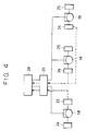
- the upper and lower flange end guide rollers are arranged in pairs, it is usually more expedient to connect the pairs through a connecting shaft so that they can move simultaneously, and to arrange a clutch or a gear coupling in the middle of the connecting shaft so as to compensate for any fluctuation in level due to a difference in the wear of the rollers.
- the flange end guide rollers 18a can be moved up and down independently of the web guides 2a so that the distance between the roller surfaces of the flange end guide rollers 18a and the guide surface of the web guide 2a can be individually adjusted, whereby the flange end surfaces are roller-constrained so as to keep the distance between the web and web guides constantly at an appropriate value even when there is a change in H-beam dimension, such as flange depth, or when a dimensional fluctuation occurs as a result of the flange end guide rollers and the web guides being worn.
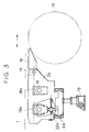
- a scraper 16 (Fig. 3), which is provided, in particular, at the front end of the web guide 2a through a pivot pin 15, can be kept substantially horizontal, though there may be some variation in the degree of horizontality depending on the diameter of the horizontal rolls 17 of the universal mill.
- a high level of guiding precision is obtained in close vicinity of the horizontal rolls of the universal mill, thereby effectively reducing defects such as warping and advantageously restraining web off-centering at the front and rear ends of the H-beam.
- Fig. 5 includes flange end guide rollers 18a, web guides 2a and flange-outer-surface guide rollers 30a having a function of guiding the flange outer surfaces.
- the flange-outer-surface guide rollers 30a are rotatably mounted on a frame 31a attached to the support base 3a, through axles 32a. Their positioning with respect to the outer flange surfaces is effected by means of cylinders 33a.
- the guides for guiding the material to be rolled can be appropriately positioned on-line for each pass even in a case where shapes of different flange depths are to be rolled in the same rolling line, thus making it possible to obtain shapes having a high level of dimensional precision.
Landscapes
- Engineering & Computer Science (AREA)
- Mechanical Engineering (AREA)
- Metal Rolling (AREA)
- Reduction Rolling/Reduction Stand/Operation Of Reduction Machine (AREA)
- Registering, Tensioning, Guiding Webs, And Rollers Therefor (AREA)
Applications Claiming Priority (6)
| Application Number | Priority Date | Filing Date | Title |
|---|---|---|---|
| JP408520/90 | 1990-12-27 | ||
| JP2408520A JPH04228216A (ja) | 1990-12-27 | 1990-12-27 | H形鋼用ウエブガイド装置 |
| JP203691/91 | 1991-07-19 | ||
| JP3203691A JP2610728B2 (ja) | 1991-07-19 | 1991-07-19 | 形鋼の圧延用ガイド |
| JP31194091A JP2627693B2 (ja) | 1991-10-30 | 1991-10-30 | 形鋼の圧延設備におけるガイド装置 |
| JP311940/91 | 1991-10-30 |
Publications (3)
| Publication Number | Publication Date |
|---|---|
| EP0493775A2 true EP0493775A2 (fr) | 1992-07-08 |
| EP0493775A3 EP0493775A3 (en) | 1992-07-22 |
| EP0493775B1 EP0493775B1 (fr) | 1995-03-22 |
Family
ID=27328270
Family Applications (1)
| Application Number | Title | Priority Date | Filing Date |
|---|---|---|---|
| EP91122114A Expired - Lifetime EP0493775B1 (fr) | 1990-12-27 | 1991-12-23 | Dispositif de guidage pour le laminage de profilés |
Country Status (4)
| Country | Link |
|---|---|
| US (1) | US5195347A (fr) |
| EP (1) | EP0493775B1 (fr) |
| KR (1) | KR940002748B1 (fr) |
| DE (1) | DE69108373T2 (fr) |
Cited By (3)
| Publication number | Priority date | Publication date | Assignee | Title |
|---|---|---|---|---|
| CN109500101A (zh) * | 2018-12-24 | 2019-03-22 | 中冶南方工程技术有限公司 | 一种侧导装置 |
| CN110976527A (zh) * | 2019-11-19 | 2020-04-10 | 天津天重中直科技工程有限公司 | 一种新型的轧机前对中装置 |
| CN115069793A (zh) * | 2022-06-27 | 2022-09-20 | 山东钢铁股份有限公司 | 一种热轧单齿履带板防咬偏装置 |
Families Citing this family (9)
| Publication number | Priority date | Publication date | Assignee | Title |
|---|---|---|---|---|
| DE10329525B4 (de) * | 2003-06-30 | 2006-02-09 | Betriebsforschungsinstitut VDEh - Institut für angewandte Forschung GmbH | Verfahren und Vorrichtung zum Richten eines warmen Profils sowie Verfahren zum Herstellen eines normgerechten Profils |
| KR101129983B1 (ko) * | 2009-03-19 | 2012-03-27 | 현대제철 주식회사 | 교정기용 형강 이송 가이드 롤 장치 |
| GB201106138D0 (en) | 2011-04-12 | 2011-05-25 | Siemens Vai Metals Tech Ltd | Feed roll assembly |
| CN104550270A (zh) * | 2014-12-24 | 2015-04-29 | 山东钢铁股份有限公司 | 热轧叉车门架槽钢出口滚动导卫装置 |
| CN109576570B (zh) * | 2018-11-15 | 2020-11-24 | 包头钢铁(集团)有限责任公司 | 一种大断面含硼低屈强比355MPa热轧H型钢及其生产方法 |
| DE102023127684A1 (de) | 2023-08-23 | 2025-02-27 | Sms Group Gmbh | Profilwalzwerk und Verfahren zum Walzen von Walzgut in einem Profilwalzwerk |
| EP4599952A2 (fr) | 2023-08-23 | 2025-08-13 | SMS Group GmbH | Laminoir à profilés et procédé de laminage de produits à laminer dans un laminoir à profilés |
| CN117139389A (zh) * | 2023-09-05 | 2023-12-01 | 齐鲁工业大学(山东省科学院) | 一种tc4钛合金板材表层高熵合金改性实验设备 |
| DE102023127683A1 (de) | 2023-10-10 | 2025-04-10 | Sms Group Gmbh | Profilwalzwerk sowie Verfahren zum Betrieb eines Profilwalzwerks |
Family Cites Families (11)
| Publication number | Priority date | Publication date | Assignee | Title |
|---|---|---|---|---|
| US3566656A (en) * | 1967-10-16 | 1971-03-02 | Kawasaki Steel Co | Device for shaping edges of shape steel |
| JPS56126001A (en) * | 1980-03-06 | 1981-10-02 | Kawasaki Steel Corp | Preventing apparatus for leaning of flange |
| JPH069704B2 (ja) * | 1985-08-30 | 1994-02-09 | 川崎製鉄株式会社 | H形鋼のウエブガイド装置 |
| JPH0659497B2 (ja) * | 1987-06-24 | 1994-08-10 | 川崎製鉄株式会社 | 粗ユニバ−サル圧延機のガイド |
| JPH0659498B2 (ja) * | 1987-07-13 | 1994-08-10 | 川崎製鉄株式会社 | ガイド装置 |
| JPH0780005B2 (ja) * | 1987-07-29 | 1995-08-30 | 川崎製鉄株式会社 | H形鋼圧延設備のガイド装置 |
| JPH0284713A (ja) * | 1988-02-24 | 1990-03-26 | Hitachi Ltd | 半導体装置の製造方法 |
| JP2788275B2 (ja) * | 1988-06-06 | 1998-08-20 | キヤノン株式会社 | 半導体装置の製造方法 |
| US5031435A (en) * | 1988-06-16 | 1991-07-16 | Kawasaki Steel Corporation | Adjustable width rolls for rolling mill |
| JPH0280113A (ja) * | 1988-09-19 | 1990-03-20 | Nippon Steel Corp | フランジを有する形材圧延用のガイド |
| JPH0653289B2 (ja) * | 1989-04-27 | 1994-07-20 | 川崎製鉄株式会社 | 形鋼の圧延装置 |
-
1991
- 1991-12-19 US US07/811,173 patent/US5195347A/en not_active Expired - Fee Related
- 1991-12-20 KR KR1019910023585A patent/KR940002748B1/ko not_active Expired - Fee Related
- 1991-12-23 EP EP91122114A patent/EP0493775B1/fr not_active Expired - Lifetime
- 1991-12-23 DE DE69108373T patent/DE69108373T2/de not_active Expired - Fee Related
Cited By (4)
| Publication number | Priority date | Publication date | Assignee | Title |
|---|---|---|---|---|
| CN109500101A (zh) * | 2018-12-24 | 2019-03-22 | 中冶南方工程技术有限公司 | 一种侧导装置 |
| CN109500101B (zh) * | 2018-12-24 | 2024-03-22 | 中冶南方工程技术有限公司 | 一种侧导装置 |
| CN110976527A (zh) * | 2019-11-19 | 2020-04-10 | 天津天重中直科技工程有限公司 | 一种新型的轧机前对中装置 |
| CN115069793A (zh) * | 2022-06-27 | 2022-09-20 | 山东钢铁股份有限公司 | 一种热轧单齿履带板防咬偏装置 |
Also Published As
| Publication number | Publication date |
|---|---|
| KR940002748B1 (ko) | 1994-04-02 |
| EP0493775A3 (en) | 1992-07-22 |
| KR920011601A (ko) | 1992-07-24 |
| DE69108373D1 (de) | 1995-04-27 |
| US5195347A (en) | 1993-03-23 |
| EP0493775B1 (fr) | 1995-03-22 |
| DE69108373T2 (de) | 1995-11-23 |
Similar Documents
| Publication | Publication Date | Title |
|---|---|---|
| US5195347A (en) | Guide device for shape rolling | |
| US5970764A (en) | Roll forming apparatus | |
| US3301031A (en) | Roller leveler | |
| CN1010561B (zh) | 轧机机座 | |
| US4406141A (en) | Straightening apparatus for steel pipes and the like | |
| US6282932B1 (en) | Axial and transverse roller die adjustment apparatus and method | |
| US3848447A (en) | Rolling method and a rolling mill for carrying out the method | |
| US3613428A (en) | Rolling mills | |
| US3420082A (en) | Leveler | |
| EP0504495B1 (fr) | Appareil à rouleaux pour le dressage des profilés en forme de H | |
| US3699794A (en) | Universal rolling mill stand having more than one caliber for rolling profiles beams such as i-beams | |
| CA2498303C (fr) | Systeme de flexion avec peu de frottement dans une cage de laminoir a plusieurs cylindres | |
| JP2974527B2 (ja) | H形鋼のフランジ直角度矯正装置および矯正設備列 | |
| JPH0242561B2 (fr) | ||
| JPH035011A (ja) | 形鋼の圧延用ガイド | |
| JP2610728B2 (ja) | 形鋼の圧延用ガイド | |
| RU2101112C1 (ru) | Моталка прокатного стана для холоднокатаной полосы | |
| JP4159456B2 (ja) | 形状制御性及び通板性に優れた板圧延機 | |
| JPH11188407A (ja) | ハウジングレスユニバ−サル圧延機 | |
| JPH04361802A (ja) | クロスミル | |
| GB2063742A (en) | Triplet rolling mills | |
| JPS5831241B2 (ja) | ペア−クロス式4段圧延機 | |
| JPH0659497B2 (ja) | 粗ユニバ−サル圧延機のガイド | |
| RU2019325C1 (ru) | Устройство для обработки кромок ленты | |
| SU935144A1 (ru) | Вертикальна клеть прокатного стана |
Legal Events
| Date | Code | Title | Description |
|---|---|---|---|
| PUAI | Public reference made under article 153(3) epc to a published international application that has entered the european phase |
Free format text: ORIGINAL CODE: 0009012 |
|
| PUAL | Search report despatched |
Free format text: ORIGINAL CODE: 0009013 |
|
| AK | Designated contracting states |
Kind code of ref document: A2 Designated state(s): DE LU |
|
| AK | Designated contracting states |
Kind code of ref document: A3 Designated state(s): DE LU |
|
| 17P | Request for examination filed |
Effective date: 19920820 |
|
| 17Q | First examination report despatched |
Effective date: 19930820 |
|
| GRAA | (expected) grant |
Free format text: ORIGINAL CODE: 0009210 |
|
| AK | Designated contracting states |
Kind code of ref document: B1 Designated state(s): DE LU |
|
| REF | Corresponds to: |
Ref document number: 69108373 Country of ref document: DE Date of ref document: 19950427 |
|
| PLBE | No opposition filed within time limit |
Free format text: ORIGINAL CODE: 0009261 |
|
| STAA | Information on the status of an ep patent application or granted ep patent |
Free format text: STATUS: NO OPPOSITION FILED WITHIN TIME LIMIT |
|
| 26N | No opposition filed | ||
| PGFP | Annual fee paid to national office [announced via postgrant information from national office to epo] |
Ref country code: DE Payment date: 19991230 Year of fee payment: 9 |
|
| PGFP | Annual fee paid to national office [announced via postgrant information from national office to epo] |
Ref country code: LU Payment date: 20000111 Year of fee payment: 9 |
|
| PG25 | Lapsed in a contracting state [announced via postgrant information from national office to epo] |
Ref country code: LU Free format text: LAPSE BECAUSE OF NON-PAYMENT OF DUE FEES Effective date: 20001223 |
|
| PG25 | Lapsed in a contracting state [announced via postgrant information from national office to epo] |
Ref country code: DE Free format text: LAPSE BECAUSE OF NON-PAYMENT OF DUE FEES Effective date: 20011002 |