EP0516465A2 - Elektrischer Verbinder mit Kontakthalterungsmittel - Google Patents
Elektrischer Verbinder mit Kontakthalterungsmittel Download PDFInfo
- Publication number
- EP0516465A2 EP0516465A2 EP92304940A EP92304940A EP0516465A2 EP 0516465 A2 EP0516465 A2 EP 0516465A2 EP 92304940 A EP92304940 A EP 92304940A EP 92304940 A EP92304940 A EP 92304940A EP 0516465 A2 EP0516465 A2 EP 0516465A2
- Authority
- EP
- European Patent Office
- Prior art keywords
- contact
- electrical connector
- retention portion
- sidewalls
- edge
- Prior art date
- Legal status (The legal status is an assumption and is not a legal conclusion. Google has not performed a legal analysis and makes no representation as to the accuracy of the status listed.)
- Withdrawn
Links
- 230000014759 maintenance of location Effects 0.000 title claims abstract description 32
- 230000013011 mating Effects 0.000 claims abstract description 16
- 239000012212 insulator Substances 0.000 claims abstract description 11
- 239000007787 solid Substances 0.000 claims abstract description 10
- 239000000463 material Substances 0.000 claims description 3
- 238000003780 insertion Methods 0.000 abstract description 9
- 230000037431 insertion Effects 0.000 abstract description 9
- 229910000679 solder Inorganic materials 0.000 abstract description 9
- 238000005476 soldering Methods 0.000 abstract description 4
- 238000004519 manufacturing process Methods 0.000 description 5
- 238000013459 approach Methods 0.000 description 3
- 230000000295 complement effect Effects 0.000 description 3
- 238000000034 method Methods 0.000 description 3
- 239000002184 metal Substances 0.000 description 2
- 230000002093 peripheral effect Effects 0.000 description 2
- 229910000906 Bronze Inorganic materials 0.000 description 1
- OAICVXFJPJFONN-UHFFFAOYSA-N Phosphorus Chemical compound [P] OAICVXFJPJFONN-UHFFFAOYSA-N 0.000 description 1
- 239000010974 bronze Substances 0.000 description 1
- KUNSUQLRTQLHQQ-UHFFFAOYSA-N copper tin Chemical compound [Cu].[Sn] KUNSUQLRTQLHQQ-UHFFFAOYSA-N 0.000 description 1
- 210000005069 ears Anatomy 0.000 description 1
- 238000007373 indentation Methods 0.000 description 1
- 210000003127 knee Anatomy 0.000 description 1
- 238000012423 maintenance Methods 0.000 description 1
- 230000010287 polarization Effects 0.000 description 1
- 230000000717 retained effect Effects 0.000 description 1
- 239000012815 thermoplastic material Substances 0.000 description 1
Images


Classifications
-
- H—ELECTRICITY
- H01—ELECTRIC ELEMENTS
- H01R—ELECTRICALLY-CONDUCTIVE CONNECTIONS; STRUCTURAL ASSOCIATIONS OF A PLURALITY OF MUTUALLY-INSULATED ELECTRICAL CONNECTING ELEMENTS; COUPLING DEVICES; CURRENT COLLECTORS
- H01R13/00—Details of coupling devices of the kinds covered by groups H01R12/70 or H01R24/00 - H01R33/00
- H01R13/40—Securing contact members in or to a base or case; Insulating of contact members
- H01R13/405—Securing in non-demountable manner, e.g. moulding, riveting
- H01R13/41—Securing in non-demountable manner, e.g. moulding, riveting by frictional grip in grommet, panel or base
-
- H—ELECTRICITY
- H01—ELECTRIC ELEMENTS
- H01R—ELECTRICALLY-CONDUCTIVE CONNECTIONS; STRUCTURAL ASSOCIATIONS OF A PLURALITY OF MUTUALLY-INSULATED ELECTRICAL CONNECTING ELEMENTS; COUPLING DEVICES; CURRENT COLLECTORS
- H01R12/00—Structural associations of a plurality of mutually-insulated electrical connecting elements, specially adapted for printed circuits, e.g. printed circuit boards [PCB], flat or ribbon cables, or like generally planar structures, e.g. terminal strips, terminal blocks; Coupling devices specially adapted for printed circuits, flat or ribbon cables, or like generally planar structures; Terminals specially adapted for contact with, or insertion into, printed circuits, flat or ribbon cables, or like generally planar structures
- H01R12/70—Coupling devices
- H01R12/71—Coupling devices for rigid printing circuits or like structures
- H01R12/72—Coupling devices for rigid printing circuits or like structures coupling with the edge of the rigid printed circuits or like structures
- H01R12/722—Coupling devices for rigid printing circuits or like structures coupling with the edge of the rigid printed circuits or like structures coupling devices mounted on the edge of the printed circuits
- H01R12/727—Coupling devices presenting arrays of contacts
-
- H—ELECTRICITY
- H01—ELECTRIC ELEMENTS
- H01R—ELECTRICALLY-CONDUCTIVE CONNECTIONS; STRUCTURAL ASSOCIATIONS OF A PLURALITY OF MUTUALLY-INSULATED ELECTRICAL CONNECTING ELEMENTS; COUPLING DEVICES; CURRENT COLLECTORS
- H01R13/00—Details of coupling devices of the kinds covered by groups H01R12/70 or H01R24/00 - H01R33/00
- H01R13/648—Protective earth or shield arrangements on coupling devices, e.g. anti-static shielding
- H01R13/658—High frequency shielding arrangements, e.g. against EMI [Electro-Magnetic Interference] or EMP [Electro-Magnetic Pulse]
- H01R13/6591—Specific features or arrangements of connection of shield to conductive members
- H01R13/6596—Specific features or arrangements of connection of shield to conductive members the conductive member being a metal grounding panel
Definitions
- the present invention relates to an electrical connector, and more particularly, to a contact alignment and retention system for right-angle electrical connectors.
- Right-angle, D-faced electrical connectors are used in the electronics industry as input/output (I/O) devices to interconnect a computer to external peripheral equipment.
- the contacts of the electrical connector are typically soldered to conductive traces on a printed circuit board at a backwall or panel of the computer.
- the front face of the connector in addition to having the D-face for polarization, is mated with a complementary electrical connector which is attached to the peripheral equipment.
- the electrical contacts are supported in apertures in the insulative housing of the connector with the back ends of the contacts bent at right angles.
- Each contact terminates in solder posts which extend downward from the connector housing for insertion into through-plated holes in a printed circuit board (PCB) for subsequent soldering thereto. Maintaining the position and alignment of the projecting solder posts for ease of insertion into pre-formed plated through holes in a PCB has been recognized as a desirable feature of these connectors.
- PCB printed circuit board
- U.S. Patent 4,491,376 illustrates another approach where the slots in the connector locator plate are formed to be narrower than the solder posts and which slots are configured to have recesses providing detents to retain the solder posts therein.
- Another slotted locator plate technique is shown in U.S. Patent 4,789,346 (Frantz) wherein the locator plate slots are particularly configured to provide deflectable beams therebetween, the particularly configured slots receiving U-shaped portions of the contact therein.
- another approach addressing not only the maintenance of the contacts in a horizontal position but also in a vertical position is illustrated in U.S. Patent 4,842,528 (Frantz) wherein the U-shaped retention portion of the solder posts are particularly configured to have stop shoulders to engage the top or bottom surfaces, or both such surfaces of the locator plate in an effort to prevent vertical movement of the contact in the connector.
- an electrical connector comprises an insulator of insulative material including a body having a front face and a rear face with a plurality of contact receiving apertures extending therethrough.
- the body includes a locator plate having a plurality of slots each of which is defined by a pair of spaced, opposing sidewalls. Each slot opens adjacent the body rear face and extends toward the body front face.
- a plurality of electrical contacts are included, each contact having a mating portion, a retention portion and a terminal portion. Each mating portion is received in a respective body aperture. Each retention portion is received in interference fit in a locator plate slot. Each terminal portion projects outwardly from the locator plate.
- each contact has a solid cross-section and at least one barb having an exterior linear edge disposed obliquely relative to and in engagement with one of the slot sidewalls.
- Such exterior edge extends along the line converging with the sidewall in a direction toward the body rear face.
- an electrical contact for use in an electrical connector.
- the contact comprises a generally elongate conductive member having a mating portion at one end thereof, a terminal portion at the opposite end thereof and a retention portion therebetween.
- the retention portion has a solid cross-section and has a generally flat outside surface and a pair of spaced exterior edges each of which intersects the outside surface obliquely. Each such edge defines a respective barb for retentive engagement of the contact in an electrical connector.
- Figure 1 is a rear perspective view of an electrical connector in accordance with a preferred form of the invention, partially broken away to reveal two contacts exploded from the connector.
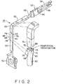
- Figure 2 is a perspective view showing an electrical contact of the subject invention in a stage of manufacture, with an enlarged portion showing details of the cross-section of the contact retention portion.
- Figure 3 is an enlarged view of a portion of the electrical connector of Figure 1 showing details of the electrical contact as retained in a slot in the electrical connector.
- FIG. 1 a right-angle D-faced electrical connector 10 for mounting on a printed circuit board.
- Connector 10 basically comprises an insulator 12 and a plurality of right-angle electrical contacts 14.
- the connector 10 may comprise a conductive shell for protection against electro-magnetic or radio frequency interference (EMI/RFI) and hardware for attaching the connector to a complementary connector and for locking to a printed circuit board.
- EMI/RFI electro-magnetic or radio frequency interference
- Such shell and hardware are not shown in the drawings nor do they form any part of the instant invention.
- the insulator 12 is formed of insulative material, preferably being a molded, one-piece, thermo-plastic material and comprises a generally elongate body 16.
- the body 16 includes a front face 18 and a rear face 20.
- the insulator body 16 comprises a front nose portion 22 configured in the conventional D-shape for polarized connection to a complementary connector, a pair of opposed, spaced endwalls 24 and 26, a top wall 28 and a bottom wall 30. Projecting outwardly from the respective endwalls 24 and 26 are mounting ears 32 and 34.
- Formed through the nose portion 22 are a plurality of apertures 36 which open through the front face 18 of the body 16.
- a cavity 38 opening at the rear face 20 of the body 16 extends between the endwalls 24, 26, the top wall 28 and the bottom wall 30, cavity 38 communicating with the apertures 36.
- apertures 36 are accessible for receipt of the contacts 14 therein through the cavity 38 opening at the rear face of the connector body 16.
- the bottom wall 30 serves as a locator plate for the contacts, as will be described in detail hereinafter, and has therethrough a plurality of slots 40.
- Slots 40 open at the rear face 20 of the body 16, communicate with the cavity 38 and extend toward the body front face 18.
- Each slot 40 in the preferred arrangement, is defined by a pair of spaced, opposing, substantially parallel sidewalls 42.
- Each sidewall has in the preferred form, an inclined surface 44 which together define a wider opening of the slot at the rear face 20 to serve as an entrance guide for insertion of the contacts therein.
- the slots 40 may be formed to alternate between longer and shorter lengths extending toward the front face 18 of the body 16, as shown.
- the electrical contacts basically comprise a mating portion 46 at one end of the contact, a retention portion extending at a right angle with respect to the mating portion 46, and a terminal portion 50 at the other end of the contact 14.
- the mating portion 46 of each contact is received in a respective body aperture 36 and may have serrated edges 52 to provide secured receipt in such apertures 36.
- the contact retention portions 48 of the contacts are received in the slots 40 in the locator plate 30, as will be described, at least two contacts being received in each slot 40.
- the terminal portion 50 of each contact projects downwardly from the locator plate 30 substantially perpendicularly thereto, each portion 50 serving as a solder post for subsequent soldering to plated-through openings in a printed circuit board.
- Contact 14 is comprised of a conductive metal, such as phosphor bronze.
- contact 14 is formed as a one-piece, integral member, stamped and formed from a sheet of such metal.
- contact 14 is of generally elongate structure and formed at a substantially right angle such that the terminal portion 50 extends generally perpendicular to the mating portion 46.
- the terminal portion 50 during manufacture may be attached to a carrier strip 54 which is subsequently severed before the contact 14 is in use.
- the mating portion 46 is shown as a female socket comprising a pair of spaced tines 56, 58 but, may also be a male pin.
- a shank 60 of solid, generally rectangular cross-section Attached to the contact mating portion 46 is a shank 60 of solid, generally rectangular cross-section.
- the mating portion 46 in the preferred arrangement shown, is rotated 90 degrees with respect to shank 60 through a twisted neck portion 62.
- the shank 60 is bent at knee 64 to provide the right angle bend of the terminal portion 50 relative to the mating portion 46.
- the contact retention portion 48 Extending downwardly from the shank 60 is the contact retention portion 48 which, in the preferred embodiment is formed of a solid cross-section of trapezoidal shape.
- the contact comprises a pair of spaced, opposing, substantially parallel, flat outside surfaces 66 and 68.
- Non-parallel, linear exterior edges 70 and 72 intersect obliquely the flat surfaces 66 and 68 and together therewith form the trapezoidal cross-section.
- Edges 70 and 72 are formed to lie in respective directions that converge toward each other and that converge toward the flat surface 66 which faces contact mating portion 46.
- the contact terminal portion 50 is of solid cross-section and, in the preferred form, comprises a generally circular cross-section for enhanced stiffness for insertion into a printed circuit board.
- the curved surfaces of the upper recesses 74 and 76 merge with the curved surfaces of the lower recesses 78 and 80 to define the exterior linear edges 70 and 72, respectively.
- Edges 70 and 72 are each formed to be relatively sharp and serve as a barb to retain the contacts in the locator plate slots as will now be described by further reference to Figure 3.
- the contact retention portion 48 at the location of the barbs 70 and 72 is formed such that the width of the outside surface 68 thereat is of greater dimension than the spacing, s, between the sidewalls 42 defining each slot 40.
- the width of the opposing outside surface 66 at the location of the barbs 70 and 72 is preferably formed to be of dimension less than the spacing, s, between the sidewalls 42 of a respective slot 40.
- linear edges 70 and 72 of the barbs lie obliquely relative to the opposing sidewalls 42 such that each edge 70 and 72 converges with a respective sidewall in a direction toward the rear face of the insulator body.
- the edges 70 and 72 of the barbs engage the sidewalls 42 adjacent the trailing edge 68 of the contact retention portion.
- the width of leading edge 66 is less than the spacing, s, between the sidewalls, the edges 70 and 72 adjacent the leading edge 66 will not engage the sidewalls.
- the edges 70 and 72 will scrape or deform the opposing sidewalls 42 causing an indentation 82, as illustrated in Figure 3, in the respective sidewalls 42.
- an indentation 82 as illustrated in Figure 3, in the respective sidewalls 42.
- a biting engagement of the barbs sharp edges 70 and 72 is achieved.
- Such a biting arrangement into the locator plate slots maintains the contact 14 in intimate retention with the slot sidewalls thereby providing resistance to horizontal motion in the X, Y plane, and to vertical motion in the Z plane.
- manufacture is simplified.
- the locator plate 30 is formed as an integral one-piece structure with the body 16, assembly of the contacts is simplified with the use of fewer parts.
Landscapes
- Coupling Device And Connection With Printed Circuit (AREA)
- Connector Housings Or Holding Contact Members (AREA)
- Multi-Conductor Connections (AREA)
Applications Claiming Priority (2)
| Application Number | Priority Date | Filing Date | Title |
|---|---|---|---|
| US707369 | 1991-05-30 | ||
| US07/707,369 US5112233A (en) | 1991-05-30 | 1991-05-30 | Electrical connector having contact retention means |
Publications (2)
| Publication Number | Publication Date |
|---|---|
| EP0516465A2 true EP0516465A2 (de) | 1992-12-02 |
| EP0516465A3 EP0516465A3 (en) | 1993-06-16 |
Family
ID=24841433
Family Applications (1)
| Application Number | Title | Priority Date | Filing Date |
|---|---|---|---|
| EP19920304940 Withdrawn EP0516465A3 (en) | 1991-05-30 | 1992-05-29 | Electrical connector and contact having retention means |
Country Status (4)
| Country | Link |
|---|---|
| US (1) | US5112233A (de) |
| EP (1) | EP0516465A3 (de) |
| JP (1) | JPH0793164B2 (de) |
| CA (1) | CA2069379C (de) |
Cited By (3)
| Publication number | Priority date | Publication date | Assignee | Title |
|---|---|---|---|---|
| WO1998009353A1 (en) * | 1996-08-30 | 1998-03-05 | The Whitaker Corporation | Board-mountable electrical connector |
| EP0806813A3 (de) * | 1996-05-10 | 1998-12-09 | Molex Incorporated | Elektrischer Steckverbinder mit verbesserten Kontaktstückhaltemitteln |
| EP0810696A3 (de) * | 1996-05-28 | 1999-01-13 | Yazaki Corporation | Leiterplattenverbinder |
Families Citing this family (39)
| Publication number | Priority date | Publication date | Assignee | Title |
|---|---|---|---|---|
| JP2535258Y2 (ja) * | 1991-04-30 | 1997-05-07 | 日本航空電子工業株式会社 | コネクタの係止構造 |
| US5286221A (en) * | 1992-10-19 | 1994-02-15 | Molex Incorporated | Filtered electrical connector assembly |
| US5358413A (en) * | 1992-12-08 | 1994-10-25 | The Whitaker Corporation | Right-angle board-mountable electrical connector with precision terminal positioning |
| US5340320A (en) * | 1993-06-25 | 1994-08-23 | The Whitaker Corporation | Shield for a header having right angle electrical terminals |
| US5403215A (en) * | 1993-12-21 | 1995-04-04 | The Whitaker Corporation | Electrical connector with improved contact retention |
| DE9415079U1 (de) * | 1994-09-16 | 1994-11-17 | Siemens AG, 80333 München | Einpreß-Federleiste |
| JPH08124638A (ja) * | 1994-10-20 | 1996-05-17 | Amp Japan Ltd | 表面実装型コネクタ及びその電気コンタクト |
| US5584709A (en) * | 1995-01-30 | 1996-12-17 | Molex Incorporated | Printed circuit board mounted electrical connector |
| CA2173067A1 (en) * | 1995-03-30 | 1996-10-01 | Mark G. Hopson | Electrical connector having improved contact retention means |
| US5688129A (en) * | 1995-11-21 | 1997-11-18 | Flaherty; Roger J. | Electrical connector with lead positioning comb |
| US5953815A (en) * | 1995-12-22 | 1999-09-21 | Volex Inc. | Method for making an electrical connection |
| US5692928A (en) * | 1996-05-10 | 1997-12-02 | Molex Incorporated | Electrical connector having terminals with improved retention means |
| GB2335095B (en) * | 1996-12-20 | 2001-08-01 | Whitaker Corp | Electrical connector and method of assembling same |
| JPH10289769A (ja) * | 1997-04-11 | 1998-10-27 | Nec Corp | 電気コネクタ |
| JP3681044B2 (ja) * | 1999-06-02 | 2005-08-10 | 矢崎総業株式会社 | 基板用コネクタ |
| JP3621306B2 (ja) * | 1999-09-16 | 2005-02-16 | ヒロセ電機株式会社 | 電気コネクタ組立体及びそのための電気コネクタ |
| US6773272B2 (en) * | 2002-04-22 | 2004-08-10 | Molex Incorporated | Electrical connector assembly and module incorporating the same |
| US6790102B2 (en) * | 2002-10-10 | 2004-09-14 | Delphi Technologies, Inc. | Twisted flat electrical terminal |
| USD501828S1 (en) * | 2002-12-13 | 2005-02-15 | Hon Hai Precision Ind. Co., Ltd. | Electrical connector assembly |
| USD501650S1 (en) * | 2002-12-20 | 2005-02-08 | Hon Hai Precision Ind. Co., Ltd. | Electrical connector assembly |
| US6743059B1 (en) | 2003-06-23 | 2004-06-01 | Hon Hai Precision Ind. Co., Ltd. | Electrical connector with improved contact retention |
| US7371131B2 (en) * | 2005-04-04 | 2008-05-13 | Fci Americas Technology, Inc. | Connector having retentive rib |
| DE102006036917A1 (de) * | 2006-08-04 | 2008-02-14 | Erni Electronics Gmbh | Mehrpoliger Steckverbinder |
| KR100842544B1 (ko) * | 2006-09-11 | 2008-07-01 | 삼성전자주식회사 | 스케일러블 영상 코딩을 이용한 전송 방법 및 이를 이용한이동통신 시스템 |
| JP5179855B2 (ja) * | 2007-12-21 | 2013-04-10 | 矢崎総業株式会社 | バスバーブロックの組付構造 |
| JP5179854B2 (ja) * | 2007-12-21 | 2013-04-10 | 矢崎総業株式会社 | 板状端子の組付構造 |
| DE102009028273A1 (de) * | 2009-08-06 | 2011-02-10 | Robert Bosch Gmbh | Kontaktmittel |
| JP5224067B2 (ja) * | 2009-11-11 | 2013-07-03 | 住友電装株式会社 | 基板用端子およびこれを備えた基板用コネクタ |
| JP5654323B2 (ja) * | 2010-11-09 | 2015-01-14 | 矢崎総業株式会社 | L字状板端子と絶縁部材との固定構造 |
| JP2012142152A (ja) | 2010-12-28 | 2012-07-26 | Tyco Electronics Japan Kk | 回路基板組立体、基板装置、回路基板組立体の組み立て方法 |
| JP4924854B1 (ja) | 2011-03-15 | 2012-04-25 | オムロン株式会社 | コンタクト及び金属部品の製造方法 |
| JP6116056B2 (ja) * | 2013-08-07 | 2017-04-19 | 日本航空電子工業株式会社 | コネクタ |
| JP2017533563A (ja) | 2014-11-03 | 2017-11-09 | スリーエム イノベイティブ プロパティズ カンパニー | コネクタ |
| DE202015101799U1 (de) * | 2015-04-13 | 2016-07-14 | Fct Electronic Gmbh | Steckermodul für einen elektrischen Rechtecksteckverbinder und Rechtecksteckverbinder mit einem solchen Steckermodul |
| JP1577459S (de) * | 2016-11-14 | 2017-05-29 | ||
| DE102017125811A1 (de) * | 2017-11-06 | 2019-05-09 | Phoenix Contact Gmbh & Co. Kg | Steckverbinder |
| US10700462B2 (en) | 2018-01-18 | 2020-06-30 | Interplex Industries, Inc. | Connector housing |
| DE102018113432A1 (de) * | 2018-06-06 | 2019-12-12 | Samytronic UG | Stiftleiste zur Montage an einer Leiterplatte |
| JP7502097B2 (ja) * | 2020-06-24 | 2024-06-18 | ホシデン株式会社 | 端子対 |
Family Cites Families (17)
| Publication number | Priority date | Publication date | Assignee | Title |
|---|---|---|---|---|
| US2597262A (en) * | 1948-05-01 | 1952-05-20 | Albert J Roger | Electrical connection plug |
| US3493916A (en) * | 1967-07-24 | 1970-02-03 | Molex Products Co | Printed circuit board terminal and connector |
| US3533054A (en) * | 1968-01-11 | 1970-10-06 | United Carr Inc | Electrical terminal structure |
| US3551877A (en) * | 1968-11-20 | 1970-12-29 | Hugh H Eby Co | Electrical connector |
| US4210376A (en) * | 1978-12-07 | 1980-07-01 | Amp Incorporated | Electrical connector receptacle |
| US4292736A (en) * | 1978-09-08 | 1981-10-06 | Amp Incorporated | Method for making jack type receptacles |
| US4186988A (en) * | 1978-09-20 | 1980-02-05 | Amp Incorporated | Electrical connector receptacles |
| US4225209A (en) * | 1979-05-18 | 1980-09-30 | Amp Incorporated | Electrical connector receptacle |
| US4491376A (en) * | 1982-09-20 | 1985-01-01 | General Motors Corporation | Electrical header assembly |
| JPS6087177A (ja) * | 1983-10-18 | 1985-05-16 | 株式会社東芝 | エレベ−タの終端階減速指令装置 |
| JPH0416390Y2 (de) * | 1986-04-30 | 1992-04-13 | ||
| US4697864A (en) * | 1986-06-19 | 1987-10-06 | Amp Incorporated | Printed circuit board receptacle for sealed connector |
| US5004430A (en) * | 1986-11-17 | 1991-04-02 | Amp Incorporated | Panel mount electrical connector |
| DE3644153C2 (de) * | 1986-12-23 | 1994-06-23 | Asea Brown Boveri | Verbinderanordnung für die Herstellung einer elektrischen Leitungsverbindung |
| US4789346A (en) * | 1987-03-27 | 1988-12-06 | Amp Incorporated | Solder post alignment and retention system |
| US4842528A (en) * | 1987-03-27 | 1989-06-27 | Amp Incorporated | Solder post retention means |
| US5037334A (en) * | 1990-11-30 | 1991-08-06 | Amp Corporated | Connector with equal lateral force contact spacer plate |
-
1991
- 1991-05-30 US US07/707,369 patent/US5112233A/en not_active Expired - Lifetime
-
1992
- 1992-05-25 CA CA002069379A patent/CA2069379C/en not_active Expired - Fee Related
- 1992-05-29 EP EP19920304940 patent/EP0516465A3/en not_active Withdrawn
- 1992-06-01 JP JP14056792A patent/JPH0793164B2/ja not_active Expired - Lifetime
Cited By (4)
| Publication number | Priority date | Publication date | Assignee | Title |
|---|---|---|---|---|
| EP0806813A3 (de) * | 1996-05-10 | 1998-12-09 | Molex Incorporated | Elektrischer Steckverbinder mit verbesserten Kontaktstückhaltemitteln |
| CN1098544C (zh) * | 1996-05-10 | 2003-01-08 | 莫列斯公司 | 具有带有改进的保持装置的端子的电气连接器 |
| EP0810696A3 (de) * | 1996-05-28 | 1999-01-13 | Yazaki Corporation | Leiterplattenverbinder |
| WO1998009353A1 (en) * | 1996-08-30 | 1998-03-05 | The Whitaker Corporation | Board-mountable electrical connector |
Also Published As
| Publication number | Publication date |
|---|---|
| CA2069379A1 (en) | 1992-12-01 |
| US5112233A (en) | 1992-05-12 |
| JPH0793164B2 (ja) | 1995-10-09 |
| CA2069379C (en) | 1994-12-06 |
| EP0516465A3 (en) | 1993-06-16 |
| JPH06132047A (ja) | 1994-05-13 |
Similar Documents
| Publication | Publication Date | Title |
|---|---|---|
| US5112233A (en) | Electrical connector having contact retention means | |
| US5192228A (en) | Shielded surface mount electrical connector with integral barbed board lock | |
| EP0635905B1 (de) | Elektrischer Erdungsverbinder | |
| JP4955731B2 (ja) | 基板対基板電気コネクタ組立体 | |
| JP3041676B2 (ja) | 改良された端子保持機構を有する電気コネクタ | |
| JP2724657B2 (ja) | 低プロフィルの電気コネクタ | |
| EP0555963A1 (de) | Stecker mit einteiligem Massestreifen | |
| EP0952632A2 (de) | Elektrischer Verbinder mit eingesetzten Anschlüssen | |
| EP0602443A2 (de) | Vorrichtung für die Befestigung eines Steckverbinders auf einer Leiterplatte | |
| EP0600120A1 (de) | Elektrisches Steckverbindungssystem | |
| EP0795929A2 (de) | Elektrische Verbinderanordnung mit verbessertem Haltemittelcharakteristik | |
| WO1997045896A1 (en) | Surface mountable electrical connector | |
| JPH02295077A (ja) | 表面実装型電気コネクタ | |
| EP0717468B1 (de) | Zuerst Polkontakte zuletzt Erdkontakt unterbrechender Steckverbinder | |
| EP0497554B1 (de) | Befestigungsteil | |
| EP0815621B1 (de) | Zusammenbau einer elektrischenanschlussbuchse und federkontakt dafür | |
| WO1998048485A1 (en) | Shields for electrical connector mated pair | |
| US5306177A (en) | Insulation displacement termination system for input-output electrical connector | |
| US4474418A (en) | Electrical connector assembly | |
| US6074230A (en) | Hermaphroditic electrical connectors | |
| CN114079204A (zh) | 连接器 | |
| US6293825B1 (en) | Electrical connector | |
| US6986671B2 (en) | Board mounted electrical connector assembly | |
| EP0798809A2 (de) | Verriegelungsmechanismus für einen Verbinder für eine biegsame gedruckte Schaltung | |
| US6146172A (en) | Electrical connector |
Legal Events
| Date | Code | Title | Description |
|---|---|---|---|
| PUAI | Public reference made under article 153(3) epc to a published international application that has entered the european phase |
Free format text: ORIGINAL CODE: 0009012 |
|
| AK | Designated contracting states |
Kind code of ref document: A2 Designated state(s): BE CH DE ES FR GB IT LI LU NL SE |
|
| PUAL | Search report despatched |
Free format text: ORIGINAL CODE: 0009013 |
|
| AK | Designated contracting states |
Kind code of ref document: A3 Designated state(s): BE CH DE ES FR GB IT LI LU NL SE |
|
| 17P | Request for examination filed |
Effective date: 19931208 |
|
| RAP3 | Party data changed (applicant data changed or rights of an application transferred) |
Owner name: THOMAS & BETTS CORPORATION |
|
| 17Q | First examination report despatched |
Effective date: 19940905 |
|
| STAA | Information on the status of an ep patent application or granted ep patent |
Free format text: STATUS: THE APPLICATION IS DEEMED TO BE WITHDRAWN |
|
| 18D | Application deemed to be withdrawn |
Effective date: 19950316 |