EP0517259A2 - Schwingungssteuerungsgerät - Google Patents
Schwingungssteuerungsgerät Download PDFInfo
- Publication number
- EP0517259A2 EP0517259A2 EP92109569A EP92109569A EP0517259A2 EP 0517259 A2 EP0517259 A2 EP 0517259A2 EP 92109569 A EP92109569 A EP 92109569A EP 92109569 A EP92109569 A EP 92109569A EP 0517259 A2 EP0517259 A2 EP 0517259A2
- Authority
- EP
- European Patent Office
- Prior art keywords
- control apparatus
- vibration control
- impedance element
- output
- vibration
- Prior art date
- Legal status (The legal status is an assumption and is not a legal conclusion. Google has not performed a legal analysis and makes no representation as to the accuracy of the status listed.)
- Granted
Links
Images


Classifications
-
- G—PHYSICS
- G01—MEASURING; TESTING
- G01C—MEASURING DISTANCES, LEVELS OR BEARINGS; SURVEYING; NAVIGATION; GYROSCOPIC INSTRUMENTS; PHOTOGRAMMETRY OR VIDEOGRAMMETRY
- G01C19/00—Gyroscopes; Turn-sensitive devices using vibrating masses; Turn-sensitive devices without moving masses; Measuring angular rate using gyroscopic effects
- G01C19/56—Turn-sensitive devices using vibrating masses, e.g. vibratory angular rate sensors based on Coriolis forces
- G01C19/5642—Turn-sensitive devices using vibrating masses, e.g. vibratory angular rate sensors based on Coriolis forces using vibrating bars or beams
- G01C19/5649—Signal processing
Definitions
- the present invention relates to a vibration control apparatus, for use, for example, in a vibration gyroscope.
- the invention relates to a vibration control apparatus that offers a constantly stabilized self-induced vibration in a vibrator element that is excited using a piezoelectric element.
- the functions of drive, feedback and detection are performed in a vibration gyro using only one or only a single pair of piezoelectric elements.
- FIG. 1 A prior art vibration control apparatus using two piezoelectric elements is illustrated in FIG 1.
- vibrator 4 comprises drive piezoelectric element 2 and feedback piezoelectric element 3 which are both adhered onto one surface of vibration member 1.
- the output of drive apparatus 5 is supplied directly to drive piezoelectric element 2 while the output of feedback piezoelectric element 3 is fed back directly to drive apparatus 5 so as to form a vibration control apparatus that provides a constantly stabilized self-induced vibration to vibrator 4.
- the vibration gyro shown in FIG 2 comprises drive piezoelectric element 8 adhered to a first surface of vibration member 1 that is rectangular in cross-section, with feedback piezoelectric element 9 adhered to the surface opposite the first surface.
- the detector piezoelectric elements 10 and 11 are adhered to two more surfaces at right angles to the others to make vibrator 4.
- vibrator 4 gives a prescribed self-induced vibration in the direction of axis X in an orthogonal three-dimensional coordinate system.
- FIG 3 An alternative prior art vibration gyro is illustrated in FIG 3.
- the vibration gyro shown in FIG 3 includes vibrator 4 for self-induced vibration in the X axis direction. This vibration is driven by the drive piezoelectric elements 15 and 16 which are adhered respectively to two surfaces of vibration member 1 that is triangular in cross-section.
- the feedback piezoelectric element 17 is adhered to another surface.
- the output from feedback piezoelectric element 17 is fed to drive apparatus 5.
- the feedback piezoelectric element 17 controls the output from drive apparatus 5 to drive piezoelectric elements 15 and 16 respectively via resistances 18 and 19.
- the drive piezoelectric elements 15 and 16 also serve as detection piezoelectric elements.
- the voltages formed by the piezoelectric elements 15 and 16 are differentially amplified by the differential amplifier 12.
- the output of the differential amplifier 12 is processed by the synchronous detector 13 and amplified by the D.C. amplifier 14. At the output of the amplifier 14, it is possible to detect the Coriolis force in the Y axis direction generated by vibrator 4 being rotated around axis Z, that is, to detect the angular velocity.
- the respective piezoelectric elements 8, 9, 10 and 11 are all adhered to vibration member 1 by epoxy resin or other adhesives, creating problems in lack of stability in the self-induced vibration of vibrator 4 because of variations in vibration conditions caused by changes in the strength, elasticity and other properties of the adhesives brought about by changes, for example, in ambient temperature. Such problems may also result from the characteristic differences between drive piezoelectric element 8 and feedback piezoelectric element 9. There are also problems of variations in adhesive properties over time that cause hysteresis in drive conditions, and problems originating from variations in adhesive strength of the detection piezoelectric elements 10 and 11.
- drive piezoelectric elements 15 and 16 are also used as detection piezoelectric elements, making it possible to decrease the changes in offset voltage brought about by changes in the adhesive under the prior technology shown in FIG 2.
- feedback piezoelectric element 17 is still furnished separately in the same manner as in FIG 2.
- the present invention is directed to a vibration control apparatus.
- the vibration control apparatus comprises a vibration member having a surface with a resonance point.
- a piezoelectric element is attached to the surface of the vibration member with the resonance point.
- a drive apparatus is connected via an impedance element to the piezoelectric element to drive the piezoelectric element with an AC drive voltage.
- a feedback circuit is connected between the piezoelectric element and the drive apparatus to control the drive apparatus.
- the feedback circuit includes, for example, a differential amplifier, for differentiating between the output voltage of the impedance element (or equivalently, the voltage obtained at the connection between the piezoelectric element and the impedance element) and an AC reference voltage, which reference voltage is illustratively generated from the drive voltage, so as to generate a control voltage for the drive apparatus.
- a differential amplifier for differentiating between the output voltage of the impedance element (or equivalently, the voltage obtained at the connection between the piezoelectric element and the impedance element) and an AC reference voltage, which reference voltage is illustratively generated from the drive voltage, so as to generate a control voltage for the drive apparatus.
- the piezoelectric element produces strain when stress is applied to it.
- the piezoelectric effect produces an electric displacement that is proportional to the stress.
- an electric field is applied thereto, an electric displacement is produced and an inverse piezoelectric effect produces a strain that is proportional to the electric field.
- the feedback circuit serves to separate out the voltage related to the strain of the piezoelectric member and returns this voltage to the drive apparatus to control the drive apparatus.
- the dual functions of drive and feedback are provided using a single piezoelectric element adhered to one surface of the vibration member.
- the single piezoelectric element causes strain and thus vibration in the vibrator by means of the piezoelectric effect of the piezoelectric element.
- the voltage produced by the inverse piezoelectric effect of the piezoelectric element is separated from the combined voltage present at the connection between the piezoelectric element and the impedance element by the feedback circuit. Because of this, the inventive apparatus is capable of making it easier to assemble the vibrator as compared to the case when a plurality of piezoelectric elements are adhered to the vibration member.
- the inventive apparatus also makes it possible to carry out stabilized self-induced vibration in the vibrator by efficiently removing the effects of differences in characteristics between piezoelectric elements and effects such as physical changes in the adhesive layers.
- the vibration control apparatus may be incorporated in a vibration gyro.
- the vibration gyro of this invention comprises a single piezoelectric element which is adhered to one surface of a vibration member that is polygon-shaped in cross-section.
- a vibrator is formed by splitting at least the electrode of the piezoelectric element (and possibly also the piezoelectric element itself) into first and second parts in the direction of vibration member width.
- Each split electrode of the vibrator is connected with a single drive apparatus via corresponding impedance elements.
- a feedback circuit connects the split electrodes back to the drive apparatus.
- the feedback circuit comprises, for example
- the three functions of drive, feedback and detection are performed by a single piezoelectric element by means of separating and removing the voltages created by the strains in each direction of the piezoelectric element.
- the vibration gyro of the present invention can decrease the effects of adhesives on drive conditions, can control hysteresis in drive conditions even when there are temperature cycles present, and can suppress changes in offset voltage to satisfactorily small amounts. Further, the vibration gyro of the present invention can make vibrator assembly work very quick and easy because only a single piezoelectric element is adhered.
- the vibration gyro of the present invention comprises a first piezoelectric element adhered to a first surface of a vibration member that is polygon-shaped in cross-section and a second piezoelectric element adhered to a second surface of the vibration member that is not parallel to the first surface.
- a drive apparatus is connected to the first and second piezoelectric elements via first and second impedance elements.
- a feedback circuit connects the piezoelectric elements back to the drive apparatus to control the drive apparatus. There are several embodiments for the feedback circuit.
- this embodiment of the vibration gyro of the present invention can decrease the effects that the adhesive has on vibration conditions and drive conditions, can impart stable self-induced vibration to the vibration member, can suppress hysteresis in drive conditions even when temperature cycles are present, and can suppress changes in offset voltage to sufficiently small amounts. Further, the vibration gyro or the present invention makes it possible to perform the work of assembling the vibrator very quickly and easily because it adheres only one pair of piezoelectric elements to the vibration member.
- FIG 1 illustrates a prior art vibration control apparatus.
- FIG 2 and FIG 3 illustrates prior art gyros.
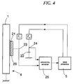
- FIG 4 illustrates a vibration control apparatus in accordance with the preset invention.
- FIG 5, FIG 6, FIG 7, FIG 8, FIG 9 and FIG 10 illustrate gyros in accordance with the present invention.
- FIG 4 is a block diagram that shows an example of this invention, wherein parts that are identical with parts already discussed for prior technology are given the same numbers.
- vibrator 4 is constructed by adhering a single piezoelectric element 20 to one surface of vibration member 4 having a resonance point by means of adhesive layer 21.
- Drive apparatus 5 is attached to this piezoelectric element 20 by means of impedance element Z1 and this drive apparatus 5 is also connected to capacitive element 22 by means of another impedance element Z2, so that the output of drive apparatus 5 can be supplied both to piezoelectric element 20 and to capacitive element 22.
- connection 23 between piezoelectric element 20 and impedance element Z1 and connection 24 between impedance element Z2 and capacitive element 22 are both connected to differential amplifier 25, and this differential amplifier 25 is in turn connected to drive apparatus 5.
- Differential amplifier 25 functions so that it obtains the difference between the outputs from the respective connections 23 and 24 and feeds back the differential output to drive apparatus 5.
- impedance elements Z1 and Z2 may be of any resistance types, capacitive types or induction types, although it is preferred that they each have the same performance, and the capacitance of capacitive element 22 should be identical to that of piezoelectric element 20.
- connection 24 between impedance element Z2 and capacitive element 22 becomes equivalent to the applied alternating current voltage at connection 23 when piezoelectric element 20 is considered as a simple capacitive element, so that the outputs of the two connections 23 and 24 are subtracted at differential amplifier 25 to separate out the voltage produced by the strain of piezoelectric element 20, consequently making it possible to provide stabilized self-induced vibration to vibrator 4 by feeding back the differential output as a feedback signal to drive apparatus 5.
- this invention it is possible to have a single piezoelectric element function as an piezoelectric element for both drive and for feedback. It is possible to make the work of adhering the piezoelectric element to the vibration member and consequently the work of assembling the vibrator extremely easy. It is possible to remove the effects on self-induced vibration of the different characteristics of a plurality of piezoelectric elements, and it is possible to greatly reduce the effects on self-induced vibration imparted by variations in the physical forms of a plurality of adhesive layers.
- inventive vibrator and associated control apparatus may be incorporated in a gyro.
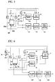
- FIG 5 is a block diagram of an example of a gyro according to the invention, wherein portions that are identical to portions shown for prior technology in the drawings have the same numbers.
- vibrator 4 is constructed by adhering a single piezoelectric element 26 to one surface of the vibration member 1 which has a rectangular shape in cross-section.
- the electrode of this piezoelectric element 26 is split along the width of vibration member 1 to make split electrodes 26a and 26b.
- the entire piezoelectric element 26 can be split instead of just the electrode.
- drive apparatus 5 is connected to split electrodes 26a and 26b via the respective impedance elements Z3 and Z4.
- the drive apparatus is also connected to capacitive element 27 via another impedance element Z5, and these are all capable of receiving alternating current voltage from drive apparatus 5.
- the voltage at the connections 28 and 29 between the split electrodes 26a and 26b and impedance elements Z3 and Z4 are added at adder 30.
- differential amplifier 25 the output from adder 30 and the output from connection 31 between impedance element Z5 and capacitive element 27 are differentially amplified, the result being fed back to drive apparatus 5.
- any of resistance types, capacitive types or induction types as the said several impedance elements Z3, Z4 and Z5.
- the two connections 28 and 29 are connected to differential amplifier 12 and this differential amplifier 12 is connected in succession to synchronous detector 13 and direct current amplifier 14 in the same manner as in prior technology.
- FIG 6 is a block diagram showing another example of a gyro which incorporates a vibration control apparatus of this invention.
- drive apparatus 5 is connected to the respective split electrodes 26a and 26b via the respective impedance elements Z3 and Z4.
- the drive apparatus 5 is also connected to the respective capacitive elements 32 and 33 via the other respective impedance elements Z6 and Z7.
- the respective connections 28 and 29 are connected to adder 34 via the respective differential amplifiers 35 and 36 that differentially amplify with respect to a reference alternating current voltage.
- Differential amplifier 35 differentially amplifies the output of impedance element Z6 from connection 37 and the output impedance element Z3 from connection 28.
- the differential amplifier 36 differentially amplifies the outputs of impedance element Z7 from connection 38 and impedance element Z4 from connection 29.
- adder 34 separates out only the voltage generated by the vibration of vibrator 4 in the X axis direction by means of adding these two differential amplification outputs, so that the detection voltage is fed back to drive apparatus 5 to give stabilized self-induced vibration to vibrator 4.
- the Coriolis force occurring during vibration of vibrator 4 can be separated and detected by inputting the respective outputs of connections 28 and 29 into another differential amplifier 12.
- vibration member 1 with a cross-section in a polygon shape other than rectangular.
- this invention makes it possible to provide stabilized self-induced vibration merely by furnishing a single piezoelectric element on one surface of the vibration member without furnishing a special feedback piezoelectric element, and also makes it possible to detect angular velocity with high precision. That is, by having a single piezoelectric element perform the three functions of drive, feedback and detection, it becomes possible to decrease the effects of adhesive on drive conditions sufficiently, to effectively control formation of hysteresis in drive conditions when, for example, temperature cycles are present. It is also possible to suppress offset voltage changes to a sufficiently small level. As a result it is possible to provide constantly stabilized self-induced vibration while maintaining high detection precision.
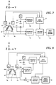
- FIG 7 is a block diagram showing another example of a gyro according to the invention. Those parts that are identical to parts described in the figures for prior technology are shown by identical numbers.
- vibrator 4 is constructed by adhering first piezoelectric element 39 to one surface 1a of vibration member 1 of triangular shape in cross-section while adhering second piezoelectric element 40 to another surface 1b that is adjacent to the surface 1a.
- the respective piezoelectric elements 39 and 40 are connected to drive apparatus 5 via respective impedance elements Z8 and Z9 while drive apparatus 5 is also connected to capacitive element 41 via another impedance elements Z10, so that the alternating current voltage from drive apparatus 5 can be applied simultaneously to piezoelectric elements 39 and 40 and capacitive element 41.
- connections 42 and 43 of the respective piezoelectric elements 39 and 40 and impedance elements Z8 and Z9 are connected to differential amplifier 25 via adder 30.
- the adder 30 adds the outputs from the two connections 42 and 43.
- the output from adder 30 and output from connection 44, which is between impedance element Z10 and capacitive element 41, are differentially amplified and the differential output therefrom is fed back to drive apparatus 5.
- connections 42 and 43 between the respective impedance elements Z8 and Z9 and the respective piezoelectric elements 39 and 40 are connected to differential amplifier 12, and this differential amplifier is connected in succession to synchronous detector 13 and direct current amplifier 14 in the same manner as in prior technology.
- vibrator 4 can be given self-induced vibration in the X axis direction by applying alternating current voltage from drive apparatus 5 respectively to piezoelectric elements 39 and 40.
- the outputs from the respective connections 42 and 43 become a composite output including as components both the supply voltage from drive apparatus 5 and the voltage output from piezoelectric elements 39 and 40 accompanying the strains in the respective piezoelectric elements 39 and 40. Consequently these two combined outputs, after being added at adder 30, pass through differential amplifier 25 so that only the voltage generated from piezoelectric elements 39 and 40 based on vibration in the X axis direction is extracted, and when this is fed back to drive apparatus 5 it is possible to stabilize the self-induced vibration of vibrator 4 sufficiently.
- the device of FIG 8 is a modification of the example shown in FIG 7, where the polarization directions of piezoelectric elements 39a and 40a adhered respectively to side surfaces 1a and 1b of vibration element 1 are the reverse of what is shown in FIG 7, so that the strain and output voltage are mutually reversed between piezoelectric elements 39a and 40a. Consequently, the differential amplification of the respective outputs of connections 42a and 43a through use of the differential amplifier 45 has the same meaning as the adder 30 shown in the example in FIG 7, and the adding of their outputs by the adder 46 has the same meaning as the differential amplification (by differential amplifier 12) in FIG 7.
- connections 42a and 43a between the respective impedance elements Z8 and Z9 and the respective piezoelectric elements 39a and 40a are connected to differential amplifier 45 that differentiates between the outputs from these connections 42a and 43a.
- the differential amplifier 45 is connected to drive apparatus 5 via differential amplifier 25 that differentiates between the output of amplifier 45 and a reference alternating current voltage at the connection 44.
- the two connections 42a and 43a are also connected to synchronous detector 13 via adder 46. Also, each of the drive voltages supplied to the respective piezoelectric elements 39a and 40a have their directional phases reversed by 180 degrees.
- FIG 9 is a block diagram showing another example of this invention.
- This example has drive apparatus 5 connected to the respective piezoelectric elements 39 and 40 via the respective impedance elements Z8 and Z9, while the drive apparatus 5 is also connected to capacitive elements 47 and 48 respectively by other impedance elements Z11 and Z12, and differs from the example shown in FIG 7 in that these respective connections 42 and 43 are connected to adder 34 via respective differential amplifiers 35 and 36.
- the differential amplifiers 35 and 36 differentiate between the voltages at the connections 42 and 43 and first and second reference alternating current voltages.
- differential amplifier 35 differentially amplifies the output from the connection 37 between impedance element Z11 and capacitive element 47 and the output from connection 42
- differential amplifier 36 differentially amplifies the outputs from connection 38 between impedance element Z12 and capacitive element 48 and the output from connection 43.
- adder 34 separates and detects only the voltage generated by the X axis direction vibration of vibrator 4 by means of adding these two differential amplification outputs and feeds the detection voltage back to drive apparatus 5 so that vibrator 4 is given a stabilized self-induced vibration.
- the Coriolis force during rotation of vibrator 4 can be separated and detected by differential amplification after inputting the respective outputs of connections 42 and 43 to another differentiation amplifier 12.
- the present invention furnishes piezoelectric elements on two surfaces of a vibration element that are not mutually parallel and thereby makes it possible to provide stabilized self-induced vibration constantly without furnishing a separate feedback piezoelectric element and also to detect the angular velocity with high precision. That is, by having the three functions of drive, feedback and detection carried out in one pair of piezoelectric elements, it is possible to decrease the effect of the adhesive on drive conditions sufficiently, to suppress effectively the formation of hysteresis in drive conditions when there are, for example, temperature cycles, and to make changes in offset voltage sufficiently small, so that as a result there is a constantly stabilized self-induced vibration while maintaining high precision in detection.
- assembly of the vibrator can be accomplished very quickly and easily because the vibrator can be constructed with only one pair of piezoelectric elements adhered to vibrator 1.
Landscapes
- Engineering & Computer Science (AREA)
- Signal Processing (AREA)
- Physics & Mathematics (AREA)
- General Physics & Mathematics (AREA)
- Radar, Positioning & Navigation (AREA)
- Remote Sensing (AREA)
- Gyroscopes (AREA)
Priority Applications (1)
| Application Number | Priority Date | Filing Date | Title |
|---|---|---|---|
| EP95115256A EP0692698B1 (de) | 1991-06-07 | 1992-06-05 | Schwingungssteuerungsgerät |
Applications Claiming Priority (6)
| Application Number | Priority Date | Filing Date | Title |
|---|---|---|---|
| JP3162330A JP2529786B2 (ja) | 1991-06-07 | 1991-06-07 | 振動ジャイロ |
| JP3162331A JP2583691B2 (ja) | 1991-06-07 | 1991-06-07 | 振動ジャイロ |
| JP162331/91 | 1991-06-07 | ||
| JP3162329A JPH04361112A (ja) | 1991-06-07 | 1991-06-07 | 振動制御装置 |
| JP162329/91 | 1991-06-07 | ||
| JP162330/91 | 1991-06-07 |
Related Child Applications (2)
| Application Number | Title | Priority Date | Filing Date |
|---|---|---|---|
| EP95115256A Division EP0692698B1 (de) | 1991-06-07 | 1992-06-05 | Schwingungssteuerungsgerät |
| EP95115256.0 Division-Into | 1992-06-05 |
Publications (3)
| Publication Number | Publication Date |
|---|---|
| EP0517259A2 true EP0517259A2 (de) | 1992-12-09 |
| EP0517259A3 EP0517259A3 (en) | 1993-03-03 |
| EP0517259B1 EP0517259B1 (de) | 1996-05-15 |
Family
ID=27321985
Family Applications (2)
| Application Number | Title | Priority Date | Filing Date |
|---|---|---|---|
| EP92109569A Expired - Lifetime EP0517259B1 (de) | 1991-06-07 | 1992-06-05 | Schwingungssteuerungsgerät |
| EP95115256A Expired - Lifetime EP0692698B1 (de) | 1991-06-07 | 1992-06-05 | Schwingungssteuerungsgerät |
Family Applications After (1)
| Application Number | Title | Priority Date | Filing Date |
|---|---|---|---|
| EP95115256A Expired - Lifetime EP0692698B1 (de) | 1991-06-07 | 1992-06-05 | Schwingungssteuerungsgerät |
Country Status (3)
| Country | Link |
|---|---|
| US (1) | US5270607A (de) |
| EP (2) | EP0517259B1 (de) |
| DE (2) | DE69225505T2 (de) |
Cited By (7)
| Publication number | Priority date | Publication date | Assignee | Title |
|---|---|---|---|---|
| EP0663584A1 (de) * | 1994-01-14 | 1995-07-19 | Akai Electric Co., Ltd. | Schwingungskontrollanlage für Vibration eines Kreisels |
| EP0702207A1 (de) * | 1994-09-15 | 1996-03-20 | Bei Electronics, Inc. | Proportionaler Messwandler und Verfahren |
| EP0696721A3 (de) * | 1994-08-10 | 1996-04-03 | Akai Electric | Schwingungskontrollanlage mit Regelung der Oszillationsfrequenz |
| EP0929177A3 (de) * | 1998-01-08 | 2000-07-26 | Xerox Corporation | Vorrichtung zur Unterdrückung von Schwingungen |
| WO2008037487A1 (de) * | 2006-09-30 | 2008-04-03 | Deutsches Zentrum für Luft- und Raumfahrt e.V. | Vorrichtung zur reduktion von schwingungen einer struktur |
| DE19828606B4 (de) * | 1997-06-30 | 2011-06-09 | Denso Corporation, Kariya-City | Halbleiter-Giergeschwindigkeitssensor |
| CN103017748A (zh) * | 2012-12-04 | 2013-04-03 | 北京信息科技大学 | 一种钟形振子式角速率陀螺信号提取方法 |
Families Citing this family (31)
| Publication number | Priority date | Publication date | Assignee | Title |
|---|---|---|---|---|
| JPH0674774A (ja) * | 1992-08-27 | 1994-03-18 | Murata Mfg Co Ltd | ジャイロの駆動回路 |
| JP3421720B2 (ja) * | 1992-11-17 | 2003-06-30 | シチズン時計株式会社 | 角速度検出回路 |
| US5525853A (en) * | 1993-01-21 | 1996-06-11 | Trw Inc. | Smart structures for vibration suppression |
| JP3016986B2 (ja) * | 1993-02-17 | 2000-03-06 | 三菱電機株式会社 | 振動ジャイロ用検出回路 |
| JPH0735554A (ja) * | 1993-07-22 | 1995-02-07 | Murata Mfg Co Ltd | 検出回路 |
| JPH07139952A (ja) * | 1993-11-16 | 1995-06-02 | Murata Mfg Co Ltd | 振動ジャイロ |
| JPH08159779A (ja) | 1994-12-02 | 1996-06-21 | Murata Mfg Co Ltd | 振動ジャイロ |
| JP3291968B2 (ja) * | 1994-12-15 | 2002-06-17 | 株式会社村田製作所 | 振動ジャイロ |
| JPH08247770A (ja) * | 1995-03-14 | 1996-09-27 | Murata Mfg Co Ltd | 振動ジャイロ |
| JP2996137B2 (ja) * | 1995-03-31 | 1999-12-27 | 株式会社村田製作所 | 振動ジャイロ |
| JPH08278146A (ja) * | 1995-04-03 | 1996-10-22 | Murata Mfg Co Ltd | 振動ジャイロ |
| JP3000891B2 (ja) * | 1995-06-27 | 2000-01-17 | 株式会社村田製作所 | 振動ジャイロ |
| US5812684A (en) * | 1995-07-05 | 1998-09-22 | Ford Global Technologies, Inc. | Passenger compartment noise attenuation apparatus for use in a motor vehicle |
| US5775715A (en) * | 1995-08-01 | 1998-07-07 | K-2 Corporation | Piezoelectric damper for a board such as a snow ski or snowboard |
| US6095547A (en) * | 1995-08-01 | 2000-08-01 | K-2 Corporation | Active piezoelectric damper for a snow ski or snowboard |
| JPH09105639A (ja) * | 1995-08-08 | 1997-04-22 | Murata Mfg Co Ltd | 振動ジャイロおよびその製造方法 |
| JP2996157B2 (ja) * | 1995-10-12 | 1999-12-27 | 株式会社村田製作所 | 振動ジャイロ |
| JPH09113279A (ja) * | 1995-10-16 | 1997-05-02 | Murata Mfg Co Ltd | 振動ジャイロ |
| US6011345A (en) * | 1996-02-08 | 2000-01-04 | Emf Industries, Inc. | Device and method for controlling transductive systems |
| JPH10232132A (ja) * | 1997-02-20 | 1998-09-02 | Murata Mfg Co Ltd | 振動ジャイロ |
| JPH11247605A (ja) * | 1997-12-26 | 1999-09-14 | United Technol Corp <Utc> | タ―ボマシ―ンコンポ―ネントの振動緩衝方法及び装置 |
| US6193032B1 (en) * | 1998-03-02 | 2001-02-27 | The Penn State Research Foundation | Piezoceramic vibration control device and tuning control thereof |
| JP3425717B2 (ja) | 1999-09-20 | 2003-07-14 | 株式会社村田製作所 | 振動ジャイロ |
| US6617753B1 (en) * | 2002-05-28 | 2003-09-09 | Richard J. Gomulka | Vibratory excitor apparatus and method |
| JP4634707B2 (ja) * | 2002-10-30 | 2011-02-16 | ギブン イメージング リミテッド | 生体内装置、生体内センシング装置、生体内装置の作動方法、および自律型生体内センシング装置の作動方法 |
| US7138747B1 (en) * | 2004-07-29 | 2006-11-21 | Anorad Corporation | Damping and stabilization for linear motor stage |
| DE102005022097A1 (de) * | 2005-05-12 | 2006-11-16 | Fraunhofer-Gesellschaft zur Förderung der angewandten Forschung e.V. | Vorrichtung und Verfahren zur Schwingungstilgung einer mechanischen Struktur |
| JP4967663B2 (ja) * | 2007-01-09 | 2012-07-04 | ソニー株式会社 | 振動型ジャイロセンサ、制御回路及び電子機器 |
| US20080231294A1 (en) * | 2007-03-19 | 2008-09-25 | Ndsu Research Foundation | Structural health monitoring circuit |
| JP5733966B2 (ja) * | 2010-12-10 | 2015-06-10 | キヤノン株式会社 | 振動型駆動装置 |
| DE102020211317A1 (de) | 2020-09-09 | 2022-03-10 | Robert Bosch Gesellschaft mit beschränkter Haftung | Sensorsystem, Verfahren zur Kompensation eines Offsets eines Drehratensignals |
Family Cites Families (19)
| Publication number | Priority date | Publication date | Assignee | Title |
|---|---|---|---|---|
| US3520195A (en) * | 1965-10-11 | 1970-07-14 | Gen Electric | Solid state angular velocity sensing device |
| AU2931571A (en) * | 1970-06-10 | 1972-11-30 | Honeywell Inc | Apparatus for sensing angular rate of movement |
| US3967143A (en) * | 1974-10-10 | 1976-06-29 | Oki Electric Industry Company, Ltd. | Ultrasonic wave generator |
| US4193010A (en) * | 1976-12-09 | 1980-03-11 | Essex Transducers Corporation | Sensor device using piezoelectric coating subjected to bending |
| US4406965A (en) * | 1981-05-12 | 1983-09-27 | The Singer Company | Dither pick-off transducer for ring laser gyroscope |
| US4489609A (en) * | 1981-12-08 | 1984-12-25 | National Research Development Corporation | Gyroscopes |
| JPS61142415A (ja) * | 1984-12-14 | 1986-06-30 | Nippon Denso Co Ltd | 角速度検出装置 |
| US4692649A (en) * | 1985-03-01 | 1987-09-08 | Canon Kabushiki Kaisha | Driving circuit of a vibration wave motor |
| GB2183371B (en) * | 1985-10-09 | 1989-09-27 | Canon Kk | Vibration wave motor and drive circuit therefor |
| US4780062A (en) * | 1985-10-09 | 1988-10-25 | Murata Manufacturing Co., Ltd. | Piezoelectric fan |
| US4709360A (en) * | 1985-11-12 | 1987-11-24 | Sparton Corporation | Hydrophone transducer with negative feedback system |
| US4740726A (en) * | 1986-07-21 | 1988-04-26 | Nohken Inc. | Vibrator-type level sensor |
| US5061882A (en) * | 1987-02-09 | 1991-10-29 | Nikon Corporation | Power supply frequency regulating device for vibration wave driven motor |
| DE3926504C2 (de) * | 1988-08-12 | 1999-11-18 | Murata Manufacturing Co | Schwingkreisel |
| JP2531021B2 (ja) * | 1989-04-06 | 1996-09-04 | 株式会社村田製作所 | 振動子 |
| JPH063455B2 (ja) * | 1989-04-06 | 1994-01-12 | 株式会社村田製作所 | 振動ジャイロ |
| US4879528A (en) * | 1988-08-30 | 1989-11-07 | Olympus Optical Co., Ltd. | Ultrasonic oscillation circuit |
| US5117148A (en) * | 1989-11-07 | 1992-05-26 | Murata Manufacturing Co., Ltd. | Vibrator |
| JPH0571967A (ja) * | 1991-09-17 | 1993-03-23 | Akai Electric Co Ltd | 振動ジヤイロ |
-
1992
- 1992-06-05 DE DE69225505T patent/DE69225505T2/de not_active Expired - Fee Related
- 1992-06-05 EP EP92109569A patent/EP0517259B1/de not_active Expired - Lifetime
- 1992-06-05 DE DE69210679T patent/DE69210679T2/de not_active Expired - Fee Related
- 1992-06-05 EP EP95115256A patent/EP0692698B1/de not_active Expired - Lifetime
- 1992-06-06 US US07/894,017 patent/US5270607A/en not_active Expired - Lifetime
Cited By (9)
| Publication number | Priority date | Publication date | Assignee | Title |
|---|---|---|---|---|
| EP0663584A1 (de) * | 1994-01-14 | 1995-07-19 | Akai Electric Co., Ltd. | Schwingungskontrollanlage für Vibration eines Kreisels |
| US5581142A (en) * | 1994-01-14 | 1996-12-03 | Akai Electric Co., Ltd. | Vibration control device for safely induced vibration of gyroscopes |
| EP0696721A3 (de) * | 1994-08-10 | 1996-04-03 | Akai Electric | Schwingungskontrollanlage mit Regelung der Oszillationsfrequenz |
| US5594168A (en) * | 1994-08-10 | 1997-01-14 | Akai Electric Co. | Vibration control apparatus having oscillation frequency regulation |
| EP0702207A1 (de) * | 1994-09-15 | 1996-03-20 | Bei Electronics, Inc. | Proportionaler Messwandler und Verfahren |
| DE19828606B4 (de) * | 1997-06-30 | 2011-06-09 | Denso Corporation, Kariya-City | Halbleiter-Giergeschwindigkeitssensor |
| EP0929177A3 (de) * | 1998-01-08 | 2000-07-26 | Xerox Corporation | Vorrichtung zur Unterdrückung von Schwingungen |
| WO2008037487A1 (de) * | 2006-09-30 | 2008-04-03 | Deutsches Zentrum für Luft- und Raumfahrt e.V. | Vorrichtung zur reduktion von schwingungen einer struktur |
| CN103017748A (zh) * | 2012-12-04 | 2013-04-03 | 北京信息科技大学 | 一种钟形振子式角速率陀螺信号提取方法 |
Also Published As
| Publication number | Publication date |
|---|---|
| EP0517259B1 (de) | 1996-05-15 |
| DE69210679T2 (de) | 1996-09-26 |
| EP0517259A3 (en) | 1993-03-03 |
| DE69225505D1 (de) | 1998-06-18 |
| DE69210679D1 (de) | 1996-06-20 |
| DE69225505T2 (de) | 1998-09-10 |
| EP0692698A1 (de) | 1996-01-17 |
| EP0692698B1 (de) | 1998-05-13 |
| US5270607A (en) | 1993-12-14 |
Similar Documents
| Publication | Publication Date | Title |
|---|---|---|
| US5270607A (en) | Vibration control apparatus | |
| US7886597B2 (en) | Dynamic amount sensor | |
| US6445195B1 (en) | Drive feedthrough nulling system | |
| US20080148847A1 (en) | Vibration gyro sensor | |
| EP0860685A3 (de) | Vibrationskreisel | |
| US6230562B1 (en) | Detection circuit for vibratory gyro and vibratory gyro device using the same | |
| JP3664950B2 (ja) | 角速度センサ | |
| JP2004279101A (ja) | 振動型角速度センサ | |
| US6477897B1 (en) | Vibrating gyroscope | |
| JP2529786B2 (ja) | 振動ジャイロ | |
| JP2583691B2 (ja) | 振動ジャイロ | |
| JP3265840B2 (ja) | 圧電振動子の駆動検出回路 | |
| JPH05113335A (ja) | 振動ジヤイロ | |
| JP2571893B2 (ja) | 振動ジャイロ | |
| JPH05133754A (ja) | 振動ジヤイロ | |
| JP2686209B2 (ja) | 振動ジャイロ | |
| JPH05126585A (ja) | 振動ジヤイロ | |
| JPH05118853A (ja) | 振動ジヤイロ | |
| JPH07174566A (ja) | 圧電振動ジャイロ用駆動検出器およびこれを用いた圧電振動ジャイロ | |
| JP3149712B2 (ja) | 振動ジャイロ | |
| JPH05306935A (ja) | 圧電振動ジャイロ | |
| JPH06117861A (ja) | 振動ジャイロ | |
| JP2583704B2 (ja) | 発振回路 | |
| JPH0618268A (ja) | 振動ジャイロ用振動子 | |
| JPH109872A (ja) | 角速度センサ |
Legal Events
| Date | Code | Title | Description |
|---|---|---|---|
| PUAI | Public reference made under article 153(3) epc to a published international application that has entered the european phase |
Free format text: ORIGINAL CODE: 0009012 |
|
| AK | Designated contracting states |
Kind code of ref document: A2 Designated state(s): DE FR GB IT NL SE |
|
| PUAL | Search report despatched |
Free format text: ORIGINAL CODE: 0009013 |
|
| AK | Designated contracting states |
Kind code of ref document: A3 Designated state(s): DE FR GB IT NL SE |
|
| 17P | Request for examination filed |
Effective date: 19930730 |
|
| 17Q | First examination report despatched |
Effective date: 19941010 |
|
| GRAH | Despatch of communication of intention to grant a patent |
Free format text: ORIGINAL CODE: EPIDOS IGRA |
|
| GRAA | (expected) grant |
Free format text: ORIGINAL CODE: 0009210 |
|
| AK | Designated contracting states |
Kind code of ref document: B1 Designated state(s): DE FR GB IT NL SE |
|
| XX | Miscellaneous (additional remarks) |
Free format text: TEILANMELDUNG 95115256.0 EINGEREICHT AM 27/09/95. |
|
| ITF | It: translation for a ep patent filed | ||
| REF | Corresponds to: |
Ref document number: 69210679 Country of ref document: DE Date of ref document: 19960620 |
|
| ET | Fr: translation filed | ||
| PLBE | No opposition filed within time limit |
Free format text: ORIGINAL CODE: 0009261 |
|
| STAA | Information on the status of an ep patent application or granted ep patent |
Free format text: STATUS: NO OPPOSITION FILED WITHIN TIME LIMIT |
|
| 26N | No opposition filed | ||
| NLS | Nl: assignments of ep-patents |
Owner name: MITSUBISHI ELECTRIC CORPORATION |
|
| REG | Reference to a national code |
Ref country code: FR Ref legal event code: TP |
|
| REG | Reference to a national code |
Ref country code: GB Ref legal event code: 732E |
|
| REG | Reference to a national code |
Ref country code: GB Ref legal event code: IF02 |
|
| PGFP | Annual fee paid to national office [announced via postgrant information from national office to epo] |
Ref country code: DE Payment date: 20070531 Year of fee payment: 16 |
|
| PGFP | Annual fee paid to national office [announced via postgrant information from national office to epo] |
Ref country code: SE Payment date: 20070607 Year of fee payment: 16 |
|
| PGFP | Annual fee paid to national office [announced via postgrant information from national office to epo] |
Ref country code: NL Payment date: 20070617 Year of fee payment: 16 |
|
| PGFP | Annual fee paid to national office [announced via postgrant information from national office to epo] |
Ref country code: GB Payment date: 20070530 Year of fee payment: 16 |
|
| PGFP | Annual fee paid to national office [announced via postgrant information from national office to epo] |
Ref country code: IT Payment date: 20070622 Year of fee payment: 16 |
|
| PGFP | Annual fee paid to national office [announced via postgrant information from national office to epo] |
Ref country code: FR Payment date: 20070608 Year of fee payment: 16 |
|
| EUG | Se: european patent has lapsed | ||
| GBPC | Gb: european patent ceased through non-payment of renewal fee |
Effective date: 20080605 |
|
| NLV4 | Nl: lapsed or anulled due to non-payment of the annual fee |
Effective date: 20090101 |
|
| REG | Reference to a national code |
Ref country code: FR Ref legal event code: ST Effective date: 20090228 |
|
| PG25 | Lapsed in a contracting state [announced via postgrant information from national office to epo] |
Ref country code: DE Free format text: LAPSE BECAUSE OF NON-PAYMENT OF DUE FEES Effective date: 20090101 |
|
| PG25 | Lapsed in a contracting state [announced via postgrant information from national office to epo] |
Ref country code: NL Free format text: LAPSE BECAUSE OF NON-PAYMENT OF DUE FEES Effective date: 20090101 |
|
| PG25 | Lapsed in a contracting state [announced via postgrant information from national office to epo] |
Ref country code: GB Free format text: LAPSE BECAUSE OF NON-PAYMENT OF DUE FEES Effective date: 20080605 |
|
| PG25 | Lapsed in a contracting state [announced via postgrant information from national office to epo] |
Ref country code: FR Free format text: LAPSE BECAUSE OF NON-PAYMENT OF DUE FEES Effective date: 20080630 Ref country code: IT Free format text: LAPSE BECAUSE OF NON-PAYMENT OF DUE FEES Effective date: 20080605 |
|
| PG25 | Lapsed in a contracting state [announced via postgrant information from national office to epo] |
Ref country code: SE Free format text: LAPSE BECAUSE OF NON-PAYMENT OF DUE FEES Effective date: 20080606 |