EP0523739A1 - Dynamische Drucklagervorrichtung - Google Patents
Dynamische Drucklagervorrichtung Download PDFInfo
- Publication number
- EP0523739A1 EP0523739A1 EP92112281A EP92112281A EP0523739A1 EP 0523739 A1 EP0523739 A1 EP 0523739A1 EP 92112281 A EP92112281 A EP 92112281A EP 92112281 A EP92112281 A EP 92112281A EP 0523739 A1 EP0523739 A1 EP 0523739A1
- Authority
- EP
- European Patent Office
- Prior art keywords
- dynamic pressure
- shaft
- bearing
- grooves
- sliding surface
- Prior art date
- Legal status (The legal status is an assumption and is not a legal conclusion. Google has not performed a legal analysis and makes no representation as to the accuracy of the status listed.)
- Granted
Links
- 239000012530 fluid Substances 0.000 claims abstract description 22
- 238000007789 sealing Methods 0.000 description 3
- 230000001050 lubricating effect Effects 0.000 description 2
- 238000012986 modification Methods 0.000 description 1
- 230000004048 modification Effects 0.000 description 1
Images
Classifications
-
- F—MECHANICAL ENGINEERING; LIGHTING; HEATING; WEAPONS; BLASTING
- F16—ENGINEERING ELEMENTS AND UNITS; GENERAL MEASURES FOR PRODUCING AND MAINTAINING EFFECTIVE FUNCTIONING OF MACHINES OR INSTALLATIONS; THERMAL INSULATION IN GENERAL
- F16C—SHAFTS; FLEXIBLE SHAFTS; ELEMENTS OR CRANKSHAFT MECHANISMS; ROTARY BODIES OTHER THAN GEARING ELEMENTS; BEARINGS
- F16C33/00—Parts of bearings; Special methods for making bearings or parts thereof
- F16C33/02—Parts of sliding-contact bearings
- F16C33/04—Brasses; Bushes; Linings
- F16C33/06—Sliding surface mainly made of metal
- F16C33/10—Construction relative to lubrication
- F16C33/1025—Construction relative to lubrication with liquid, e.g. oil, as lubricant
- F16C33/106—Details of distribution or circulation inside the bearings, e.g. details of the bearing surfaces to affect flow or pressure of the liquid
- F16C33/107—Grooves for generating pressure
-
- F—MECHANICAL ENGINEERING; LIGHTING; HEATING; WEAPONS; BLASTING
- F16—ENGINEERING ELEMENTS AND UNITS; GENERAL MEASURES FOR PRODUCING AND MAINTAINING EFFECTIVE FUNCTIONING OF MACHINES OR INSTALLATIONS; THERMAL INSULATION IN GENERAL
- F16C—SHAFTS; FLEXIBLE SHAFTS; ELEMENTS OR CRANKSHAFT MECHANISMS; ROTARY BODIES OTHER THAN GEARING ELEMENTS; BEARINGS
- F16C17/00—Sliding-contact bearings for exclusively rotary movement
- F16C17/02—Sliding-contact bearings for exclusively rotary movement for radial load only
- F16C17/026—Sliding-contact bearings for exclusively rotary movement for radial load only with helical grooves in the bearing surface to generate hydrodynamic pressure, e.g. herringbone grooves
Definitions
- the present invention relates to a dynamic pressure bearing device which can generate a dynamic pressure whichever the relative movement between a shaft and a bearing is effected in either forward or reverse direction.
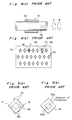
- Figs. 4 (a) and (b) Japanese Utility Model Publication No. 12971/1991.
- Fig. 4 (a) is a cross sectional view in the axial direction of the dynamic pressure bearing device
- Fig. 4 (b) is a development view showing a sliding surface of the inner circumference of a bearing in the dynamic pressure bearing device.
- This dynamic pressure bearing device has a column-shaped shaft 52 partly accommodated into a cylindrical bearing 51. Although not shown, oil as a lubricating fluid is charged between the bearing 51 and the shaft 52. Also, a plurality of rhombus dynamic pressure grooves 55 are provided to a sliding surface 53 of the inner circumference of the bearing 51 confronting the shaft 52, as shown in Fig. 4 (b).
- the rhombus dynamic pressure grooves 55 are positioned on the sliding surface 53 in such a manner that, of two orthogonal line segments L and M formed by joining the opposing vertexes of the rhombus dynamic pressure groove 55, one line segment L extends in the circumferential direction of the shaft 52 while the other line segment M extends in the axial direction of the shaft 52.
- the object of the present invention is therefore to provide a dynamic pressure bearing device which can cause a flow of fluid within its dynamic pressure grooves to be smooth when the direction of relative movement between shaft and bearing is reversed and moreover which can generate dynamic pressure of approximately equal level whatever the direction of movement is.
- a dynamic pressure bearing device wherein a shaft is partly accommodated into a bearing, characterized in that: at least one of a sliding surface of the shaft confronting the bearing and a sliding surface of the bearing confronting the shaft is provided with dynamic pressure grooves of approximately circular shape for causing a fluid between the bearing and the shaft to generate a dynamic pressure.
- dynamic pressure grooves are of approximately circular shape they are able to generate dynamic pressure of approximately equal level whatever is the direction of relative movement between the bearing and the shaft with respect to the dynamic pressure grooves. Therefore, it is possible to generate dynamic pressure of approximately equal level whatever the above-noted direction of movement is.
- the fluid within the dynamic pressure grooves will change its flowing direction smoothly into reverse along the dynamic pressure grooves of approximately circular shape. Therefore, the dynamic pressure generated can be prevented from fluctuating when the above-noted direction of movement is reversed.
- the taper grooves serve as a fluid reservoir for the fluid between the bearing and the shaft while the fluid present in the taper grooves will ascend slant surfaces of up slope toward the axial insides of the taper grooves by virtue of a centrifugal force applied to the fluid in the relative rotation between the bearing and the shaft. That is, the fluid at both axial ends of the sliding surface is made to move toward the axial insides, respectively, while the above-noted rotation is effected, so that the fluid can be suppressed from leaking out from between the bearing and the shaft, thus improving the sealing characteristic for the fluid.
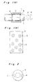
- Figs. 1 (a) and (b) show an embodiment of a dynamic pressure bearing device according to the present invention.
- the embodiment is so arranged that a column-shaped shaft 2 is partly accommodated into a cylindrical bearing 1.
- a sliding surface 3 of the inner circumference of the bearing 1 confronting the shaft 2 is provided with a plurality of circular dynamic pressure grooves 5, 5 ..., as shown in Fig. 1 (b).
- oil is charged between the bearing 1 and the shaft 2 is charged oil as a lubricating fluid (not shown).
- taper grooves 4, 4 are provided to both axial ends of the sliding surface of the shaft 2 confronting the bearing 1 in such a manner that the grooves 4, 4 increasingly deepen toward axial outsides, respectively.
- the dynamic pressure grooves 5 cause the oil within the dynamic pressure grooves 5 to form two flows in the same direction as the direction B indicated by the arrow B to make the oil generate a dynamic pressure, thereby supporting the shaft 2 in the radial direction.
- the oil within the dynamic pressure grooves 5 can smoothly change its flowing direction into reverse along the circular shaped dynamic pressure grooves 5. Accordingly, it is possible to prevent the dynamic pressure generated from fluctuating when the rotating direction is reversed.
- the dynamic pressure grooves 5 are of circular shape, the grooves are capable of generating dynamic pressure of equal level whatever the direction of relative movement between the bearing 1 and the shaft 2 is. Therefore, according to the present embodiment, it is possible to generate dynamic pressure of equal level whichever the above-noted relative movement is either linear movement in the axial direction or spiral movement. It is also possible to increase the degree of freedom for positioning the dynamic pressure grooves 5 to the sliding surface 3.
- the taper grooves 4, 4 are provided to both axial ends of the sliding surface of the shaft 2 confronting the bearing 1 in such a manner that the grooves 4, 4 increasingly deepen toward the axial outsides, respectively, the taper grooves 4, 4 serve as an oil reservoir for the oil between the bearing 1 and the shaft 2 while the oil will ascend the slant surfaces of up slope toward the axial insides of the taper grooves 4, 4 by virtue of a centrifugal force applied to the oil in the relative rotation between the bearing 1 and the shaft 2.
- the oil at both axial ends of the sliding surface is made to move toward the axial insides in the above-noted relative rotation, so that the oil can be suppressed from leaking out from between the bearing 1 and the shaft 2, thus improving the sealing characteristic for the oil.
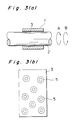
- Figs. 3 (a) and (b) is a dynamic pressure bearing device in which no taper grooves 4, 4 are provided to the shaft 2 in the above-described embodiment.
- dynamic pressure grooves 5 of the above-described embodiment has been formed into circular shape, they may also be of elliptical shape. Further, the dynamic pressure grooves 5, which have been provided to the sliding surface 3 of the bearing 1 in the embodiment, may alternatively be provided to the sliding surface of the shaft 2.
- the dynamic pressure bearing device of the present invention is arranged so that dynamic pressure grooves provided to at least one of a sliding surface of a shaft confronting a bearing and a sliding surface of the bearing confronting the shaft are of approximately circular shape, it is possible to generate dynamic pressure of approximately equal level whatever is the direction of relative movement between the bearing and the shaft with respect to the dynamic pressure grooves.
- the fluid within the dynamic pressure grooves can change its flowing direction into reverse smoothly along the approximately circular dynamic pressure grooves. Therefore, according to the present invention, it is possible to prevent the dynamic pressure generated from fluctuating when the direction of relative movement between bearing and shaft is reversed.
- the taper grooves serve as a fluid reservoir for the fluid between the bearing and the shaft while the fluid will ascend the slant surfaces of up slope toward the axial insides of the taper grooves by virtue of a centrifugal force applied to the fluid in the relative rotation between the bearing and the shaft. That is, the fluid at both axial ends of the sliding surface is made to move toward the axial insides in the above rotation, so that the fluid can be suppressed from leaking out from between the bearing and the shaft, thus improving the sealing characteristic for the fluid.
Landscapes
- Engineering & Computer Science (AREA)
- General Engineering & Computer Science (AREA)
- Mechanical Engineering (AREA)
- Physics & Mathematics (AREA)
- Fluid Mechanics (AREA)
- Chemical & Material Sciences (AREA)
- Oil, Petroleum & Natural Gas (AREA)
- Sliding-Contact Bearings (AREA)
Applications Claiming Priority (4)
| Application Number | Priority Date | Filing Date | Title |
|---|---|---|---|
| JP56437/91U | 1991-07-19 | ||
| JP5643791 | 1991-07-19 | ||
| JP11794/92U | 1992-03-10 | ||
| JP1992011794U JP2573338Y2 (ja) | 1991-07-19 | 1992-03-10 | 動圧軸受 |
Publications (2)
| Publication Number | Publication Date |
|---|---|
| EP0523739A1 true EP0523739A1 (de) | 1993-01-20 |
| EP0523739B1 EP0523739B1 (de) | 1995-09-27 |
Family
ID=26347311
Family Applications (1)
| Application Number | Title | Priority Date | Filing Date |
|---|---|---|---|
| EP92112281A Expired - Lifetime EP0523739B1 (de) | 1991-07-19 | 1992-07-17 | Dynamische Drucklagervorrichtung |
Country Status (4)
| Country | Link |
|---|---|
| US (1) | US5240332A (de) |
| EP (1) | EP0523739B1 (de) |
| JP (1) | JP2573338Y2 (de) |
| DE (1) | DE69205089T2 (de) |
Cited By (1)
| Publication number | Priority date | Publication date | Assignee | Title |
|---|---|---|---|---|
| WO1997028379A3 (de) * | 1996-01-30 | 1997-10-23 | Glyco Metall Werke | Gleitlagerelement mit schmieröltaschen |
Families Citing this family (9)
| Publication number | Priority date | Publication date | Assignee | Title |
|---|---|---|---|---|
| JP2902262B2 (ja) * | 1993-03-29 | 1999-06-07 | 光洋精工株式会社 | 動圧軸受 |
| DE69528281T2 (de) * | 1995-06-02 | 2003-08-07 | Fuji Xerox Co., Ltd. | Hochgeschwindigkeitsrotoranordnung |
| JP3069039B2 (ja) * | 1996-02-02 | 2000-07-24 | 日本電産コパル電子株式会社 | 動圧気体軸受 |
| JP3846034B2 (ja) * | 1997-11-20 | 2006-11-15 | 株式会社デンソー | 軸受け |
| DE19937655B4 (de) * | 1999-08-13 | 2005-06-16 | ZF Lemförder Metallwaren AG | Kugelgelenk |
| US7194995B2 (en) * | 2004-05-14 | 2007-03-27 | Menard Competition Technologies, Ltd. | Bearing |
| US7878777B2 (en) * | 2006-08-25 | 2011-02-01 | Denso Corporation | Scroll compressor having grooved thrust bearing |
| US8192086B1 (en) * | 2009-07-09 | 2012-06-05 | Florida Turbine Technologies, Inc. | Air bearing |
| KR102449381B1 (ko) * | 2014-03-04 | 2022-10-05 | 포라이트 가부시키가이샤 | 소결 베어링 |
Citations (6)
| Publication number | Priority date | Publication date | Assignee | Title |
|---|---|---|---|---|
| US3238000A (en) * | 1962-09-06 | 1966-03-01 | Philips Corp | Radial sliding bearing for traversing shafts |
| CH447863A (de) * | 1965-03-18 | 1967-11-30 | Deckel Hans Dr Ing | Anwendung eines Verfahrens zur Herstellung von Öltaschen auf Gleitflächen von Maschinenteilen |
| DE2036036A1 (de) * | 1969-07-22 | 1971-02-11 | Nederlandse Orgamsatie voor Toege past Natuurwetenschappehjk Onderzoek ten behoeve van Nijverheid, Handel en Verkeer Den Haag | Lager und Dichtungen mit gerillter Lagerflache |
| US3778123A (en) * | 1971-11-17 | 1973-12-11 | Singer Co | Liquid bearing unit and seal |
| FR2193441A5 (de) * | 1972-07-13 | 1974-02-15 | Bosch Gmbh Robert | |
| DE2711983A1 (de) * | 1976-03-19 | 1977-09-22 | Daido Metal Co Ltd | Lager |
Family Cites Families (10)
| Publication number | Priority date | Publication date | Assignee | Title |
|---|---|---|---|---|
| US2187626A (en) * | 1938-07-02 | 1940-01-16 | Merriman Brothers Inc | Self-lubricating bearing |
| US2680259A (en) * | 1951-06-04 | 1954-06-08 | Merriman Bros Inc | Self-lubricating bearing for heavy loads |
| DE1450034A1 (de) * | 1964-05-02 | 1969-09-04 | Schmidt Gmbh Karl | Gleitlager mit Schmiermittelnuten |
| US3976342A (en) * | 1972-07-13 | 1976-08-24 | Robert Bosch G.M.B.H. | Method and apparatus for reducing fretting wear between relatively moving parts |
| FR2532382B1 (fr) * | 1982-08-25 | 1987-01-30 | Nippon Seiko Kk | Guidage a rainures de lubrification pour mouvement rectiligne |
| JPS621886A (ja) * | 1985-06-25 | 1987-01-07 | Matsushita Electric Ind Co Ltd | 流体軸受シヤフト |
| JPH07113370B2 (ja) * | 1986-12-26 | 1995-12-06 | 松下電器産業株式会社 | 動圧型流体軸受 |
| JPH07101746B2 (ja) * | 1989-06-12 | 1995-11-01 | 三菱電機株式会社 | 半導体装置の製造方法 |
| JPH0331929A (ja) * | 1989-06-29 | 1991-02-12 | Fujitsu Ltd | 演算装置 |
| GB2235736B (en) * | 1989-08-09 | 1993-09-15 | Nippon Seiko Kk | Bearing with dynamic pressure grooves and method for manufacturing the same |
-
1992
- 1992-03-10 JP JP1992011794U patent/JP2573338Y2/ja not_active Expired - Lifetime
- 1992-07-16 US US07/913,898 patent/US5240332A/en not_active Expired - Lifetime
- 1992-07-17 DE DE69205089T patent/DE69205089T2/de not_active Expired - Fee Related
- 1992-07-17 EP EP92112281A patent/EP0523739B1/de not_active Expired - Lifetime
Patent Citations (6)
| Publication number | Priority date | Publication date | Assignee | Title |
|---|---|---|---|---|
| US3238000A (en) * | 1962-09-06 | 1966-03-01 | Philips Corp | Radial sliding bearing for traversing shafts |
| CH447863A (de) * | 1965-03-18 | 1967-11-30 | Deckel Hans Dr Ing | Anwendung eines Verfahrens zur Herstellung von Öltaschen auf Gleitflächen von Maschinenteilen |
| DE2036036A1 (de) * | 1969-07-22 | 1971-02-11 | Nederlandse Orgamsatie voor Toege past Natuurwetenschappehjk Onderzoek ten behoeve van Nijverheid, Handel en Verkeer Den Haag | Lager und Dichtungen mit gerillter Lagerflache |
| US3778123A (en) * | 1971-11-17 | 1973-12-11 | Singer Co | Liquid bearing unit and seal |
| FR2193441A5 (de) * | 1972-07-13 | 1974-02-15 | Bosch Gmbh Robert | |
| DE2711983A1 (de) * | 1976-03-19 | 1977-09-22 | Daido Metal Co Ltd | Lager |
Cited By (1)
| Publication number | Priority date | Publication date | Assignee | Title |
|---|---|---|---|---|
| WO1997028379A3 (de) * | 1996-01-30 | 1997-10-23 | Glyco Metall Werke | Gleitlagerelement mit schmieröltaschen |
Also Published As
| Publication number | Publication date |
|---|---|
| DE69205089T2 (de) | 1996-05-15 |
| JPH0525021U (ja) | 1993-04-02 |
| EP0523739B1 (de) | 1995-09-27 |
| US5240332A (en) | 1993-08-31 |
| JP2573338Y2 (ja) | 1998-05-28 |
| DE69205089D1 (de) | 1995-11-02 |
Similar Documents
| Publication | Publication Date | Title |
|---|---|---|
| CN113439167B (zh) | 滑动部件 | |
| KR102646386B1 (ko) | 슬라이딩 부품 | |
| JP6861730B2 (ja) | しゅう動部品 | |
| US5174583A (en) | Unitary bearing seal | |
| US5427456A (en) | Fluid bearing with asymmetrical groove pattern | |
| US5224714A (en) | Noncontacting face seal | |
| EP0466076A2 (de) | Spiralrillengleitringdichtung | |
| JPH0628335U (ja) | 動圧軸受装置 | |
| US5240332A (en) | Dynamic pressure bearing device | |
| JPH03149410A (ja) | 動圧軸受装置 | |
| MXPA05003406A (es) | Elemento unificador y metodo para ensamblar un sello. | |
| CN101893092A (zh) | 可双向旋转的气体润滑非接触式机械密封装置 | |
| CN211288754U (zh) | 浮环密封装置 | |
| US7940492B2 (en) | Hydrodynamic bearing device, spindle motor, and recording and reproducing apparatus | |
| US6182972B1 (en) | Unitary bearing seal | |
| JPS59102568A (ja) | 鋳鉄製シ−ル・リングを製造する方法 | |
| JPS59144859A (ja) | 回転可能な軸の密封装置 | |
| US5667308A (en) | Bearing device for use in a motor | |
| CN201696617U (zh) | 可双向旋转的气体润滑非接触式机械密封装置 | |
| WO2024142919A1 (ja) | 摺動部品 | |
| WO2024142918A1 (ja) | 摺動部品 | |
| JP2001116046A (ja) | 動圧軸受装置 | |
| JPS60121308A (ja) | 動圧形の複合軸受装置 | |
| CN203979126U (zh) | 带密封的整体四点接触球轴承 | |
| US6592490B2 (en) | Well pump gear box hydrodynamic washer |
Legal Events
| Date | Code | Title | Description |
|---|---|---|---|
| PUAI | Public reference made under article 153(3) epc to a published international application that has entered the european phase |
Free format text: ORIGINAL CODE: 0009012 |
|
| AK | Designated contracting states |
Kind code of ref document: A1 Designated state(s): DE FR NL |
|
| 17P | Request for examination filed |
Effective date: 19930720 |
|
| 17Q | First examination report despatched |
Effective date: 19931223 |
|
| GRAA | (expected) grant |
Free format text: ORIGINAL CODE: 0009210 |
|
| AK | Designated contracting states |
Kind code of ref document: B1 Designated state(s): DE FR NL |
|
| REF | Corresponds to: |
Ref document number: 69205089 Country of ref document: DE Date of ref document: 19951102 |
|
| ET | Fr: translation filed | ||
| PLBE | No opposition filed within time limit |
Free format text: ORIGINAL CODE: 0009261 |
|
| STAA | Information on the status of an ep patent application or granted ep patent |
Free format text: STATUS: NO OPPOSITION FILED WITHIN TIME LIMIT |
|
| 26N | No opposition filed | ||
| PGFP | Annual fee paid to national office [announced via postgrant information from national office to epo] |
Ref country code: DE Payment date: 20080724 Year of fee payment: 17 |
|
| PGFP | Annual fee paid to national office [announced via postgrant information from national office to epo] |
Ref country code: NL Payment date: 20080715 Year of fee payment: 17 Ref country code: FR Payment date: 20080718 Year of fee payment: 17 |
|
| NLV4 | Nl: lapsed or anulled due to non-payment of the annual fee |
Effective date: 20100201 |
|
| REG | Reference to a national code |
Ref country code: FR Ref legal event code: ST Effective date: 20100331 |
|
| PG25 | Lapsed in a contracting state [announced via postgrant information from national office to epo] |
Ref country code: FR Free format text: LAPSE BECAUSE OF NON-PAYMENT OF DUE FEES Effective date: 20090731 |
|
| PG25 | Lapsed in a contracting state [announced via postgrant information from national office to epo] |
Ref country code: DE Free format text: LAPSE BECAUSE OF NON-PAYMENT OF DUE FEES Effective date: 20100202 |
|
| PG25 | Lapsed in a contracting state [announced via postgrant information from national office to epo] |
Ref country code: NL Free format text: LAPSE BECAUSE OF NON-PAYMENT OF DUE FEES Effective date: 20100201 |