EP0529795B1 - Magnetooptisches Aufzeichnungsmedium - Google Patents
Magnetooptisches Aufzeichnungsmedium Download PDFInfo
- Publication number
- EP0529795B1 EP0529795B1 EP92306650A EP92306650A EP0529795B1 EP 0529795 B1 EP0529795 B1 EP 0529795B1 EP 92306650 A EP92306650 A EP 92306650A EP 92306650 A EP92306650 A EP 92306650A EP 0529795 B1 EP0529795 B1 EP 0529795B1
- Authority
- EP
- European Patent Office
- Prior art keywords
- layer
- layers
- medium according
- film
- recording medium
- Prior art date
- Legal status (The legal status is an assumption and is not a legal conclusion. Google has not performed a legal analysis and makes no representation as to the accuracy of the status listed.)
- Expired - Lifetime
Links
- 239000000758 substrate Substances 0.000 claims description 12
- 229910052697 platinum Inorganic materials 0.000 claims description 10
- 229910052763 palladium Inorganic materials 0.000 claims description 9
- 229910052693 Europium Inorganic materials 0.000 claims description 5
- 229910052689 Holmium Inorganic materials 0.000 claims description 5
- 229910052779 Neodymium Inorganic materials 0.000 claims description 5
- 229910052772 Samarium Inorganic materials 0.000 claims description 5
- 229910052771 Terbium Inorganic materials 0.000 claims description 5
- 229910052732 germanium Inorganic materials 0.000 claims description 5
- 229910052742 iron Inorganic materials 0.000 claims description 5
- 229910052710 silicon Inorganic materials 0.000 claims description 5
- 229910052718 tin Inorganic materials 0.000 claims description 5
- 229910052692 Dysprosium Inorganic materials 0.000 claims description 4
- 229910052688 Gadolinium Inorganic materials 0.000 claims description 4
- VYPSYNLAJGMNEJ-UHFFFAOYSA-N Silicium dioxide Chemical compound O=[Si]=O VYPSYNLAJGMNEJ-UHFFFAOYSA-N 0.000 claims description 4
- MCMNRKCIXSYSNV-UHFFFAOYSA-N Zirconium dioxide Chemical compound O=[Zr]=O MCMNRKCIXSYSNV-UHFFFAOYSA-N 0.000 claims description 4
- WMWLMWRWZQELOS-UHFFFAOYSA-N bismuth(iii) oxide Chemical compound O=[Bi]O[Bi]=O WMWLMWRWZQELOS-UHFFFAOYSA-N 0.000 claims description 4
- 229910052741 iridium Inorganic materials 0.000 claims description 4
- 239000000463 material Substances 0.000 claims description 4
- 229910052759 nickel Inorganic materials 0.000 claims description 4
- 229910052684 Cerium Inorganic materials 0.000 claims description 3
- 229910052691 Erbium Inorganic materials 0.000 claims description 3
- 229910052777 Praseodymium Inorganic materials 0.000 claims description 3
- 229910052782 aluminium Inorganic materials 0.000 claims description 3
- 229910052787 antimony Inorganic materials 0.000 claims description 3
- 229910052799 carbon Inorganic materials 0.000 claims description 3
- 229910052802 copper Inorganic materials 0.000 claims description 3
- 229910052733 gallium Inorganic materials 0.000 claims description 3
- 229910052738 indium Inorganic materials 0.000 claims description 3
- 229910052750 molybdenum Inorganic materials 0.000 claims description 3
- 229910052758 niobium Inorganic materials 0.000 claims description 3
- 229910052698 phosphorus Inorganic materials 0.000 claims description 3
- 229910052719 titanium Inorganic materials 0.000 claims description 3
- 229910052720 vanadium Inorganic materials 0.000 claims description 3
- 229910052726 zirconium Inorganic materials 0.000 claims description 3
- 229910017083 AlN Inorganic materials 0.000 claims description 2
- 102100032047 Alsin Human genes 0.000 claims description 2
- 101710187109 Alsin Proteins 0.000 claims description 2
- 229910052581 Si3N4 Inorganic materials 0.000 claims description 2
- ATJFFYVFTNAWJD-UHFFFAOYSA-N Tin Chemical compound [Sn] ATJFFYVFTNAWJD-UHFFFAOYSA-N 0.000 claims description 2
- 229910008322 ZrN Inorganic materials 0.000 claims description 2
- PNEYBMLMFCGWSK-UHFFFAOYSA-N aluminium oxide Inorganic materials [O-2].[O-2].[O-2].[Al+3].[Al+3] PNEYBMLMFCGWSK-UHFFFAOYSA-N 0.000 claims description 2
- 229910052797 bismuth Inorganic materials 0.000 claims description 2
- 229910052804 chromium Inorganic materials 0.000 claims description 2
- 229910052681 coesite Inorganic materials 0.000 claims description 2
- 229910052593 corundum Inorganic materials 0.000 claims description 2
- 229910052906 cristobalite Inorganic materials 0.000 claims description 2
- 229910052737 gold Inorganic materials 0.000 claims description 2
- 229910052735 hafnium Inorganic materials 0.000 claims description 2
- JEIPFZHSYJVQDO-UHFFFAOYSA-N iron(III) oxide Inorganic materials O=[Fe]O[Fe]=O JEIPFZHSYJVQDO-UHFFFAOYSA-N 0.000 claims description 2
- 229910052745 lead Inorganic materials 0.000 claims description 2
- CPLXHLVBOLITMK-UHFFFAOYSA-N magnesium oxide Inorganic materials [Mg]=O CPLXHLVBOLITMK-UHFFFAOYSA-N 0.000 claims description 2
- 229910052748 manganese Inorganic materials 0.000 claims description 2
- 229910052703 rhodium Inorganic materials 0.000 claims description 2
- SBIBMFFZSBJNJF-UHFFFAOYSA-N selenium;zinc Chemical compound [Se]=[Zn] SBIBMFFZSBJNJF-UHFFFAOYSA-N 0.000 claims description 2
- 239000000377 silicon dioxide Substances 0.000 claims description 2
- 229910052709 silver Inorganic materials 0.000 claims description 2
- 229910052682 stishovite Inorganic materials 0.000 claims description 2
- PBCFLUZVCVVTBY-UHFFFAOYSA-N tantalum pentoxide Inorganic materials O=[Ta](=O)O[Ta](=O)=O PBCFLUZVCVVTBY-UHFFFAOYSA-N 0.000 claims description 2
- 229910052905 tridymite Inorganic materials 0.000 claims description 2
- 229910052721 tungsten Inorganic materials 0.000 claims description 2
- 229910001845 yogo sapphire Inorganic materials 0.000 claims description 2
- 229910052727 yttrium Inorganic materials 0.000 claims description 2
- 229910052725 zinc Inorganic materials 0.000 claims description 2
- 239000010408 film Substances 0.000 description 52
- BASFCYQUMIYNBI-UHFFFAOYSA-N platinum Chemical group [Pt] BASFCYQUMIYNBI-UHFFFAOYSA-N 0.000 description 21
- 229910052761 rare earth metal Inorganic materials 0.000 description 17
- 150000002910 rare earth metals Chemical class 0.000 description 11
- 238000010030 laminating Methods 0.000 description 8
- 230000005415 magnetization Effects 0.000 description 8
- 229910020708 Co—Pd Inorganic materials 0.000 description 6
- 229910020707 Co—Pt Inorganic materials 0.000 description 6
- 229910052751 metal Inorganic materials 0.000 description 6
- 239000002184 metal Substances 0.000 description 6
- 239000010409 thin film Substances 0.000 description 6
- 239000011521 glass Substances 0.000 description 4
- 238000000034 method Methods 0.000 description 4
- 239000004065 semiconductor Substances 0.000 description 4
- 229910018879 Pt—Pd Inorganic materials 0.000 description 3
- 229910045601 alloy Inorganic materials 0.000 description 3
- 239000000956 alloy Substances 0.000 description 3
- 238000010276 construction Methods 0.000 description 3
- 238000005260 corrosion Methods 0.000 description 3
- 230000007797 corrosion Effects 0.000 description 3
- 239000003989 dielectric material Substances 0.000 description 3
- 238000004544 sputter deposition Methods 0.000 description 3
- -1 Al2O3 Chemical class 0.000 description 2
- 229910000808 amorphous metal alloy Inorganic materials 0.000 description 2
- 230000008859 change Effects 0.000 description 2
- 150000001875 compounds Chemical class 0.000 description 2
- 230000008878 coupling Effects 0.000 description 2
- 238000010168 coupling process Methods 0.000 description 2
- 238000005859 coupling reaction Methods 0.000 description 2
- 230000007423 decrease Effects 0.000 description 2
- 230000000694 effects Effects 0.000 description 2
- 239000000203 mixture Substances 0.000 description 2
- 230000005374 Kerr effect Effects 0.000 description 1
- 229910021069 Pd—Co Inorganic materials 0.000 description 1
- FAPWRFPIFSIZLT-UHFFFAOYSA-M Sodium chloride Chemical compound [Na+].[Cl-] FAPWRFPIFSIZLT-UHFFFAOYSA-M 0.000 description 1
- 238000007796 conventional method Methods 0.000 description 1
- 238000000151 deposition Methods 0.000 description 1
- 230000008021 deposition Effects 0.000 description 1
- 239000000696 magnetic material Substances 0.000 description 1
- 238000001755 magnetron sputter deposition Methods 0.000 description 1
- 239000007769 metal material Substances 0.000 description 1
- 238000001451 molecular beam epitaxy Methods 0.000 description 1
- 150000004767 nitrides Chemical class 0.000 description 1
- 239000004033 plastic Substances 0.000 description 1
- 229920003023 plastic Polymers 0.000 description 1
- 238000004321 preservation Methods 0.000 description 1
- 230000008569 process Effects 0.000 description 1
- 229910052723 transition metal Inorganic materials 0.000 description 1
- 239000012780 transparent material Substances 0.000 description 1
- 238000007738 vacuum evaporation Methods 0.000 description 1
Images


Classifications
-
- G—PHYSICS
- G11—INFORMATION STORAGE
- G11B—INFORMATION STORAGE BASED ON RELATIVE MOVEMENT BETWEEN RECORD CARRIER AND TRANSDUCER
- G11B11/00—Recording on or reproducing from the same record carrier wherein for these two operations the methods are covered by different main groups of groups G11B3/00 - G11B7/00 or by different subgroups of group G11B9/00; Record carriers therefor
- G11B11/10—Recording on or reproducing from the same record carrier wherein for these two operations the methods are covered by different main groups of groups G11B3/00 - G11B7/00 or by different subgroups of group G11B9/00; Record carriers therefor using recording by magnetic means or other means for magnetisation or demagnetisation of a record carrier, e.g. light induced spin magnetisation; Demagnetisation by thermal or stress means in the presence or not of an orienting magnetic field
- G11B11/105—Recording on or reproducing from the same record carrier wherein for these two operations the methods are covered by different main groups of groups G11B3/00 - G11B7/00 or by different subgroups of group G11B9/00; Record carriers therefor using recording by magnetic means or other means for magnetisation or demagnetisation of a record carrier, e.g. light induced spin magnetisation; Demagnetisation by thermal or stress means in the presence or not of an orienting magnetic field using a beam of light or a magnetic field for recording by change of magnetisation and a beam of light for reproducing, i.e. magneto-optical, e.g. light-induced thermomagnetic recording, spin magnetisation recording, Kerr or Faraday effect reproducing
- G11B11/10582—Record carriers characterised by the selection of the material or by the structure or form
- G11B11/10584—Record carriers characterised by the selection of the material or by the structure or form characterised by the form, e.g. comprising mechanical protection elements
-
- G—PHYSICS
- G11—INFORMATION STORAGE
- G11B—INFORMATION STORAGE BASED ON RELATIVE MOVEMENT BETWEEN RECORD CARRIER AND TRANSDUCER
- G11B11/00—Recording on or reproducing from the same record carrier wherein for these two operations the methods are covered by different main groups of groups G11B3/00 - G11B7/00 or by different subgroups of group G11B9/00; Record carriers therefor
- G11B11/10—Recording on or reproducing from the same record carrier wherein for these two operations the methods are covered by different main groups of groups G11B3/00 - G11B7/00 or by different subgroups of group G11B9/00; Record carriers therefor using recording by magnetic means or other means for magnetisation or demagnetisation of a record carrier, e.g. light induced spin magnetisation; Demagnetisation by thermal or stress means in the presence or not of an orienting magnetic field
- G11B11/105—Recording on or reproducing from the same record carrier wherein for these two operations the methods are covered by different main groups of groups G11B3/00 - G11B7/00 or by different subgroups of group G11B9/00; Record carriers therefor using recording by magnetic means or other means for magnetisation or demagnetisation of a record carrier, e.g. light induced spin magnetisation; Demagnetisation by thermal or stress means in the presence or not of an orienting magnetic field using a beam of light or a magnetic field for recording by change of magnetisation and a beam of light for reproducing, i.e. magneto-optical, e.g. light-induced thermomagnetic recording, spin magnetisation recording, Kerr or Faraday effect reproducing
- G11B11/10582—Record carriers characterised by the selection of the material or by the structure or form
- G11B11/10586—Record carriers characterised by the selection of the material or by the structure or form characterised by the selection of the material
-
- Y—GENERAL TAGGING OF NEW TECHNOLOGICAL DEVELOPMENTS; GENERAL TAGGING OF CROSS-SECTIONAL TECHNOLOGIES SPANNING OVER SEVERAL SECTIONS OF THE IPC; TECHNICAL SUBJECTS COVERED BY FORMER USPC CROSS-REFERENCE ART COLLECTIONS [XRACs] AND DIGESTS
- Y10—TECHNICAL SUBJECTS COVERED BY FORMER USPC
- Y10S—TECHNICAL SUBJECTS COVERED BY FORMER USPC CROSS-REFERENCE ART COLLECTIONS [XRACs] AND DIGESTS
- Y10S428/00—Stock material or miscellaneous articles
- Y10S428/922—Static electricity metal bleed-off metallic stock
- Y10S428/9265—Special properties
- Y10S428/928—Magnetic property
-
- Y—GENERAL TAGGING OF NEW TECHNOLOGICAL DEVELOPMENTS; GENERAL TAGGING OF CROSS-SECTIONAL TECHNOLOGIES SPANNING OVER SEVERAL SECTIONS OF THE IPC; TECHNICAL SUBJECTS COVERED BY FORMER USPC CROSS-REFERENCE ART COLLECTIONS [XRACs] AND DIGESTS
- Y10—TECHNICAL SUBJECTS COVERED BY FORMER USPC
- Y10T—TECHNICAL SUBJECTS COVERED BY FORMER US CLASSIFICATION
- Y10T428/00—Stock material or miscellaneous articles
- Y10T428/12—All metal or with adjacent metals
- Y10T428/12465—All metal or with adjacent metals having magnetic properties, or preformed fiber orientation coordinate with shape
-
- Y—GENERAL TAGGING OF NEW TECHNOLOGICAL DEVELOPMENTS; GENERAL TAGGING OF CROSS-SECTIONAL TECHNOLOGIES SPANNING OVER SEVERAL SECTIONS OF THE IPC; TECHNICAL SUBJECTS COVERED BY FORMER USPC CROSS-REFERENCE ART COLLECTIONS [XRACs] AND DIGESTS
- Y10—TECHNICAL SUBJECTS COVERED BY FORMER USPC
- Y10T—TECHNICAL SUBJECTS COVERED BY FORMER US CLASSIFICATION
- Y10T428/00—Stock material or miscellaneous articles
- Y10T428/12—All metal or with adjacent metals
- Y10T428/12493—Composite; i.e., plural, adjacent, spatially distinct metal components [e.g., layers, joint, etc.]
- Y10T428/12632—Four or more distinct components with alternate recurrence of each type component
-
- Y—GENERAL TAGGING OF NEW TECHNOLOGICAL DEVELOPMENTS; GENERAL TAGGING OF CROSS-SECTIONAL TECHNOLOGIES SPANNING OVER SEVERAL SECTIONS OF THE IPC; TECHNICAL SUBJECTS COVERED BY FORMER USPC CROSS-REFERENCE ART COLLECTIONS [XRACs] AND DIGESTS
- Y10—TECHNICAL SUBJECTS COVERED BY FORMER USPC
- Y10T—TECHNICAL SUBJECTS COVERED BY FORMER US CLASSIFICATION
- Y10T428/00—Stock material or miscellaneous articles
- Y10T428/12—All metal or with adjacent metals
- Y10T428/12493—Composite; i.e., plural, adjacent, spatially distinct metal components [e.g., layers, joint, etc.]
- Y10T428/12771—Transition metal-base component
- Y10T428/12861—Group VIII or IB metal-base component
- Y10T428/12875—Platinum group metal-base component
Definitions
- the invention relates to a magnetooptic recording medium for recording and/or reproducing information by a laser beam or the like by utilizing a magneto-optical effect and, more particularly, to a magnetooptic recording medium of an artificial lattice film system having a good vertical magnetic anisotropy and a high coercive force.
- an amorphous alloy comprising a combination of a rare earth element such as Gd, Tb, Dy, or the like and a transition metal element such as Fe, Co, or the like.
- a rare earth element such as Gd, Tb, Dy, or the like
- a transition metal element such as Fe, Co, or the like.
- a recording material of the Co-Pt system or Co-Pd system using a platinum group metal such as Pt, Pd, or the like in place of the rare earth element has an excellent corrosion resistance.
- Techniques for raising the coercive force by using those systems as artificial lattice films are disclosed in JP-A-1-98144, JP-A-1-162257, and the like.
- a coercive force of about 7960 to 15900 Am -1 (100 to 200 Oe) is obtained in case of the artificial lattice film of the Co-Pt system and a coercive force of about 39800 to 159000 Am -1 (500 to 2000 Oe) is obtained in case of the artificial lattice film of the Co-Pd system, so that vertical magnetic films are realized.
- the artificial lattice film is what is called a super lattice film or modulation structural film and is a film in which a plurality of layers which are made of different components and have a thickness of several tens of atomic layers or less are regularly repetitively laminated so as to each have a predetermined thickness.
- the conventional magnetooptic recording medium using the foregoing artificial lattice film as a recording layer has a problem such that a magnitude of the coercive force of the recording layer and a magnitude of the vertical magnetic anisotropy are still insufficient to stably execute a magnetooptic recording.
- US-A-4992336 discloses a magneto-optical recording medium with a recording layer comprising laminated thin films including a thin film of Dy having adjacent to both surfaces thereof a thin film of Co as the upper and lower layers and in addition a thin film of Fe, Co or Ni.
- EP-A-0376375 discloses a recording element including a plurality of magnetic Co-containing layers and a plurality of non-magnetic layers.
- Patent Abstracts of Japan, Vol 13, No. 430, p-937, corresponding to JP-A-1 162 257 additionally discloses a magneto-optical recording medium having thin superlattice metallic films or thin modulation structure metallic films alternately laminated with Co layers and Pt layers.
- the present invention provides a medium as set out in Claim 1.
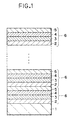
- Fig. 1 is a cross sectional view of an example of a magnetooptic recording medium based on the invention.
- the magnetooptic recording medium shown here is constructed in a manner such that a fundamental unit 6 is formed by sequentially laminating a first Co layer 2 made of Co, a platinum group layer 3 made of a metal selected from Pt, Pd, and Pt-Pd alloy, a second Co layer 4 made of Co, and a rare earth layer 5, an artificial lattice film is formed by repetitively regularly laminating such a fundamental unit 6 a number of times, and the artificial lattice film is used as a recording layer.
- the recording layer is provided on a substrate 1 made of a glass, plastics, or the like.
- the rare earth layer 5 is made of at least one or more kinds of elements selected from Ce, Pr, Nd, Pm, Sm, Eu, Gd, Tb, Dy, Ho, and Er.
- first and second Co layers 2 and 4 are now desirable to set thicknesses of first and second Co layers 2 and 4 to values of about 0.2 to 3nm (2 to 30 ⁇ ), to set a thickness of platinum group layer 3 to a value of about 0.3 to 4nm (3 to 40 ⁇ ), and to set a thickness of rare earth layer 5 to a value of about 0.2 to 3nm (2 to 30 ⁇ ). It is desirable that a thickness of artificial lattice film which has finally been laminated, namely, recording layer is set to a value of about 5 to 80 nm (50 to 800 ⁇ ).
- each interface constructing the above artificial lattice film namely, the interfaces among the first and second Co layers 2 and 4 and the platinum group layer 3 and the interfaces among the first and second Co layers 2 and 4 and the rare earth layer are flat without mutually mixing the atoms in the layers on both sides.
- a composition modulation structure such that the compositions fluctuate while keeping a predetermined period as a whole although slight disturbances occur in the interfaces.
- the above artificial lattice film can be formed by sputtering, vacuum evaporation deposition, molecular beam epitaxy (MBE), or the like.
- various kinds of elements can be also added in order to raise a thermal stability, to change a Curie temperature, or the like.
- an element to be added into each of the Co layers it is preferable to use at least one kind selected from B, C, Al, Si, P, Ti, V, Fe, Ni, Cu, Ga, Ge, Zr, Nb, Mo, In, Sn, and Sb.
- elements which are added into the platinum group layer in addition to the elements similar to those in each Co layer, there can be mentioned Cr, Mn, Co, Zn, Y, Rh, Ag, La, Nd, Sm, Eu, Ho, Hf, W, Ir, Au, Pb, Bi, and the like.
- the recording layer is generally formed on a transparent substrate.
- protecting layers using a metal, a semimetal, a semiconductor, or a dielectric material can be provided on both sides of the recording layer.
- Fig. 2 is a schematic cross sectional view showing the second embodiment of the invention in which such protecting layers are provided.
- Fig. 2 the same component elements as those shown in Fig. 1 are designated by the same reference numerals and their detailed descriptions are omitted here.
- the second embodiment differs from the first embodiment with respect to a point that a first protecting layer 7 is provided between a recording layer which is constructed by periodically laminating a fundamental unit 6 and the substrate 1 and a second protecting layer 8 is provided on the recording layer.
- a metal, a dielectric material, a semimetal, a semiconductor, or the like can be used as materials of the protecting layers 7 and 8.
- a metal material When a metal material is used as protecting layers, it is preferable to provide a film having a thickness of 0.5 to 50nm (5 to 500 ⁇ ) and made of Cu, Rh, Pd, Ag, Ir, Pt, or Au having a face-centered cubic structure or a film having a thickness of 0.5 to 50nm (5 to 500 ⁇ ) and made of W or the like having a body-centered cubic structure.
- a semimetal or a semiconductor it is desirable to provide a film having a thickness of 0.5 to 500nm (5 to 5000 ⁇ ) and made of Si, Ge, ZnSe, SiC, ZnS, or the like.
- Fig. 3 is a schematic cross sectional view showing the third embodiment of the invention having such protecting layers.
- the same component elements as those shown in Fig. 2 are designated by the same reference numerals and their detailed descriptions are omitted here.
- the third embodiment differs from the second embodiment with respect to a point that a reflecting layer 9 is further provided on the second protecting layer 8.
- a reflecting layer 9 is further provided on the second protecting layer 8.
- the recording layer is formed by a super thin film of 20nm (200 ⁇ ) or less, most of the incident light is transmitted through the recording layer.
- the light for recording and reading out enters from the side of the substrate made of a transparent material, by providing the reflecting layer on the side opposite to the recording layer when it is seen from the substrate side, the magneto-optical effect of the light which is transmitted through the recording layer can be sufficiently used.
- a proper metal can be used as such a reflecting layer.
- a structure which is formed by sequentially laminating the first Co layer, platinum group layer, second Co layer, and rare earth layer as mentioned above is used as a fundametnal unit.
- An artificial lattice film is formed by laminating a plurality of such fundamental units.
- a magnetooptic recording medium is formed by using such an artificial lattice film.
- such a magnetooptic recording medium has a large coercive force and a larger vertical magnetic anisotropy in a wide film forming range as compared with those of the conventional artificial lattice film of the Pt-Co system or Pd-Co system.
- Targets of Co, Pt, and Tb each having a diameter of 0.076m (3 inches) are arranged in a magnetron sputtering apparatus, respectively.
- Slide glass substrate is arranged at the position which faces those targets.
- the sputtering is executed under an Ar partial pressure and a condition of a gas pressure of 1.07Pa (8 mTorr), thereby forming recording layers made of artificial lattice films onto the slide glass substrate as shown hereinbelow.
- Samples (Examples 1-1 to 1-4) of the magnetooptic recording medium are formed.
- Sputtering processes are simultaneously performed under conditions such that a DC electric power of 0.1A - 300V is applied to the Co target (first target) and a DC electric power of 0.15A - 300V is applied to the Pt target (second target) and a high frequency electric power of 25W is applied to the Tb target (third target).
- a DC electric power of 0.1A - 300V is applied to the Co target (first target) and a DC electric power of 0.15A - 300V is applied to the Pt target (second target) and a high frequency electric power of 25W is applied to the Tb target (third target).
- artificial lattice films using fundamental units each comprising the first to fourth layers are formed on the slide glass substrates.
- the first layer corresponds to the first Co layer.
- the second layer corresponds to the platinum group layer.
- the third layer corresponds to the second Co layer.
- the fourth layer corresponds to the rare earth layer. Film thicknesses of those first to fourth layers and a total film thickness of the artificial lattice
- a saturation magnetization (10 -3 Am -1 /cc - emu/cc), a coercive force (Am -1 -kOe), a magnetic field (Am -1 _kOe) which is necessary to magnetize and saturate in the direction perpendicular to the film surface, and a Kerr rotational angle (°) from the artificial lattice film surface of each of the samples obtained are measured by using a magnetization measuring device (VSM) of the sample vibrating type and a Kerr effect measuring device using a laser beam of a wavelength of 830 nm.
- VSM magnetization measuring device
- Comparison examples 1-1 to 1-3 An artificial lattice film using a fundamental unit comprising only the first and second layers is formed and samples of the magnetooptic recording medium are formed as Comparison examples 1-1 to 1-3. These Comparison examples correspond to the magnetooptic recording media each of which is made of the conventional artificial lattice film (fundamental unit comprises two layers) of the Co-Pt system. Various kinds of magnetic characteristics are also similarly measured with respect to Comparison examples 1-1 to 1-3. The results are shown in Table 1.
- Samples (Examples 2-1 and 2-2 and Comparison examples 2-1 to 2-7) are formed in a manner similar to Example 1 and Comparison example 1 while changing the materials which are arranged for the targets, film thicknesses of layers, and the like as shown in Table 2.
- the samples formed are also evaluated in a manner similar to Example 1 and Comparison example 1 mentioned above.
- the results are also shown in Table 2.
- "in-plane” in “Remarks” in Table 2 denotes that the sample becomes an in-plane magnetic anisotropic film.
- the fundamental unit comprises four layers and has a construction of the magnetooptic recording medium of the invention.
- the fundamental unit comprises two or three layers and those samples are out of the purview of the invention.
- Comparison examples 2-3 and 2-4 relate to the samples in which rare earth elements which are used in the invention are added to the Co layer of the conventional artificial lattice film of the Co-Pd system.
- the samples of Comparison examples 2-3 and 2-4 are the in-plane anisotropic films.
- Comparison examples 2-5 and 2-6 are formed by adding rare earth elements which are used in the invention into the Pd layer of the conventional artificial lattice film of the Co-Pd system and become the in-plane anisotropic films.
- the fundamental unit of the artificial lattice film comprises three layers which are formed by sequentially laminating the Co layer, platinum group layer, and rare earth layer.
- the sample of comparison example 2-7 is also the in-plane magnetic anisotropic film.
- the reason why the conventional artificial lattice films of the Co-Pt system and Co-Pd system exhibit the vertical magnetic anisotropy is because the film depends on an influence force such as coupling between the atoms in the interface between the Co layer and the Pt or Pd layer, stress distortion in the interface, or the like. It is also known that when a rare earth element is mixed into either one of the layers constructing the conventional artificial lattice film of the Co-Pt system or Co-Pd system or when an intermediate layer made of a rare earth element is inserted between the Co layer and the Pt or Pd layer, the vertical magnetic anisotropy is extinguished. The above phenomena are also shown and will be understood from the results of Comparison examples mentioned above. On the other hand, it is also known that the super thin multi-layer film comprising the Co layer and the rare earth atom layer exhibits a good vertical magnetic anisotropy due to the coupling between the atoms similar to that mentioned above.
- the Co layer and the platinum group layer construct one pair end the Co layer and the rare earth layer also construct another pair. It is expected that a good vertical magnetic anisotropy is obtained without obstructing the vertical magnetic anisotropy which each pair has. As shown in above Examples, a good vertical magnetic anisotropy can be actually obtained.
- the fundamental unit is formed by sequentially laminating the first Co layer made of Co, platinum group layer made of metal selected from Pt, Pd, and Pt-Pd alloy, second Co layer made of Co, and rare earth layer made of at least one or more kinds of elements selected from Ce, Pr, Nd, Pm, Sm, Eu, Gd, Tb, Dy, Ho, and Er.
- the artificial lattice film which is formed by repetitively laminating such fundamental units is used as a recording layer. Consequently, there are advantages such that the coercive force and the vertical magnetic anisotropy are improved and the magnetooptic recording medium having stable characteristics is derived.
Claims (12)
- Magneto-optisches Aufzeichnungsmedium, umfassend ein Substrat (1) und eine Aufzeichnungsschicht, die auf dem Substrat ausgestaltet ist und eine Vielzahl von laminierten Grundeinheiten (6) umfaßt, dadurch gekennzeichnet, daß jede Grundeinheit (6) vier Schichten umfaßt, die in der folgenden Reihe angeordnet sind:eine erste Schicht (2), im wesentlichen bestehend aus Co;eine zweite Schicht (3), im wesentlichen bestehend aus mindestens einem Bestandteil von Pt und Pd;eine dritte Schicht (4), im wesentlichen bestehend aus Co; undeine vierte Schicht (5), im wesentlichen bestehend aus mindestens einem Bestandteil von Ce, Pr, Nd, Pm, Sm, Eu, Gd, Tb, Dy, Ho and Er.
- Medium gemäß Anspruch 1, wobei jede der ersten (2) und dritten (4) Schichten eine Filmdicke im Bereich von 0,2 bis 3 nm (2 bis 30 Å) aufweist.
- Medium gemäß Anspruch 1, wobei die zweite Schicht (3) eine Filmdicke im Bereich von 0,3 bis 4 nm (3 bis 40 Å) aufweist.
- Medium gemäß Anspruch 1, wobei die vierte Schicht (5) eine Filmdicke im Bereich von 0,2 bis 3 nm (2 bis 30 Å) aufweist.
- Medium gemäß Anspruch 1, wobei die Aufzeichnungsschicht eine Filmdicke im Bereich von 5 bis 80 nm (50 bis 800 Å) aufweist.
- Medium gemäß Anspruch 1, wobei mindestens ein Element, ausgewählt aus B, C, Al, Si, P, Ti, V, Fe, Ni, Cu, Ga, Ge, Zr, Nb, Mo, In, Sn und Sb, zu jeder der ersten (2), zweiten (3) und dritten (4) Schichten zugegeben ist.
- Medium gemäß Anspruch 1, wobei mindestens ein Element, ausgewählt aus B, C, Al, Si, P, Ti, V, Fe, Ni, Cu, Ga, Ge, Zr, Nb, Mo, In, Sn, Sb, Cr, Mn, Co, Zn, Y, Rh, Ag, La, Nd, Sm, Eu, Ho, Hf, W, Ir, Au, Pb und Bi, zu der zweiten Schicht (3) zugegeben ist.
- Medium gemäß irgendeinem der vorangehenden Ansprüche, ferner umfassend:eine erste Schutzschicht (7), die zwischen dem Substrat (1) und der Aufzeichnungsschicht ausgestaltet ist, undeine zweite Schutzschicht (8), die auf der Aufzeichnungsschicht angeordnet ist.
- Medium gemäß Anspruch 8, wobei jede der ersten (7) und zweiten (8) Schutzschichten aus einem Material gefertigt ist, das aus Cu, Rh, Pd, Ag, Ir, Pt, Au, W, Al2O3, Ta2O5, MgO, SiO2, Fe2O3, ZrO2, Bi2O3, ZrN, TiN, Si3N4, AlN, AlSiN, BN, TaN, NbN, Si, Ge, ZnSe, SiC und ZnS ausgewählt ist.
- Medium gemäß Anspruch 9, wobei jede der ersten (7) und zweiten (8) Schutzschichten eine Filmdicke im Bereich von 0,5 500 nm (5 bis 5.000 Å) aufweist.
- Medium gemäß irgendeinem der vorangehenden Ansprüche, ferner eine auf der Aufzeichnungsschicht gebildeten Reflexionsschicht (9) umfassend.
- Medium gemäß Anspruch 11, wobei die Aufzeichnungsschicht eine Filmdicke von 20 nm (200 Å) oder weniger aufweist.
Applications Claiming Priority (2)
| Application Number | Priority Date | Filing Date | Title |
|---|---|---|---|
| JP181046/91 | 1991-07-22 | ||
| JP3181046A JP3029485B2 (ja) | 1991-07-22 | 1991-07-22 | 光磁気記録媒体 |
Publications (2)
| Publication Number | Publication Date |
|---|---|
| EP0529795A1 EP0529795A1 (de) | 1993-03-03 |
| EP0529795B1 true EP0529795B1 (de) | 1998-04-01 |
Family
ID=16093827
Family Applications (1)
| Application Number | Title | Priority Date | Filing Date |
|---|---|---|---|
| EP92306650A Expired - Lifetime EP0529795B1 (de) | 1991-07-22 | 1992-07-21 | Magnetooptisches Aufzeichnungsmedium |
Country Status (4)
| Country | Link |
|---|---|
| US (1) | US5370945A (de) |
| EP (1) | EP0529795B1 (de) |
| JP (1) | JP3029485B2 (de) |
| DE (1) | DE69224947T2 (de) |
Families Citing this family (4)
| Publication number | Priority date | Publication date | Assignee | Title |
|---|---|---|---|---|
| JPH06139637A (ja) * | 1992-10-29 | 1994-05-20 | Canon Inc | 光磁気記録媒体 |
| KR0183938B1 (ko) * | 1995-10-28 | 1999-04-15 | 삼성전자주식회사 | 비정질 경희토류-천이금속과 반금속의 합금,이로부터 형성되는 광자기 기록막 및 이 기록막을 채용한 광자기 디스크 |
| US6893542B1 (en) | 1999-09-10 | 2005-05-17 | Seagate Technology Llc | Sputtered multilayer magnetic recording media with ultra-high coercivity |
| JP5479720B2 (ja) * | 2008-12-03 | 2014-04-23 | エイチジーエスティーネザーランドビーブイ | 熱アシスト磁気記録媒体 |
Family Cites Families (21)
| Publication number | Priority date | Publication date | Assignee | Title |
|---|---|---|---|---|
| US4675767A (en) * | 1983-12-12 | 1987-06-23 | Canon Kabushiki Kaisha | Opto-magnetic recording medium |
| JPS60209942A (ja) * | 1984-04-02 | 1985-10-22 | Canon Inc | 熱磁気記録媒体 |
| US4587176A (en) * | 1985-01-14 | 1986-05-06 | E. I. Du Pont De Nemours And Company | Layered coherent structures for magnetic recording |
| US4678721A (en) * | 1986-04-07 | 1987-07-07 | U.S. Philips Corporation | Magnetic recording medium |
| JPS62264463A (ja) * | 1986-05-12 | 1987-11-17 | Fuji Photo Film Co Ltd | 光磁気記録媒体 |
| ATE172047T1 (de) * | 1986-07-08 | 1998-10-15 | Canon Kk | Magnetoptisches aufzeichnungsmedium mit der möglichkeit des überschreibens mit zwei oder mehr magnetschichten und dieses medium verwendende aufzeichnungsmethode |
| JPS63107008A (ja) * | 1986-07-18 | 1988-05-12 | Res Dev Corp Of Japan | 高カ−回転角を有する薄膜及びその製造方法 |
| JP2561655B2 (ja) * | 1987-01-29 | 1996-12-11 | 株式会社日立製作所 | 面内磁気記録媒体 |
| JPH0198144A (ja) * | 1987-10-09 | 1989-04-17 | Sony Corp | 光磁気記録媒体 |
| JPH01162257A (ja) * | 1987-12-18 | 1989-06-26 | Sony Corp | 光磁気記録媒体 |
| DE3803000A1 (de) * | 1988-02-02 | 1989-08-10 | Basf Ag | Flaechenfoermiges, mehrschichtiges magneto-optisches aufzeichnungsmaterial |
| JP2561130B2 (ja) * | 1988-06-27 | 1996-12-04 | 富士写真フイルム株式会社 | 光磁気記録媒体 |
| EP0367685A3 (de) * | 1988-10-31 | 1991-08-07 | Eastman Kodak Company | Magneto-optisches Speichermedium |
| NL8803168A (nl) * | 1988-12-24 | 1990-07-16 | Philips Nv | Werkwijze voor het thermomagnetisch registreren van informatie en het optisch uitlezen van de geregistreerde informatie alsmede een registratie-element dat geschikt is voor toepassing in deze werkwijze. |
| CA2017284C (en) * | 1989-07-04 | 1995-10-03 | Kazutomi Suzuki | Optical recording medium |
| JPH03134833A (ja) * | 1989-10-20 | 1991-06-07 | Hitachi Ltd | 情報記録媒体の構造 |
| JPH03157838A (ja) * | 1989-11-15 | 1991-07-05 | Nikon Corp | 光磁気記録媒体 |
| US5106703A (en) * | 1989-11-27 | 1992-04-21 | Carcia Peter F | Platinum/cobalt multilayer film for magneto-optical recording |
| US5082749A (en) * | 1990-03-15 | 1992-01-21 | E. I. Du Pont De Nemours And Company | Platinum or palladium/cobalt multilayer on a zinc oxide or indium oxide layer for magneto-optical recording |
| JPH0453044A (ja) * | 1990-06-20 | 1992-02-20 | Hitachi Ltd | 光磁気記録媒体 |
| JPH056820A (ja) * | 1990-12-28 | 1993-01-14 | Sony Corp | 光磁気記録媒体 |
-
1991
- 1991-07-22 JP JP3181046A patent/JP3029485B2/ja not_active Expired - Fee Related
-
1992
- 1992-07-21 EP EP92306650A patent/EP0529795B1/de not_active Expired - Lifetime
- 1992-07-21 DE DE69224947T patent/DE69224947T2/de not_active Expired - Fee Related
- 1992-07-21 US US07/915,601 patent/US5370945A/en not_active Expired - Fee Related
Also Published As
| Publication number | Publication date |
|---|---|
| EP0529795A1 (de) | 1993-03-03 |
| JPH0528552A (ja) | 1993-02-05 |
| DE69224947D1 (de) | 1998-05-07 |
| DE69224947T2 (de) | 1998-08-13 |
| JP3029485B2 (ja) | 2000-04-04 |
| US5370945A (en) | 1994-12-06 |
Similar Documents
| Publication | Publication Date | Title |
|---|---|---|
| US6830824B2 (en) | Magnetic recording medium with multiple magnetic layers capable of being exchange coupled at elevated temperatures and magnetic recording apparatus | |
| US5789069A (en) | Magnetic multilayer film and magnetoresistance element | |
| US5510172A (en) | Magnetic multilayer film and magnetoresistance element | |
| JP2738312B2 (ja) | 磁気抵抗効果膜およびその製造方法 | |
| EP0168046A2 (de) | Magnetooptisches Aufzeichnungsmaterial | |
| EP0519949B1 (de) | Platin oder palladium/kobalt mehrschicht auf einer zinkoxid- oder indiumoxidschicht für magnetooptische aufzeichnung | |
| EP0479474B1 (de) | Magneto-optisches Aufzeichnungsmedium | |
| US4995923A (en) | Thin film of amorphous alloy | |
| US5660929A (en) | Perpendicular magnetic recording medium and method of producing same | |
| EP0529795B1 (de) | Magnetooptisches Aufzeichnungsmedium | |
| JPH04167406A (ja) | 光磁気記録媒体 | |
| US5030512A (en) | Magneto-optical recording medium | |
| EP0595636B1 (de) | Magnetooptischer Aufzeichnungsträger | |
| JP2701337B2 (ja) | 光磁気記録媒体 | |
| KR920007319B1 (ko) | 광자기 기록매체 | |
| EP0449252A1 (de) | Magnetooptischer Aufzeichnungsträger | |
| JP2729962B2 (ja) | 光磁気記録媒体 | |
| US5254182A (en) | Thin film of amorphous alloy | |
| JPH0528553A (ja) | 光磁気記録媒体の製造方法および光磁気記録媒体 | |
| JPH0664761B2 (ja) | 光磁気記録媒体 | |
| JPH0676379A (ja) | 光磁気記録媒体 | |
| Uchihara et al. | Thickness dependence of magnetic properties in GdDy/FeCo film | |
| JPH0757310A (ja) | 光磁気薄膜および光磁気記録媒体 | |
| JPH0757309A (ja) | 光磁気薄膜および光磁気記録媒体 | |
| JPH05128603A (ja) | 光磁気記録媒体 |
Legal Events
| Date | Code | Title | Description |
|---|---|---|---|
| PUAI | Public reference made under article 153(3) epc to a published international application that has entered the european phase |
Free format text: ORIGINAL CODE: 0009012 |
|
| AK | Designated contracting states |
Kind code of ref document: A1 Designated state(s): DE FR GB IT NL |
|
| 17P | Request for examination filed |
Effective date: 19930716 |
|
| 17Q | First examination report despatched |
Effective date: 19951103 |
|
| GRAG | Despatch of communication of intention to grant |
Free format text: ORIGINAL CODE: EPIDOS AGRA |
|
| GRAG | Despatch of communication of intention to grant |
Free format text: ORIGINAL CODE: EPIDOS AGRA |
|
| GRAH | Despatch of communication of intention to grant a patent |
Free format text: ORIGINAL CODE: EPIDOS IGRA |
|
| GRAH | Despatch of communication of intention to grant a patent |
Free format text: ORIGINAL CODE: EPIDOS IGRA |
|
| GRAA | (expected) grant |
Free format text: ORIGINAL CODE: 0009210 |
|
| AK | Designated contracting states |
Kind code of ref document: B1 Designated state(s): DE FR GB IT NL |
|
| PG25 | Lapsed in a contracting state [announced via postgrant information from national office to epo] |
Ref country code: NL Free format text: LAPSE BECAUSE OF FAILURE TO SUBMIT A TRANSLATION OF THE DESCRIPTION OR TO PAY THE FEE WITHIN THE PRESCRIBED TIME-LIMIT Effective date: 19980401 Ref country code: IT Free format text: LAPSE BECAUSE OF FAILURE TO SUBMIT A TRANSLATION OF THE DESCRIPTION OR TO PAY THE FEE WITHIN THE PRE;WARNING: LAPSES OF ITALIAN PATENTS WITH EFFECTIVE DATE BEFORE 2007 MAY HAVE OCCURRED AT ANY TIME BEFORE 2007. THE CORRECT EFFECTIVE DATE MAY BE DIFFERENT FROM THE ONE RECORDED.SCRIBED TIME-LIMIT Effective date: 19980401 |
|
| REF | Corresponds to: |
Ref document number: 69224947 Country of ref document: DE Date of ref document: 19980507 |
|
| ET | Fr: translation filed | ||
| NLV1 | Nl: lapsed or annulled due to failure to fulfill the requirements of art. 29p and 29m of the patents act | ||
| PLBE | No opposition filed within time limit |
Free format text: ORIGINAL CODE: 0009261 |
|
| STAA | Information on the status of an ep patent application or granted ep patent |
Free format text: STATUS: NO OPPOSITION FILED WITHIN TIME LIMIT |
|
| 26N | No opposition filed | ||
| REG | Reference to a national code |
Ref country code: GB Ref legal event code: IF02 |
|
| PGFP | Annual fee paid to national office [announced via postgrant information from national office to epo] |
Ref country code: GB Payment date: 20050707 Year of fee payment: 14 |
|
| PGFP | Annual fee paid to national office [announced via postgrant information from national office to epo] |
Ref country code: FR Payment date: 20050719 Year of fee payment: 14 |
|
| PGFP | Annual fee paid to national office [announced via postgrant information from national office to epo] |
Ref country code: DE Payment date: 20050912 Year of fee payment: 14 |
|
| PG25 | Lapsed in a contracting state [announced via postgrant information from national office to epo] |
Ref country code: GB Free format text: LAPSE BECAUSE OF NON-PAYMENT OF DUE FEES Effective date: 20060721 |
|
| PG25 | Lapsed in a contracting state [announced via postgrant information from national office to epo] |
Ref country code: DE Free format text: LAPSE BECAUSE OF NON-PAYMENT OF DUE FEES Effective date: 20070201 |
|
| GBPC | Gb: european patent ceased through non-payment of renewal fee |
Effective date: 20060721 |
|
| REG | Reference to a national code |
Ref country code: FR Ref legal event code: ST Effective date: 20070330 |
|
| PG25 | Lapsed in a contracting state [announced via postgrant information from national office to epo] |
Ref country code: FR Free format text: LAPSE BECAUSE OF NON-PAYMENT OF DUE FEES Effective date: 20060731 |