EP0531994B1 - Appareil de réaction pour analyses biochimique - Google Patents
Appareil de réaction pour analyses biochimique Download PDFInfo
- Publication number
- EP0531994B1 EP0531994B1 EP92115495A EP92115495A EP0531994B1 EP 0531994 B1 EP0531994 B1 EP 0531994B1 EP 92115495 A EP92115495 A EP 92115495A EP 92115495 A EP92115495 A EP 92115495A EP 0531994 B1 EP0531994 B1 EP 0531994B1
- Authority
- EP
- European Patent Office
- Prior art keywords
- reagent
- band
- pair
- shaped conveying
- conveying members
- Prior art date
- Legal status (The legal status is an assumption and is not a legal conclusion. Google has not performed a legal analysis and makes no representation as to the accuracy of the status listed.)
- Expired - Lifetime
Links
Images



Classifications
-
- G—PHYSICS
- G01—MEASURING; TESTING
- G01N—INVESTIGATING OR ANALYSING MATERIALS BY DETERMINING THEIR CHEMICAL OR PHYSICAL PROPERTIES
- G01N35/00—Automatic analysis not limited to methods or materials provided for in any single one of groups G01N1/00 - G01N33/00; Handling materials therefor
- G01N35/00009—Automatic analysis not limited to methods or materials provided for in any single one of groups G01N1/00 - G01N33/00; Handling materials therefor provided with a sample supporting tape, e.g. with absorbent zones
-
- G—PHYSICS
- G01—MEASURING; TESTING
- G01N—INVESTIGATING OR ANALYSING MATERIALS BY DETERMINING THEIR CHEMICAL OR PHYSICAL PROPERTIES
- G01N27/00—Investigating or analysing materials by the use of electric, electrochemical, or magnetic means
- G01N27/26—Investigating or analysing materials by the use of electric, electrochemical, or magnetic means by investigating electrochemical variables; by using electrolysis or electrophoresis
- G01N27/416—Systems
- G01N27/447—Systems using electrophoresis
- G01N27/44704—Details; Accessories
- G01N27/44717—Arrangements for investigating the separated zones, e.g. localising zones
-
- G—PHYSICS
- G01—MEASURING; TESTING
- G01N—INVESTIGATING OR ANALYSING MATERIALS BY DETERMINING THEIR CHEMICAL OR PHYSICAL PROPERTIES
- G01N27/00—Investigating or analysing materials by the use of electric, electrochemical, or magnetic means
- G01N27/26—Investigating or analysing materials by the use of electric, electrochemical, or magnetic means by investigating electrochemical variables; by using electrolysis or electrophoresis
- G01N27/416—Systems
- G01N27/447—Systems using electrophoresis
- G01N27/44756—Apparatus specially adapted therefor
- G01N27/44782—Apparatus specially adapted therefor of a plurality of samples
-
- G—PHYSICS
- G01—MEASURING; TESTING
- G01N—INVESTIGATING OR ANALYSING MATERIALS BY DETERMINING THEIR CHEMICAL OR PHYSICAL PROPERTIES
- G01N27/00—Investigating or analysing materials by the use of electric, electrochemical, or magnetic means
- G01N27/26—Investigating or analysing materials by the use of electric, electrochemical, or magnetic means by investigating electrochemical variables; by using electrolysis or electrophoresis
- G01N27/416—Systems
- G01N27/447—Systems using electrophoresis
Definitions
- the present invention relates to a reaction apparatus for a biochemical examination, designed to supply a reagent appropriately to a support medium such as cellulose acetate film, agarose, agar, or polyacrylamide gel, in an electrophoresis method for biochemical examinations and researches in which a sample for analysis, such as serum protein, isozyme or lipoprotein, is caused to migrate through the support medium, a reagent is reacted with the sample, and the resulting substance is measured.
- a sample for analysis such as serum protein, isozyme or lipoprotein
- the first method is to supply, by means of, say, a pipette 1, drops of a reagent dissolved before use to the entire surface of an electrophoresed support medium 2, as shown in Fig. 1, allow this reagent to be absorbed to the support medium 2 for a certain period of time, and then remove the excess reagent by applying a glass rod 3 or the like, as shown in Fig. 2.
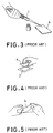
- the second method is to supply, by means of, say, a pipette 1, drops of a reagent dissolved before use to an impregnation membrane 4 such as a filter paper or cellulose acetate membrane, as shown in Fig. 3, allow the reagent to be absorbed thereto, and bring this reagent-impregnated membrane 4 into close contact with an electrophoresed support medium 2, as shown in Figs. 4 and 5.
- an impregnation membrane 4 such as a filter paper or cellulose acetate membrane
- the reaction is performed in an incubator.
- the invention pertains to a reaction apparatus for a biochemical examination as claimed in claim 1.
- a pair of rollers are used to form the closely contacted portions of the band-shaped conveying members.
- This invention also permits a construction in which the pair of band-shaped conveying members are adapted to be capable of moving in normal and reverse directions, a reagent introduction portion for introducing a thin layer reagent supplier having a reagent coated onto the surface of a thin film substrate is connected to one end of the pair of band-shaped conveying members, and an introduction port for the sample-supporting thin film is formed at the other end of the pair of band-shaped conveying members.
- a reagent cartridge capable of introducing one by one a multiplicity of thin layer reagent suppliers placed in a container is detachably mounted to the reagent introduction portion.
- the pair of band-shaped conveying members are constructed of a plastic film
- a horizontal conveying portion of the band-shaped conveying members situated at a lower position of the pair of band-shaped conveying members is formed so as to be longer toward the introduction port than a horizontal conveying portion of the upper band-shaped conveying members in close contact with the former horizontal conveying portion
- a reagent dropping device for dropping a liquid reagent onto the surface of the sample-supporting thin film moving on the extended portion is provided above the extended portion.
- Another construction may also be permitted in which the pair of band-shaped conveying members are constructed of a plastic film, and a reagent is coated onto that surface of one of the band-shaped conveying members which comes into close contact with the sample-supporting thin film.
- the reagent can be supplied uniformly and automatically into the (electrophoresed) support medium, and the sample-supporting member can be placed at a stable reaction temperature, thus making it possible to perform biochemical examinations rapidly and with good reproducibility.
- the thin layer reagent supplier is a special reagent supplier comprising a thin film such as a polyester film onto which a reagent has been coated and dried.
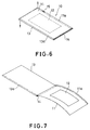
- a thin layer reagent supplier 10 as illustrated here is prepared in the following manner: A reagent-containing agent 12 is adhered to the center of the upper surface of a thin layer substrate (polyester film) 11, whereafter the agent is dried. Then, the substrate 11 is cut into a single strip, and a cover (e.g. a polyester film 38 ⁇ m in thickness) 13 is attached on the coated surface side of the thin layer reagent supplier by heat-sealing at an end 14 thereof (hereinafter referred to as the heat-seal portion). At this time, it is preferred that the cover 13 be slightly displaced from the substrate 11 (e.g. by 10 mm) to form a peel margin 11a and a peel margin 13a in the thin layer substrate 11 and the cover 13, respectively, for easy separation of the cover 13.
- Provision of the cover 13 can prevent the drying and surface contamination of the reagent-containing agent 12 during its reaction. It can also improve close contact of the reagent with the support medium, and prevent contamination of the surrounding devices during close contact.
- the numeral 15 in Fig. 6 is a stop-mark.
- Fig. 7 shows a state of the thin layer reagent supplier 10 in which the peel margin 11a of the thin layer substrate 11 and the peel margin 13a of the cover 13 are engaged separately, and pulled in opposite directions (arrows in Fig. 6), thereby opening the cover 13 and exposing the reagent-containing agent 12.
- Fig. 8 is a sectional block diagram showing an embodiment of the apparatus in accordance with this invention.
- This apparatus is composed of a body 20, and a reagent cartridge 21 which houses a multiplicity of thin layer reagent suppliers 10 therein, and which supplies the thin layer reagent suppliers 10 successively into the body 22.
- the body 20 is L-shaped when viewed sideways, and comprises a reagent introduction portion at a vertical position and a reaction portion 23 at a horizontal position.
- a mounting port 24 for mounting the reagent cartridge 21 is formed below the center of the front surface of the reagent introduction portion 22 (leftward of the drawing).
- the reagent cartridge 21 is a shallow-bottomed box-shaped container, provided at its upper surface with a cover 26 which is openable and closable about a hinge 25 so as to facilitate accommodation of the thin layer reagent supplier 10 from above.
- the cover 26 is not large enough to cover the entire upper surface of the cartridge 21, but is formed to be somewhat shorter so that a supply port 27 to the body 20 can be secured.
- On the inside bottom surface of the cartridge 21 is mounted a push-up plate 29 supported pivotally by a hinge 28 approximately at the center. The forward end of the push-up plate 29 is situated in the supply port 27.
- an insertion port 31 for a push-up spring 30 provided deep behind the insertion port 24 of the reagent introduction portion 22.
- the push-up spring 30 is fixed deep behind the mounting port 24 of the reagent introduction portion 22, and a take-off roller 32 with a built-in one-way clutch is attached at an upper part deep behind the mounting port 24.
- the push-up plate 29 is pushed up by the spring 30, whereby the front end portion (heat-seal portion) of the thin layer reagent supplier 10 within the cartridge 21 is brought into contact with the take-off roller 32. Therefore, the rotation of the take-off roller 32 results in the withdrawal of the thin layer reagent supplier 10 within the cartridge 21 into the reagent introduction portion 22. Beside and above the take-off roller 32 are attached guide plates 33 and 34, respectively.
- rollers 35a, 35b capable of making normal and reverse rotations so as to guide the reagent supplier 10 withdrawn by the roller 32 upwards transiently.
- rollers 35a, 35b are disposed a curved guide plate 36 so that the reagent supplier 10 sent upwards will be curved in an attempt to reduce the volume occupied by the reagent introduction portion 22.
- a detector 37 Near the center of the guide plate 34 is installed a detector 37 which detects the stop-mark of the reagent supplier 10. When the stop-mark is detected by the detector 37, the end portion of the reagent supplier 10 (the portion opposite to the heat-seal portion) is adapted to have passed the guide plate 33 completely by properly setting the printing position of the stopmark 15 (Fig.
- an upper belt conveyor 40 and a lower belt conveyor 41 which act cooperatively as a pair.
- One end of this pair of belt conveyors 40, 41 is adjacent to the guide plate 38, while the other end thereof is adjacent to the introduction port 43 of an electrophoresis support medium (sample-supporting thin film) 42 to be described later.
- the upper belt conveyor 40 is composed of a pair of pulleys 44, 45 and a belt (band-shaped conveying member) 46 which is caused to make revolutions by these pulleys 44, 45.
- These pulleys 44, 45 are constructed such that one or both of them is or are driven in normal and reverse directions by a drive source (not shown).
- the lower belt conveyor 41 is composed of pulleys 47, 48 and a belt (band-shaped conveying member) 49.
- An end of these belt conveyors 40, 41 on the introduction port 43 side is in contact with corrective rollers 50, 51 for maintaining the speed constant.
- a plurality of choppers 52 for detecting the amount of rotation which are arranged at equal intervals along the periphery of the roller 47.
- a chopper detector 53 which detects each chopper 52.
- the detector 53 When the detector 39 detects the stop-mark 15 of the reagent supplier 10, the detector 53 begins to count the number of passages of the choppers 52 rotating at the same time that the belt conveyors 40, 41 begin to rotate. It has been programmed that the controlling device which has received signals of measured values from the detector 53 rotates the belt conveyors 40, 41 until the reagent supplier 10 fully opens (the cover 13 is peeled) as will be described, and then stops these belt conveyors.
- small separating plates 54, 55 are members for opening the thin layer reagent supplier 10 that has been conveyed, as illustrated in Fig. 9.
- the small separating plate 54 engages the peel margin 11a of the reagent supplier 10, while the small separating plate 55 engages the peel margin 13a.
- the reagent supplier 10 is advanced in this condition, the thin layer substrate 11 with the peel margin 11a is moved upwards along the small separating plate 54, whereas the cover 13 with the peel margin 13a is moved downwards along the small separating plate 55.
- the reagent supplier 10 will have its cover 13 peeled automatically in accordance with the conveyance.
- the belt conveyors 40, 41 are stopped by the controlling device (not shown) as already described.
- the time when the reagent supplier 10 has been fully opened is when preparations have been made for the present apparatus to accept the electrophoresis support medium 42.
- the electrophoresis support medium 42 begins to be delivered by the controlling device into the reaction portion 23 of the present apparatus through the introduction port 43.
- An electrophoresis support medium detector 56 is installed near the pulleys 45, 48 for detecting the arrival of the electrophoresis support medium 42 at a preferred position where it will be sandwiched between the reagent supplier 10.
- the belt conveyors 40, 41 begin to be rotated in an opposite direction to the aforementioned direction, with the progress of the electrophoresis support medium 42 being continued. Then, the reagent supplier 10 is conveyed to a central position of the belt conveyors 40, 41, while sandwiching the electrophoresis support medium 42 between its thin layer substrate 11 and its cover 13. At a time when the electrophoresis support medium 42 is completely sandwiched therebetween, the belt conveyors 40, 41 are stopped. Motion control during this period is performed by the choppers 52, the detector 53, and the controlling device (not shown).
- the belts 46, 49 are provided with support plates 57, 58 for ensuring a close contact.
- the belts 46, 49 are adapted to move simultaneously in normal and reverse directions in a closely contacted state. Therefore, the reagent supplier 10 and the electrophoresis support medium 42 sandwiched between these belts 46, 49 are in fully close contact.
- a heater 59 for promoting the reaction of the electrophoresis support medium 42 which has come into close contact with the reagent supplier 11 to receive the supply of the reagent is mounted to the support plate 58.
- the electrophoresis support medium 42 supplied with the reagent in the above manner is heated in a state of close contact with the reagent so that examinations using the reagent can be completed accurately and rapidly.
- the numeral 60 is a temperature controller for the heater 59.
- the body 20 is an L-shaped member comprising the reagent introduction portion 22 arranged at a vertical position in combination with the reaction portion 23 disposed at a horizontal position.
- This configuration is intended to minimize the area occupied by the apparatus when installed. If the area for installation of the apparatus is ample enough, it will be permissible to dispose the reagent introduction portion at a horizontal position with respect to the reaction portion laid at a horizontal position and to insert the reagent cartridge in a horizontal direction. In this case, the reagent introduction portion requires no reverse mechanism, because the reagent supplier may be conveyed in only one direction. Attendant thereon, the way in which the reagent supplier is set within the cartridge is such that its heat-seal portion will be located deep therein.
- Embodiment 1 it is allowable to use a film not coated with the reagent as the reagent supplier, and to pipette a liquid reagent through a hole H provided in the upper wall between the pulley 45 and the roller 50 as shown in Fig. 8.
- This system enables the use of a liquid reagent.
- Embodiment 1 it will become possible to charge reagents for respective test parameters, if the mounting port for the cartridge is made into a multi-orifice type as used in an ordinary paper copying machine.
- Fig. 11 shows a second embodiment of the apparatus in accordance with the present invention.
- the apparatus of this embodiment is preferred mainly for a liquid reagent.
- the apparatus of this embodiment is provided with a pair of unidirectional conveying devices 70, 71 which comprise a thin film feed roller wrapped with a thin film material (polyester film), and a take-up roller for taking up the thin film material from the feed roller.
- the reagent is supplied using a pipette 72. Therefore, no reagent introduction portion is required.
- the upper unidirectional conveying device 70 of the above pair of unidirectional conveying devices has a thin film feed roller 73 and a take-up roller 74 as described above. It is also provided with drive rollers 76, 77 for moving a film (band-shaped conveying member) 75a, stretched between the thin film feed roller 73 and the take-up roller 74, horizontally by a predetermined distance.
- the lower unidirectional conveying device 71 has a thin film feed roller 78, a take-up roller 79, and drive rollers 80, 81, the drive roller 81 being provided with controlling choppers 82. Close to the drive roller 81 is installed a chopper detector 83.
- the distance between the drive rollers 80 and 81 of the lower conveying device 71 has been set to be much larger, toward the introduction port 43 of the conveying device (left-hand side of the drawing), than the distance between the drive rollers 76 and 77 of the upper conveying device 70.
- This extension is where the electrophoresis support medium 42 is fed and laid. Above a part of this extension nearer the upper conveying device 70 is disposed the pipette 72.
- a detector 84 which detects the electrophoresis support medium 42.
- a support plate 85 for maintaining a horizontal plane of the film (band-shaped conveying member) 75b without allowing the film to sag.
- a press plate 86 is provided so that the upper film and the lower film can move in a closely contacted state. That portion of the support plate 85 which is between the drive rollers 76 and 77 is provided with a heater 87 for promoting the reaction.
- the numeral 88 denotes a temperature controller for the heater 87.
- the electrophoresed support medium 42 when the electrophoresed support medium 42 is placed on the film 75b in motion, it is moved to below the pipette 72 by means of the film 75b.
- the detector 84 detects the electrophoresis support medium 42
- a predetermined amount of reagent is dropped onto the moving support medium 42 from the pipette 72 by the action of a controlling device (not shown).
- the reagent dropped onto the support medium 42 spreads itself, and is extended by the roller 76, and develops over the entire surface of the support medium 42.
- the whole of the support medium 42 is sandwiched between the films 75a and 75b (situated between the rollers 76 and 77), the progress of the film is stopped.
- Positional control at this time is carried out by the choppers 82, the detector 83, and the controlling device (not shown).
- the electrophoresis support medium 42 can be supplied with the reagent without the pipette 72 required.
- Fig. 12 shows a third embodiment of the apparatus in accordance with the present invention. Since its basic construction is the same as that of Embodiment 2, the same constituent elements will be given the same reference numerals for simplified explanation.
- the apparatus disclosed herein is characterized by a belt 90 applied between the upper drive rollers 76 and 77. This belt 90 enables the upper film 75a to be fully closely contacted with the lower film 75b on the support plate 85. The presence of the belt 90 also provides the advantage that the movement of the film 75a becomes smooth and uniform.
- the band-shaped conveying member was composed of a plastic film and was adapted to be wound in a single direction from the thin film feed roller to the take-up roller. This construction was needed for disposable use of the film onto which the reagent was dropped or which was precoated with the reagent.
- the combination of the detector and the choppers used in each of the embodiments can be replaced by a stepping motor.
Landscapes
- Health & Medical Sciences (AREA)
- Life Sciences & Earth Sciences (AREA)
- Chemical & Material Sciences (AREA)
- Molecular Biology (AREA)
- Pathology (AREA)
- Physics & Mathematics (AREA)
- Analytical Chemistry (AREA)
- Biochemistry (AREA)
- General Health & Medical Sciences (AREA)
- General Physics & Mathematics (AREA)
- Immunology (AREA)
- Electrochemistry (AREA)
- Chemical Kinetics & Catalysis (AREA)
- Automatic Analysis And Handling Materials Therefor (AREA)
- Investigating Or Analyzing Non-Biological Materials By The Use Of Chemical Means (AREA)
- Investigating Or Analysing Materials By The Use Of Chemical Reactions (AREA)
Claims (6)
- Appareil de réaction pour effectuer une analyse biochimique, cet appareil comprenant :- une paire d'éléments (40, 41) de convoyage en forme de bande, un tronçon de chacun d'entre eux se déplaçant sur une distance déterminée à l'avance dans la même direction en formant une partie étroitement en contact, cette paire d'éléments (40, 41) de convoyage en forme de bande convoyant une mince pellicule (42) portant un échantillon en la prenant en sandwich entre la partie étroitement en contact ; et- une source (59) de chaleur qui est prévue au voisinage de la partie étroitement en contact de la paire d'éléments (40, 41) de convoyage en forme de bande et qui maintient à une température déterminée à l'avance la mince pellicule (42) portant un échantillon prise en sandwich entre la partie étroitement en contact.
- Appareil de réaction suivant la revendication 1, dans lequel une paire de rouleaux sont utilisés pour former les parties étroitement en contact des éléments de convoyage en forme de bande.
- Appareil de réaction suivant la revendication 1, dans lequel la paire d'éléments de convoyage en forme de bande est agencée de manière à être apte à se mouvoir dans le sens normal et dans le sens opposé, une partie (22) d'introduction d'un réactif, destinée à introduire une source (10) de réactif en couche mince, ayant un réactif appliqué en revêtement sur la surface d'un substrat sous forme de pellicule mince étant relié à l'une des extrémités de la paire d'éléments de convoyage en forme de bande, et un orifice (43) d'introduction de la mince pellicule portant l'échantillon est formé à l'autre extrémité de la paire d'éléments de convoyage en forme de bande.
- Appareil de réaction suivant la revendication 3, dans lequel une cartouche (21) de réactif apte à introduire un par un une multiplicité de sources de réactif en couche mince placées dans un récipient est montée de manière amovible sur la partie d'introduction d'un réactif.
- Appareil de réaction suivant la revendication 1, dans lequel la paire d'éléments de convoyage en forme de bande est constituée d'une pellicule en matière plastique, une partie horizontale de convoyage des éléments de convoyage en forme de bande située en la position inférieure de la paire d'éléments de convoyage en forme de bande est formée de manière à être plus longue vers l'orifice d'introduction qu'une partie horizontale de convoyage de l'élément de convoyage supérieur en forme de bande en contact étroit avec la précédente partie horizontale de convoyage, et un dispositif d'égouttage de réactif destiné à envoyer des gouttes d'un réactif liquide sur la surface de la mince pellicule portant un échantillon se déplaçant sur la partie la plus longue est prévu au-dessus de cette partie.
- Appareil de réaction suivant la revendication 1, dans lequel la paire d'éléments de convoyage en forme de bande est constituée d'une pellicule de matière plastique et un réactif est appliqué en revêtement sur la surface de l'un des éléments de convoyage en forme de bande, qui vient en contact étroit avec la mince pellicule portant un échantillon.
Applications Claiming Priority (2)
| Application Number | Priority Date | Filing Date | Title |
|---|---|---|---|
| JP03235024A JP3105958B2 (ja) | 1991-09-13 | 1991-09-13 | 生化学検査用反応装置 |
| JP235024/91 | 1991-09-13 |
Publications (2)
| Publication Number | Publication Date |
|---|---|
| EP0531994A1 EP0531994A1 (fr) | 1993-03-17 |
| EP0531994B1 true EP0531994B1 (fr) | 1997-12-10 |
Family
ID=16979954
Family Applications (1)
| Application Number | Title | Priority Date | Filing Date |
|---|---|---|---|
| EP92115495A Expired - Lifetime EP0531994B1 (fr) | 1991-09-13 | 1992-09-10 | Appareil de réaction pour analyses biochimique |
Country Status (4)
| Country | Link |
|---|---|
| US (1) | US5298140A (fr) |
| EP (1) | EP0531994B1 (fr) |
| JP (1) | JP3105958B2 (fr) |
| DE (1) | DE69223469T2 (fr) |
Family Cites Families (10)
| Publication number | Priority date | Publication date | Assignee | Title |
|---|---|---|---|---|
| US3139810A (en) * | 1962-05-14 | 1964-07-07 | Eastman Kodak Co | Diffusion transfer apparatus with a coacting belt transfer system |
| US3675488A (en) * | 1969-09-11 | 1972-07-11 | Res Foundation Of The Washingt | Apparatus for transport and storage of liquid specimens for radio-immunoassay for insulin |
| USRE28339E (en) * | 1969-10-06 | 1975-02-18 | Analysis arrangement for multiple analyses of a single sample | |
| JPS49105591A (fr) * | 1973-01-15 | 1974-10-05 | ||
| US3918910A (en) * | 1973-07-31 | 1975-11-11 | Olympus Optical Co | System for detecting the particular chemical constituent of a fluid |
| US3896021A (en) * | 1974-10-22 | 1975-07-22 | Univ Missouri | Automated electrophoresis instrument |
| US4059501A (en) * | 1976-08-16 | 1977-11-22 | Beckman Instruments, Inc. | Automated electrophoresis unit |
| EP0304921B1 (fr) * | 1987-08-25 | 1994-11-02 | Fuji Photo Film Co., Ltd. | Appareil pour analyses biochimiques |
| JPH01101453A (ja) * | 1987-10-15 | 1989-04-19 | Fuji Photo Film Co Ltd | 被分析物質の検出方法 |
| JPH055723A (ja) * | 1990-11-05 | 1993-01-14 | Herena Kenkyusho:Kk | 電気泳動用試薬供給方法および薄層試薬供給体 |
-
1991
- 1991-09-13 JP JP03235024A patent/JP3105958B2/ja not_active Expired - Fee Related
-
1992
- 1992-09-09 US US07/942,180 patent/US5298140A/en not_active Expired - Fee Related
- 1992-09-10 DE DE69223469T patent/DE69223469T2/de not_active Expired - Fee Related
- 1992-09-10 EP EP92115495A patent/EP0531994B1/fr not_active Expired - Lifetime
Also Published As
| Publication number | Publication date |
|---|---|
| US5298140A (en) | 1994-03-29 |
| DE69223469D1 (de) | 1998-01-22 |
| DE69223469T2 (de) | 1998-07-09 |
| JP3105958B2 (ja) | 2000-11-06 |
| JPH0572137A (ja) | 1993-03-23 |
| EP0531994A1 (fr) | 1993-03-17 |
Similar Documents
| Publication | Publication Date | Title |
|---|---|---|
| US7975746B2 (en) | Device and method for removing a peelable seal | |
| JPH0389939A (ja) | 化学反応パックのための処理装置 | |
| US4954319A (en) | Mechanism for supplying analytical tape for biochemical analysis by predetermined length | |
| EP0251338B1 (fr) | Accumulateur de film pour appareil de développement | |
| JPS60113133A (ja) | 化学分析スライドの製造方法 | |
| US5178835A (en) | Biochemical analysis apparatus | |
| EP0531994B1 (fr) | Appareil de réaction pour analyses biochimique | |
| JPS5935019B2 (ja) | 処理装置 | |
| JP4323054B2 (ja) | 開封装置 | |
| JPS6258457B2 (fr) | ||
| JPS62212653A (ja) | 画像記録装置 | |
| JPH0252254A (ja) | 試料塗抹装置 | |
| JPS6322519Y2 (fr) | ||
| JPH01274145A (ja) | 熱現像画形成方法 | |
| JPS6322518Y2 (fr) | ||
| JPS6293642A (ja) | 電気泳動装置における支持体搬送装置 | |
| JPS62165658A (ja) | 画像記録装置用加熱装置 | |
| JPH01233455A (ja) | 画像形成用溶媒塗布装置 | |
| JPH0664332B2 (ja) | 画像形成用溶媒塗布方法 | |
| JPS5912985B2 (ja) | 電気泳動装置における染色・脱色用回転ドラム | |
| JPS5939582A (ja) | 記録装置 | |
| JPH0833399B2 (ja) | 生化学分析装置 | |
| JPS63188138A (ja) | 画像記録装置 | |
| JPS6123506B2 (fr) | ||
| JPH01193742A (ja) | 熱現像画形成装置 |
Legal Events
| Date | Code | Title | Description |
|---|---|---|---|
| PUAI | Public reference made under article 153(3) epc to a published international application that has entered the european phase |
Free format text: ORIGINAL CODE: 0009012 |
|
| 17P | Request for examination filed |
Effective date: 19920910 |
|
| AK | Designated contracting states |
Kind code of ref document: A1 Designated state(s): DE ES FR GB IT |
|
| 17Q | First examination report despatched |
Effective date: 19951218 |
|
| GRAG | Despatch of communication of intention to grant |
Free format text: ORIGINAL CODE: EPIDOS AGRA |
|
| GRAH | Despatch of communication of intention to grant a patent |
Free format text: ORIGINAL CODE: EPIDOS IGRA |
|
| GRAH | Despatch of communication of intention to grant a patent |
Free format text: ORIGINAL CODE: EPIDOS IGRA |
|
| GRAA | (expected) grant |
Free format text: ORIGINAL CODE: 0009210 |
|
| AK | Designated contracting states |
Kind code of ref document: B1 Designated state(s): DE FR GB IT |
|
| REF | Corresponds to: |
Ref document number: 69223469 Country of ref document: DE Date of ref document: 19980122 |
|
| ET | Fr: translation filed | ||
| ITF | It: translation for a ep patent filed | ||
| PLBE | No opposition filed within time limit |
Free format text: ORIGINAL CODE: 0009261 |
|
| 26N | No opposition filed | ||
| PGFP | Annual fee paid to national office [announced via postgrant information from national office to epo] |
Ref country code: FR Payment date: 20000804 Year of fee payment: 9 |
|
| PGFP | Annual fee paid to national office [announced via postgrant information from national office to epo] |
Ref country code: GB Payment date: 20000829 Year of fee payment: 9 |
|
| PGFP | Annual fee paid to national office [announced via postgrant information from national office to epo] |
Ref country code: DE Payment date: 20000929 Year of fee payment: 9 |
|
| PG25 | Lapsed in a contracting state [announced via postgrant information from national office to epo] |
Ref country code: GB Free format text: LAPSE BECAUSE OF NON-PAYMENT OF DUE FEES Effective date: 20010910 |
|
| GBPC | Gb: european patent ceased through non-payment of renewal fee |
Effective date: 20010910 |
|
| PG25 | Lapsed in a contracting state [announced via postgrant information from national office to epo] |
Ref country code: DE Free format text: LAPSE BECAUSE OF NON-PAYMENT OF DUE FEES Effective date: 20020501 |
|
| PG25 | Lapsed in a contracting state [announced via postgrant information from national office to epo] |
Ref country code: FR Free format text: LAPSE BECAUSE OF NON-PAYMENT OF DUE FEES Effective date: 20020531 |
|
| REG | Reference to a national code |
Ref country code: FR Ref legal event code: ST |
|
| PG25 | Lapsed in a contracting state [announced via postgrant information from national office to epo] |
Ref country code: IT Free format text: LAPSE BECAUSE OF NON-PAYMENT OF DUE FEES;WARNING: LAPSES OF ITALIAN PATENTS WITH EFFECTIVE DATE BEFORE 2007 MAY HAVE OCCURRED AT ANY TIME BEFORE 2007. THE CORRECT EFFECTIVE DATE MAY BE DIFFERENT FROM THE ONE RECORDED. Effective date: 20050910 |