EP0540977B1 - Moteur à combustion interne avec pompe à huile sur l'arbre à cames - Google Patents
Moteur à combustion interne avec pompe à huile sur l'arbre à cames Download PDFInfo
- Publication number
- EP0540977B1 EP0540977B1 EP92118294A EP92118294A EP0540977B1 EP 0540977 B1 EP0540977 B1 EP 0540977B1 EP 92118294 A EP92118294 A EP 92118294A EP 92118294 A EP92118294 A EP 92118294A EP 0540977 B1 EP0540977 B1 EP 0540977B1
- Authority
- EP
- European Patent Office
- Prior art keywords
- pump
- combustion engine
- internal combustion
- camshaft
- engine according
- Prior art date
- Legal status (The legal status is an assumption and is not a legal conclusion. Google has not performed a legal analysis and makes no representation as to the accuracy of the status listed.)
- Expired - Lifetime
Links
- 238000002485 combustion reaction Methods 0.000 title claims description 8
- 238000007789 sealing Methods 0.000 claims description 3
- 238000012423 maintenance Methods 0.000 description 4
- 238000009825 accumulation Methods 0.000 description 1
- 230000009916 joint effect Effects 0.000 description 1
- 238000003754 machining Methods 0.000 description 1
- 238000004519 manufacturing process Methods 0.000 description 1
- 210000000056 organ Anatomy 0.000 description 1
- 230000000737 periodic effect Effects 0.000 description 1
Images


Classifications
-
- F—MECHANICAL ENGINEERING; LIGHTING; HEATING; WEAPONS; BLASTING
- F01—MACHINES OR ENGINES IN GENERAL; ENGINE PLANTS IN GENERAL; STEAM ENGINES
- F01M—LUBRICATING OF MACHINES OR ENGINES IN GENERAL; LUBRICATING INTERNAL COMBUSTION ENGINES; CRANKCASE VENTILATING
- F01M1/00—Pressure lubrication
- F01M1/06—Lubricating systems characterised by the provision therein of crankshafts or connecting rods with lubricant passageways, e.g. bores
-
- F—MECHANICAL ENGINEERING; LIGHTING; HEATING; WEAPONS; BLASTING
- F01—MACHINES OR ENGINES IN GENERAL; ENGINE PLANTS IN GENERAL; STEAM ENGINES
- F01M—LUBRICATING OF MACHINES OR ENGINES IN GENERAL; LUBRICATING INTERNAL COMBUSTION ENGINES; CRANKCASE VENTILATING
- F01M1/00—Pressure lubrication
- F01M1/02—Pressure lubrication using lubricating pumps
Definitions
- the present invention relates to an internal combustion engine, the particular arrangement of the pressure pump of the type with tangential pinion gears, for the circulation of oil in the various organs, makes it possible to reduce the bulk and the weight. said motor, as well as its maintenance cost, for example during disassembly.
- the pressure pump used to circulate the oil in the various greasing members is constituted by an autonomous mechanical assembly with closed casing, driven either directly by the crankshaft, or indirectly by the latter, by appropriate means. , such as gears or a toothed belt.
- the engine according to the invention has, on the contrary, a pressure pump for the circulation of oil with a sump open on one side, closed by direct fixing on the cylinder head, the movable members of the pump being directly driven by the camshaft, to which they are secured by means of an axial stop.
- the seal between the cylinder head and the pump body is ensured by O-rings and lip seals, and the axial play is adjusted by means of a flat washer, disposed between an annular shoulder of the body. pump and the corresponding internal face of the movable member of the pump driven by the camshaft.
- FIG. 1 it appears that the pump 1, partially masked by the drive wheel 2 of the camshaft, is fixed by the screws 3 on the cylinder head 5 of the engine. Also shown in this figure are the inlet 6 and outlet 7 ducts for the pump oil as well as the inlet duct 8 for the oil in the distribution member 22 on the bearings of the shaft to cams.
- the pulley 11 constitutes only a tensor for the belt coming from the pulley 9 fixed on the crankshaft.
- Figure 2 which shows an enlarged view of the section along line II-II of Figure 1, shows the assembly of the camshaft 20, located in the cylinder head 5 with, on the one hand the oil distribution 22 on the bearings, and on the other hand the pump 1 and the flywheel 2.
- the body of the pump 1 appears in dotted lines one of the fixing screws 24 of the pump body on the cylinder head.
- the O-ring 25 seals between the pump body and the cylinder head, and the seal 26 between the pump body and the open end of the oil distribution member 22 on the shaft bearings with cams.
- the washer 28 and the screw 29 constitute the stop for the camshaft, the latter being made integral with the drive wheel 2 in rotation by the key 30.
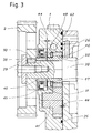
- FIG. 3 which is an enlargement of a part of FIG. 2, makes it possible to better understand the embodiment of the invention at the level of the pump itself.
- the reference 40 designates the drive pinion of the gear pump and the reference 41 designates the idler gear.
- the part 43 is a collar ring, engaged on the camshaft 20, between the flywheel 2 and the pinion 40, the lip seal 45 bearing on said collar ring.
- the pinion 40 is itself supported on the annular shoulder 50 of the camshaft.
- the planar washer 47 is positioned between the internal face of the drive pinion 40 and a shoulder 49 of the pump block. In this shoulder also appears in dotted lines a breather 51 connecting the space where the seal 45 is located and the suction side of the pump.
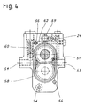
- Figure 4 shows the inlet ports 53 and outlet 54 of the oil; the holes 56 are intended for the guide pins and the holes 24 for the assembly screws 3; the grooves 58 and 59 are intended to receive the seals between the body of the pump 1 and, on the one hand the cylinder head 5, on the other hand the oil distribution member 22 on the bearings of the camshaft.
- Reference 60 designates the safety valve assembly.
- the return duct 62 of the safety valve also appears in section in FIGS. 2 and 3.
- the seal between the pump body and the cylinder head is ensured by the O-ring 25, housed in the groove 58, and kept in pressure by means of the screws 3. It therefore appears, once the drive wheel 2 removed, that the simple unscrewing of the screws 3 allows both to remove and disassemble the pump for its maintenance.
- the O-ring 26, housed in the groove 59 makes it possible to hermetically seal the orifice of the duct of the oil distribution member 22, said orifice resulting from the imperatives of machining.
Landscapes
- Engineering & Computer Science (AREA)
- Mechanical Engineering (AREA)
- General Engineering & Computer Science (AREA)
- Lubrication Of Internal Combustion Engines (AREA)
- Valve-Gear Or Valve Arrangements (AREA)
- Rotary Pumps (AREA)
- Lubrication Details And Ventilation Of Internal Combustion Engines (AREA)
- Cylinder Crankcases Of Internal Combustion Engines (AREA)
Description
- La présente invention a pour objet un moteur à combustion interne, dont la disposition particulière de la pompe de pression du type à engrenages à pignons tangentiels, pour le circulation de l'huile dans les différents organes, permet de diminuer l'encombrement et le poids dudit moteur, ainsi que son coût d'entretien, par exemple lors des démontages.
- Dans les moteurs usuels la pompe de pression servant à faire circuler l'huile dans les différents organes à graisser, est constituée par un ensemble mécanique autonome à carter fermé, entraîné soit directement par le vilebrequin, soit indirectement par ce dernier, par des moyens appropriés, tels que des engrenages ou une courroie crantée.
- Le document EP-A-0 517 014, bénéficiant d'une date antérieure mais publié postérieurement au dépôt de la présente demande, décrit une pompe de pression à engrenages, entraînée directement par un arbre à came. Il est toutefois à noter qu'il s'agit d'une pompe à engrenages à pignons concentriques logés dans un carter ouvert des deux côtés, le côté intérieur étant obturé par le carter moteur, et le côté extérieur étant obturé par l'action conjointe d'un joint placé entre un volant et le carter de la pompe et d'une rondelle d'étanchéité maintenue par des moyens élastiques en appui contre les passages de circulation d'huile.
- Le moteur selon l'invention possède au contraire une pompe de pression pour la circulation de l'huile à carter ouvert d'un seul côté, obturé par fixation directe sur la culasse, les organes mobiles de la pompe étant directement entraînés par l'arbre à cames, auquel ils sont assujettis au moyen d'une butée axiale. Selon l'invention, l'étanchéité entre la culasse et le corps de la pompe est assurée par des joints toriques et des joints à lèvre, et le jeu axial est ajusté au moyen d'une rondelle planée, disposée entre un épaulement annulaire du corps de pompe et la face interne correspondante de l'organe mobile de la pompe entrainé par l'arbre à cames.
- Afin de mieux comprendre l'invention, et d'en faire apparaître plus clairement d'autres buts caractéristiques, détails et avantages, la description détaillée ci-après concerne un mode de réalisation d'un moteur équipé d'une pompe à engrenages.
- Aux dessins annexés :
- la figure 1 est une vue de face du moteur complet avec la pompe de pression;
- la figure 2 est une coupe partielle agrandie selon la ligne II-II de la figure 1, avec représentation de l'arbre à cames et du circuit de distribution d'huile sur les paliers;
- la figure 3 est une vue agrandie de la figure 2, limitée à la partie concernant la pompe;
- la figure 4 est une vue de côté de la pompe, séparée de la culasse, selon la flèche IV de la figure II.
- Dans la figure 1, il apparaît que la pompe 1, partiellement masquée par le volant d'entraînement 2 de l'arbre à cames, est fixée par les vis 3 sur la culasse 5 du moteur. Sur cette figure sont également représentés les conduits d'arrivée 6 et de sortie 7 de l'huile de la pompe ainsi que le conduit d'arrivée 8 de l'huile dans l'organe de distribution 22 sur les paliers de l'arbre à cames. La poulie 11 constitue uniquement un tenseur pour la courroie venant de la poulie 9 fixée sur le vilebrequin.
- La figure 2, qui représente une vue agrandie de la coupe selon la ligne II-II de la figure 1, montre l'assemblage de l'arbre à câmes 20, situé dans la culasse 5 avec, d'une part l'organe de distribution d'huile 22 sur les paliers, et d'autre part la pompe 1 et le volant d'entraînement 2. Dans le corps de la pompe 1 apparaît en pointillés une des vis de fixation 24 du corps de la pompe sur la culasse. Le joint torique 25 assure l'étanchéité entre le corps de la pompe et la culasse, et le joint 26 entre le corps de la pompe et l'extrémité ouverte de l'organe de distribution d'huile 22 sur les paliers de l'arbre à cames. La rondelle 28 et la vis 29 constituent la butée de l'arbre à cames, celui-ci étant rendu solidaire du volant d'entraînement 2 en rotation par la clavette 30.
- La figure 3, qui est un agrandissement d'une partie de la figure 2, permet de mieux comprendre la réalisation de l'invention au niveau de la pompe elle-même. La référence 40 désigne le pignon d'entraînement de la pompe à engrenages et la référence 41 désigne le pignon fou. La pièce 43 est une bague à collerette, engagée sur l'arbre à cames 20, entre le volant 2 et le pignon 40, le joint à lèvres 45 venant en appui sur ladite bague à collerette. Le pignon 40 est lui-même en appui sur l'épaulement annulaire 50 de l'arbre à cames. La rondelle planée 47 est positionnée entre la face interne du pignon d'entraînement 40 et un épaulement 49 du bloc de pompe. Dans cet épaulement apparait également en pointillés un reniflard 51 reliant l'espace où se situe le joint 45 et le côté aspiration de la pompe.
- Outre les éléments déjà décrits dans les figures précédentes, la figure 4 fait apparaître les orifices d'entrée 53 et de sortie 54 de l'huile; les trous 56 sont destinés aux goupilles de guidage et les trous 24 aux vis d'assemblage 3; les gorges 58 et 59 sont destinées à recevoir les joints d'étanchéité entre le corps de la pompe 1 et, d'une part la culasse 5, d'autre part l'organe de distribution d'huile 22 sur les paliers de l'arbre à cames. La référence 60 désigne l'ensemble soupape de sécurité. Le conduit de retour 62 de la soupape de sécurité apparaît également en coupe dans les figures 2 et 3.
- Pour assurer à la pompe à engrenages du moteur selon l'invention, lorsqu'il est en fonctionnement, à la fois une étanchéité suffisante et le jeu axial nécessaire pour éviter un grippage, il a été nécessaire de concevoir un assemblage particulier des pièces, qui ne serait d'aucune utilité dans les pompes à carter fermé, formant un ensemble mécanique autonome.
- L'étanchéité entre le corps de la pompe et la culasse est assurée par le joint torique 25, logé dans la gorge 58, et maintenu en pression au moyen des vis 3. Il apparait donc, une fois le volant d'entrainement 2 déposé, que le simple dévissage des vis 3 permet à la fois de déposer et de démonter la pompe pour son entretien. Le joint torique 26, logé dans la gorge 59, permet d'obturer hermétiquement l'orifice du conduit de l'organe de distribution d'huile 22, ledit orifice resultant des impératifs de l'usinage.
- L'étanchéité, dans le sens de l'arbre à cames, du côté du volant d'entrainement est assuré d'une part par le joint à lèvres 45 monté en force en appui sur la bague 43, d'autre part par le disque plané 47 qui permet d'ajuster très précisement au minimum nécessaire le jeu 44 devant exister entre les pièces en rotation et le corps de pompe ou la culasse. Pour éviter une accumulation d'huile dans l'espace se trouvant entre le joint à lèvre, le corps de la pompe et la bague à collerette 43 il est en outre prévu d'aspirer ladite huile au moyen d'un reniflard 51 reliant ledit espace et la zone d'arrivée d'huile dans la pompe.
- Pour comprendre le rôle essentiel du disque plané 47, il convient de rappeler qu'une fabrication en série de la culasse ne permet pas d'assurer une précision suffisante pour que l'épaulement annulaire 50 de l'arbre à cames, sur lequel sont bloqués au moyen de la vis 29 le pignon d'entrainement 40 et la bague 43, permette de conserver un jeu axial 44, d'une part entre les pignons 40-41 et la partie de la culasse sur laquelle est fixée la pompe, d'autre part entre la bague 43 et l'épaulement annulaire 49 du corps de la pompe. En l'absence du disque plané 47, c'est-à-dire si l'épaulement annulaire avait une épaisseur supplémentaire correspondant à l'épaisseur du disque 47, le rattrapage du jeu, dû à l'usure de l'épaulement annulaire 49 par le frottement du pignon 40, ne pourrait se faire qu'en rectifiant toute la surface de la pompe en contact avec la culasse et la section annulaire du pignon 40, en contact avec la collerette de la bague 43.
- Selon l'invention, il est au contraire très facile, soit à l'occasion d'entretiens périodiques, soit si une fuite d'huile est décelée, de procéder au démontage de la pompe et au remplacement du disque plané usé par un nouveau disque plané. Il est ainsi possible de maintenir en permanence, et très simplement, un jeu axial 44 constant à la valeur désirée, par exemple un jeu de 50µm.
- Grâce à cette conception et à cette disposition particulière de la pompe, il est ainsi possible d'obtenir tous types de moteurs selon l'invention, présentant un encombrement et un poids réduits, et dont l'entretien et la maintenance de la pompe à pression d'huile se trouvent facilités.
Claims (6)
- Moteur à combustion interne possédant un circuit de circulation d'huile comprenant une pompe de pression à engrenages à pignons (40,41) tangentiels, le pignon d'entrainement (40) étant directement assujetti à un arbre à cames (20) par l'intermédiaire d'une bague (43) au moyen d'une butée axiale formée par une rondelle (28) et une vis (29), le corps de pompe (1) à carter ouvert étant obturé par application directe sur la culasse (5) et le jeu axial (44) des pignons (40, 41) étant ajusté au moyen d'une rondelle planée (47)
- Moteur à combustion interne selon la revendication 1, caractérisé en ce que la rondelle planée (47) est intercalée entre un épaulement annulaire (49) du corps de pompe (1) et la face correspondante du pignon d'entrainement (40) de la pompe.
- Moteur à combustion interne selon la revendication 1, caractérisé en ce que la bague (43) est disposée entre le pignon d'entrainement (40), en appui sur un épaulement annulaire (50) de l'arbre à cames (20) et un volant (2).
- Moteur à combustion interne selon la revendication 1, caractérisé en ce que l'étanchéité entre le corps de pompe (1) et la culasse (5) est assurée par un joint torique (25)
- Moteur à combustion interne selon la revendication 1, caractérisé en ce que l'étanchéité entre le corps de pompe (1) et l'arbre à cames (20), du côté extérieur de la pompe, est assurée au moyen d'un joint à lèvres (45) et d'un reniflard (51).
- Moteur à combustion interne selon la revendication 5, caractérisé en ce que le reniflard (51) est relié au côté aspirant de la pompe.
Applications Claiming Priority (2)
| Application Number | Priority Date | Filing Date | Title |
|---|---|---|---|
| FR9113769A FR2683262B1 (fr) | 1991-11-06 | 1991-11-06 | Moteur a combustion interne avec pompe a huile sur l'arbre a cames. |
| FR9113769 | 1991-11-06 |
Publications (2)
| Publication Number | Publication Date |
|---|---|
| EP0540977A1 EP0540977A1 (fr) | 1993-05-12 |
| EP0540977B1 true EP0540977B1 (fr) | 1995-09-13 |
Family
ID=9418733
Family Applications (1)
| Application Number | Title | Priority Date | Filing Date |
|---|---|---|---|
| EP92118294A Expired - Lifetime EP0540977B1 (fr) | 1991-11-06 | 1992-10-26 | Moteur à combustion interne avec pompe à huile sur l'arbre à cames |
Country Status (21)
| Country | Link |
|---|---|
| US (1) | US5295463A (fr) |
| EP (1) | EP0540977B1 (fr) |
| JP (1) | JP3316006B2 (fr) |
| KR (1) | KR100296020B1 (fr) |
| CN (1) | CN1040036C (fr) |
| AR (1) | AR248177A1 (fr) |
| AT (1) | ATE127880T1 (fr) |
| AU (1) | AU655387B2 (fr) |
| BR (1) | BR9204239A (fr) |
| CA (1) | CA2082207C (fr) |
| CZ (1) | CZ329192A3 (fr) |
| DE (1) | DE69204798T2 (fr) |
| ES (1) | ES2081026T3 (fr) |
| FR (1) | FR2683262B1 (fr) |
| HU (1) | HU217855B (fr) |
| IL (1) | IL103423A (fr) |
| PL (1) | PL169445B1 (fr) |
| RU (1) | RU2055220C1 (fr) |
| SK (1) | SK329192A3 (fr) |
| TW (1) | TW203112B (fr) |
| ZA (1) | ZA927879B (fr) |
Families Citing this family (15)
| Publication number | Priority date | Publication date | Assignee | Title |
|---|---|---|---|---|
| DE4424248C1 (de) * | 1994-07-09 | 1995-12-07 | Porsche Ag | Brennkraftmaschine mit zwei gegen die Vertikale geneigten Zylinderbänken |
| DE19624240C5 (de) * | 1996-06-18 | 2011-07-28 | Daimler AG, 70327 | Brennkraftmaschine |
| EP0966597A1 (fr) * | 1998-01-15 | 1999-12-29 | Stanadyne Automotive Corp. | Pompe hydraulique a palier d'entrainement monte sur un moteur |
| DE69913256T2 (de) * | 1998-05-11 | 2004-05-27 | Yamaha Hatsudoki K.K., Iwata | Brennkraftmaschine |
| US6047667A (en) * | 1998-07-24 | 2000-04-11 | Harley-Davidson Motor Company | Motorcycle camshaft support plate |
| US7174998B2 (en) * | 2001-10-15 | 2007-02-13 | Borgwarner Inc. | Submerged electric fluid pump |
| US7219645B2 (en) * | 2005-07-01 | 2007-05-22 | Harley-Davidson Motor Company Group, Inc. | Oil pump for a motorcycle |
| US7171939B1 (en) | 2005-09-30 | 2007-02-06 | S&S Cycle, Inc. | Integrated cam drive and oil pump assembly for motorcycle engines and the like |
| USD544509S1 (en) | 2005-09-30 | 2007-06-12 | S&S Cycle, Inc. | Gear cover |
| DE102007012704A1 (de) * | 2007-03-16 | 2008-09-18 | Robert Bosch Gmbh | Hochdruckpumpe zur Förderung von Kraftstoff mit einer verbesserten Ausbildung der Lageranordnung zur Lagerung der Nockenwelle |
| JP4247644B2 (ja) * | 2007-06-29 | 2009-04-02 | 三菱自動車工業株式会社 | 内燃機関の可変動弁装置 |
| DE102008007285A1 (de) * | 2008-02-02 | 2009-08-06 | Bayerische Motoren Werke Aktiengesellschaft | Nockenwellengetriebene Pumpe für eine Kraftfahrzeug-Brennkraftmaschine und Kraftfahrzeug-Brennkraftmaschine |
| DE102009016048B4 (de) * | 2009-04-02 | 2018-05-30 | Bayerische Motoren Werke Aktiengesellschaft | Pumpe für eine Kraftfahrzeug-Brennkraftmaschine sowie Kraftfahrzeug-Brennkraftmaschine mit Pumpe |
| JP2010285884A (ja) * | 2009-06-09 | 2010-12-24 | Fuji Heavy Ind Ltd | エンジンの潤滑装置 |
| RU2539233C2 (ru) * | 2013-01-10 | 2015-01-20 | Открытое акционерное общество "Автодизель" (Ярославский моторный завод) | Двигатель внутреннего сгорания |
Citations (1)
| Publication number | Priority date | Publication date | Assignee | Title |
|---|---|---|---|---|
| EP0517014A1 (fr) * | 1991-06-07 | 1992-12-09 | Schwäbische Hüttenwerke Gesellschaft mit beschränkter Haftung | Pompe à engrenages pour huile de lubrification d'un moteur à combustion interne, en particulier pour véhicules |
Family Cites Families (8)
| Publication number | Priority date | Publication date | Assignee | Title |
|---|---|---|---|---|
| US3087582A (en) * | 1961-07-10 | 1963-04-30 | American Motors Corp | Engine lubricating apparatus |
| GB1365805A (en) * | 1972-02-11 | 1974-09-04 | Cunewalde Motoren | Internal combustion engines |
| US4573439A (en) * | 1979-12-18 | 1986-03-04 | Cummins Engine Company, Inc. | Oil pump arrangement for supplying oil under pressure in an internal combustion engine |
| DE3044253A1 (de) * | 1980-11-25 | 1982-06-24 | Bayerische Motoren Werke AG, 8000 München | Brennkraftmaschine, insbesondere einreihige mehrzylinder-brennkraftmaschine |
| FR2540553A1 (fr) * | 1983-02-03 | 1984-08-10 | Renault | Dispositif de commande a came, notamment pour soupapes de moteurs a combustion interne |
| AT389739B (de) * | 1984-09-21 | 1990-01-25 | Avl Verbrennungskraft Messtech | Viertakt-brennkraftmaschine mit einer als zahnradpumpe ausgebildeten schmieroelpumpe |
| IT1180140B (it) * | 1984-11-19 | 1987-09-23 | Tecnamotor Spa | Albero di distribuzione composito per motori endotermici |
| FR2607867B1 (fr) * | 1986-12-08 | 1991-01-11 | Peugeot | Dispositif assurant la circulation d'un lubrifiant dans un circuit de lubrification d'un moteur a combustion interne |
-
1991
- 1991-11-06 FR FR9113769A patent/FR2683262B1/fr not_active Expired - Fee Related
-
1992
- 1992-10-13 ZA ZA927879A patent/ZA927879B/xx unknown
- 1992-10-14 IL IL10342392A patent/IL103423A/en not_active IP Right Cessation
- 1992-10-26 DE DE69204798T patent/DE69204798T2/de not_active Expired - Fee Related
- 1992-10-26 EP EP92118294A patent/EP0540977B1/fr not_active Expired - Lifetime
- 1992-10-26 AT AT92118294T patent/ATE127880T1/de not_active IP Right Cessation
- 1992-10-26 ES ES92118294T patent/ES2081026T3/es not_active Expired - Lifetime
- 1992-10-27 HU HU9203373A patent/HU217855B/hu not_active IP Right Cessation
- 1992-10-27 KR KR1019920019781A patent/KR100296020B1/ko not_active Expired - Fee Related
- 1992-10-29 JP JP29133592A patent/JP3316006B2/ja not_active Expired - Fee Related
- 1992-10-30 BR BR929204239A patent/BR9204239A/pt not_active IP Right Cessation
- 1992-11-02 SK SK3291-92A patent/SK329192A3/sk unknown
- 1992-11-02 CZ CS923291A patent/CZ329192A3/cs unknown
- 1992-11-04 PL PL92296470A patent/PL169445B1/pl unknown
- 1992-11-05 AU AU28159/92A patent/AU655387B2/en not_active Ceased
- 1992-11-05 CA CA002082207A patent/CA2082207C/fr not_active Expired - Fee Related
- 1992-11-05 RU RU9292004383A patent/RU2055220C1/ru active
- 1992-11-05 CN CN92112895A patent/CN1040036C/zh not_active Expired - Fee Related
- 1992-11-05 AR AR92323594A patent/AR248177A1/es active
- 1992-11-06 US US07/973,817 patent/US5295463A/en not_active Expired - Fee Related
- 1992-11-10 TW TW081109061A patent/TW203112B/zh active
Patent Citations (1)
| Publication number | Priority date | Publication date | Assignee | Title |
|---|---|---|---|---|
| EP0517014A1 (fr) * | 1991-06-07 | 1992-12-09 | Schwäbische Hüttenwerke Gesellschaft mit beschränkter Haftung | Pompe à engrenages pour huile de lubrification d'un moteur à combustion interne, en particulier pour véhicules |
Also Published As
| Publication number | Publication date |
|---|---|
| CA2082207C (fr) | 2002-09-17 |
| AU655387B2 (en) | 1994-12-15 |
| CN1075773A (zh) | 1993-09-01 |
| PL296470A1 (en) | 1993-07-12 |
| KR930010352A (ko) | 1993-06-22 |
| HU9203373D0 (en) | 1993-03-01 |
| RU2055220C1 (ru) | 1996-02-27 |
| ES2081026T3 (es) | 1996-02-16 |
| BR9204239A (pt) | 1993-05-11 |
| FR2683262B1 (fr) | 1995-02-03 |
| JP3316006B2 (ja) | 2002-08-19 |
| TW203112B (fr) | 1993-04-01 |
| HUT63484A (en) | 1993-08-30 |
| FR2683262A1 (fr) | 1993-05-07 |
| CN1040036C (zh) | 1998-09-30 |
| PL169445B1 (pl) | 1996-07-31 |
| JPH05214916A (ja) | 1993-08-24 |
| KR100296020B1 (ko) | 2001-11-22 |
| HU217855B (hu) | 2000-04-28 |
| SK329192A3 (en) | 1995-05-10 |
| ATE127880T1 (de) | 1995-09-15 |
| DE69204798D1 (de) | 1995-10-19 |
| AU2815992A (en) | 1993-05-13 |
| DE69204798T2 (de) | 1996-05-02 |
| IL103423A0 (en) | 1993-03-15 |
| AR248177A1 (es) | 1995-06-30 |
| EP0540977A1 (fr) | 1993-05-12 |
| IL103423A (en) | 1995-07-31 |
| ZA927879B (en) | 1993-04-21 |
| CA2082207A1 (fr) | 1993-05-07 |
| CZ329192A3 (en) | 1993-05-12 |
| US5295463A (en) | 1994-03-22 |
Similar Documents
| Publication | Publication Date | Title |
|---|---|---|
| EP0540977A1 (fr) | Moteur à combustion interne avec pompe à huile sur l'arbre à cames | |
| EP4023909B1 (fr) | Porte-satellites pour un reducteur mecanique de turbomachine d aeronef | |
| FR3022300A1 (fr) | Dispositif de lubrification pour une turbomachine | |
| CN209557101U (zh) | 可变压缩比机构 | |
| FR2556775A1 (fr) | Dispositif de limitation de la pression dans un circuit de lubrification de moteur | |
| EP0271384B1 (fr) | Dispositif assurant la circulation d'un lubrifiant dans un circuit de lubrification d'un moteur à combustion interne | |
| US4116588A (en) | Fluid pump | |
| CN100389284C (zh) | 一种内燃机机油泵 | |
| FR2509802A1 (fr) | Pompes et moteurs | |
| FR2657920A1 (fr) | Moteur a combustion interne a piston rotatif. | |
| JP2004225702A (ja) | オイルモジュール | |
| FR2482208A1 (fr) | ||
| JPS6221687Y2 (fr) | ||
| FR2478221A1 (fr) | Machine a engrenage, telle que pompe ou moteur hydraulique | |
| JPS61135993A (ja) | 回転式歯車ポンプ | |
| FR2657919A1 (fr) | Moteur a combustion interne a piston rotatif. | |
| KR19990007248A (ko) | 유압 펌프 | |
| EP1567751A1 (fr) | Dispositif d'accouplement d'un organe rotatif a un arbre a cames | |
| JPH11294691A (ja) | ポンプ装置 | |
| FR3077610A1 (fr) | Assemblage etancheifie d'une portion d'extremite de vilebrequin avec un volant d'inertie et un palier de guidage, et ensemble moteur associe | |
| KR100610072B1 (ko) | 자동변속기의 오일펌프 | |
| EP0597743B1 (fr) | Agencement d'une pompe à huile de lubrification d'un moteur à combustion | |
| JP2508022B2 (ja) | 点火配電器のオイルシ−ルの潤滑機構 | |
| TW202513969A (zh) | 泵浦 | |
| FR3162795A1 (fr) | Boitier d’accessoires pour une turbomachine d’aeronef |
Legal Events
| Date | Code | Title | Description |
|---|---|---|---|
| PUAI | Public reference made under article 153(3) epc to a published international application that has entered the european phase |
Free format text: ORIGINAL CODE: 0009012 |
|
| AK | Designated contracting states |
Kind code of ref document: A1 Designated state(s): AT BE CH DE DK ES GB GR IE IT LI LU NL PT SE |
|
| 17P | Request for examination filed |
Effective date: 19930614 |
|
| 17Q | First examination report despatched |
Effective date: 19940712 |
|
| GRAA | (expected) grant |
Free format text: ORIGINAL CODE: 0009210 |
|
| AK | Designated contracting states |
Kind code of ref document: B1 Designated state(s): AT BE CH DE DK ES GB GR IE IT LI LU NL PT SE |
|
| PG25 | Lapsed in a contracting state [announced via postgrant information from national office to epo] |
Ref country code: DK Effective date: 19950913 Ref country code: GR Free format text: LAPSE BECAUSE OF FAILURE TO SUBMIT A TRANSLATION OF THE DESCRIPTION OR TO PAY THE FEE WITHIN THE PRESCRIBED TIME-LIMIT Effective date: 19950913 |
|
| REF | Corresponds to: |
Ref document number: 127880 Country of ref document: AT Date of ref document: 19950915 Kind code of ref document: T |
|
| REG | Reference to a national code |
Ref country code: IE Ref legal event code: FG4D Free format text: 65220 |
|
| REF | Corresponds to: |
Ref document number: 69204798 Country of ref document: DE Date of ref document: 19951019 |
|
| ITF | It: translation for a ep patent filed | ||
| PG25 | Lapsed in a contracting state [announced via postgrant information from national office to epo] |
Ref country code: PT Effective date: 19951213 |
|
| GBT | Gb: translation of ep patent filed (gb section 77(6)(a)/1977) |
Effective date: 19951128 |
|
| REG | Reference to a national code |
Ref country code: ES Ref legal event code: FG2A Ref document number: 2081026 Country of ref document: ES Kind code of ref document: T3 |
|
| PG25 | Lapsed in a contracting state [announced via postgrant information from national office to epo] |
Ref country code: IE Free format text: LAPSE BECAUSE OF NON-PAYMENT OF DUE FEES Effective date: 19960402 |
|
| REG | Reference to a national code |
Ref country code: IE Ref legal event code: FD4D Ref document number: 65220 Country of ref document: IE |
|
| PLBE | No opposition filed within time limit |
Free format text: ORIGINAL CODE: 0009261 |
|
| STAA | Information on the status of an ep patent application or granted ep patent |
Free format text: STATUS: NO OPPOSITION FILED WITHIN TIME LIMIT |
|
| 26N | No opposition filed | ||
| PGFP | Annual fee paid to national office [announced via postgrant information from national office to epo] |
Ref country code: LU Payment date: 20000929 Year of fee payment: 9 |
|
| PGFP | Annual fee paid to national office [announced via postgrant information from national office to epo] |
Ref country code: NL Payment date: 20000930 Year of fee payment: 9 |
|
| PG25 | Lapsed in a contracting state [announced via postgrant information from national office to epo] |
Ref country code: LU Free format text: LAPSE BECAUSE OF NON-PAYMENT OF DUE FEES Effective date: 20011026 |
|
| REG | Reference to a national code |
Ref country code: GB Ref legal event code: IF02 |
|
| PG25 | Lapsed in a contracting state [announced via postgrant information from national office to epo] |
Ref country code: NL Free format text: LAPSE BECAUSE OF NON-PAYMENT OF DUE FEES Effective date: 20020501 |
|
| NLV4 | Nl: lapsed or anulled due to non-payment of the annual fee |
Effective date: 20020501 |
|
| PGFP | Annual fee paid to national office [announced via postgrant information from national office to epo] |
Ref country code: AT Payment date: 20030922 Year of fee payment: 12 |
|
| PGFP | Annual fee paid to national office [announced via postgrant information from national office to epo] |
Ref country code: SE Payment date: 20030925 Year of fee payment: 12 |
|
| PGFP | Annual fee paid to national office [announced via postgrant information from national office to epo] |
Ref country code: CH Payment date: 20030926 Year of fee payment: 12 |
|
| PGFP | Annual fee paid to national office [announced via postgrant information from national office to epo] |
Ref country code: GB Payment date: 20030929 Year of fee payment: 12 |
|
| PGFP | Annual fee paid to national office [announced via postgrant information from national office to epo] |
Ref country code: DE Payment date: 20030930 Year of fee payment: 12 |
|
| PGFP | Annual fee paid to national office [announced via postgrant information from national office to epo] |
Ref country code: ES Payment date: 20031010 Year of fee payment: 12 |
|
| PGFP | Annual fee paid to national office [announced via postgrant information from national office to epo] |
Ref country code: BE Payment date: 20040924 Year of fee payment: 13 |
|
| PG25 | Lapsed in a contracting state [announced via postgrant information from national office to epo] |
Ref country code: GB Free format text: LAPSE BECAUSE OF NON-PAYMENT OF DUE FEES Effective date: 20041026 Ref country code: AT Free format text: LAPSE BECAUSE OF NON-PAYMENT OF DUE FEES Effective date: 20041026 |
|
| PG25 | Lapsed in a contracting state [announced via postgrant information from national office to epo] |
Ref country code: SE Free format text: LAPSE BECAUSE OF NON-PAYMENT OF DUE FEES Effective date: 20041027 Ref country code: ES Free format text: LAPSE BECAUSE OF NON-PAYMENT OF DUE FEES Effective date: 20041027 |
|
| PG25 | Lapsed in a contracting state [announced via postgrant information from national office to epo] |
Ref country code: CH Free format text: LAPSE BECAUSE OF NON-PAYMENT OF DUE FEES Effective date: 20041031 Ref country code: LI Free format text: LAPSE BECAUSE OF NON-PAYMENT OF DUE FEES Effective date: 20041031 |
|
| PG25 | Lapsed in a contracting state [announced via postgrant information from national office to epo] |
Ref country code: DE Free format text: LAPSE BECAUSE OF NON-PAYMENT OF DUE FEES Effective date: 20050503 |
|
| EUG | Se: european patent has lapsed | ||
| GBPC | Gb: european patent ceased through non-payment of renewal fee |
Effective date: 20041026 |
|
| REG | Reference to a national code |
Ref country code: CH Ref legal event code: PL |
|
| PG25 | Lapsed in a contracting state [announced via postgrant information from national office to epo] |
Ref country code: IT Free format text: LAPSE BECAUSE OF NON-PAYMENT OF DUE FEES;WARNING: LAPSES OF ITALIAN PATENTS WITH EFFECTIVE DATE BEFORE 2007 MAY HAVE OCCURRED AT ANY TIME BEFORE 2007. THE CORRECT EFFECTIVE DATE MAY BE DIFFERENT FROM THE ONE RECORDED. Effective date: 20051026 |
|
| PG25 | Lapsed in a contracting state [announced via postgrant information from national office to epo] |
Ref country code: BE Free format text: LAPSE BECAUSE OF NON-PAYMENT OF DUE FEES Effective date: 20051031 |
|
| REG | Reference to a national code |
Ref country code: ES Ref legal event code: FD2A Effective date: 20041027 |
|
| BERE | Be: lapsed |
Owner name: *SMH MANAGEMENT SERVICES A.G. Effective date: 20051031 |