EP0541285A2 - Fixiervorrichtung für Kopiergeräte - Google Patents
Fixiervorrichtung für Kopiergeräte Download PDFInfo
- Publication number
- EP0541285A2 EP0541285A2 EP92309837A EP92309837A EP0541285A2 EP 0541285 A2 EP0541285 A2 EP 0541285A2 EP 92309837 A EP92309837 A EP 92309837A EP 92309837 A EP92309837 A EP 92309837A EP 0541285 A2 EP0541285 A2 EP 0541285A2
- Authority
- EP
- European Patent Office
- Prior art keywords
- fixing device
- shoulder
- heating element
- heat
- pressure roll
- Prior art date
- Legal status (The legal status is an assumption and is not a legal conclusion. Google has not performed a legal analysis and makes no representation as to the accuracy of the status listed.)
- Granted
Links
Images

Classifications
-
- G—PHYSICS
- G03—PHOTOGRAPHY; CINEMATOGRAPHY; ANALOGOUS TECHNIQUES USING WAVES OTHER THAN OPTICAL WAVES; ELECTROGRAPHY; HOLOGRAPHY
- G03G—ELECTROGRAPHY; ELECTROPHOTOGRAPHY; MAGNETOGRAPHY
- G03G15/00—Apparatus for electrographic processes using a charge pattern
- G03G15/20—Apparatus for electrographic processes using a charge pattern for fixing, e.g. by using heat
- G03G15/2003—Apparatus for electrographic processes using a charge pattern for fixing, e.g. by using heat using heat
- G03G15/2014—Apparatus for electrographic processes using a charge pattern for fixing, e.g. by using heat using heat using contact heat
- G03G15/2064—Apparatus for electrographic processes using a charge pattern for fixing, e.g. by using heat using heat using contact heat combined with pressure
Definitions
- the present invention relates to a fixing device for copying machines for indelibly fixing an image developed by means of toner powder onto a sheet of paper or similar information supports and more particularly to a device for eliminating the spontaneous curling of sheets and for improving the fixing of an image on sheets or information supports.
- a straight heating element is arranged perpendicularly to the forwarding direction of the sheets of paper or information supports and is fixed on a heat refractory support.
- a belt-type transport element is positioned between the heating element and the face of the sheet of paper or information support on which a toner powder image has been deposited and a pressure roll is pressed against the back of the information support. The heat and pressure fix the toner powder image to the sheet of paper or information support.
- a preferred embodiment of the present invention provides a fixing device for a copying machine in which a linear heating element is positioned transversely to the direction of movement of sheets in the copying machine. This heating element is immediately followed by a shoulder projecting beyond the heating element and over which sheets must pass as they emerge from the fixing device. This shoulder gives the sheets an opposite curl to that which they would adopt as a result of the heating of one face. Thus sheets emerge having retained their original flat form.
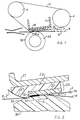
- an endless belt-type transport element 2 passes around two forwarding rolls 4 and 6.
- the belt 2 preferably consists of a thin sheet of Mylar (registered trade mark) some 75 ⁇ m thick, driven in the direction F by the drive roll 4, to forward a sheet 8 on whose upper face 10 a toner powder image 12 is deposited which must be fixed by heat and pressure to the sheet 8.
- a heating element 15 is fixed to an underside of a support 17 located inside the belt 2.
- the heating element 15 consists of a strip of resistive material 1.5-3 mm wide measured in the forwarding direction of the belt 2.
- the length of the element 15, measured perpendicularly to the forwarding direction is generally greater than the maximum format of sheets handled by the copier.
- the element 15 (fig. 2) is deposited by a screen printing process on an alumina plate 20 approximately 1-2 mm thick which in turn is embedded in a base 22 of a heat-resistant resin such as PEEK (Polyetherether-ketone) or LCPs (liquid-crystal polymers).
- PEEK Polyetherether-ketone
- LCPs liquid-crystal polymers
- the resin forming the base 22 must retain its physical and mechanical characteristics unaltered up to a temperature of at least 280°C and in particular at this temperature must retain high resistance to wear and to concentrated loads.
- the block 24 is fixed in some suitable manner to the metal support 17 forming part of the frame of the copier.
- a pressure roll 30 is kept pressed against the belt 2 to keep it in contact with the block 24, with a total load of about 8 kg.
- the roll 30 comprises an outer layer 32 of soft heat-resistant rubber which adheres to the outer surface 34 of the belt 2 over a contact area or strip S whose width is between 4 and 6 MM.
- the width of the strip S is measured in the forwarding direction of the belt 2 indicated by F.
- the base 22 projects beyond the plate 20 in the direction of movement of the belt 2, with a curved profile 21 whose generous curvature is in the opposite direction to the curvature of the roll 30, hence moving away from the outer surface 31 of the roll 30.
- the profile 21 accompanies the belt 2 in its movement towards the roll 6.
- the heat transmitted by the element 15 through the belt 2 softens the toner powder which sticks to the sheet 8.
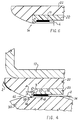
- the resin base 22 is constructed so as to comprise a shoulder 36 (Fig. 4) which projects towards the roll 30 away from the surface of contact 34 between the roll 30 and the belt 2.
- the shoulder 36 is located immediately beyond the leaving edge 37 of the element 15 in the direction F at a distance "b" typically in the range 0 to 2.5 mm, and preferably between 0.1 and 0.3 mm.
- the shoulder 36 is manufactured to a curved surface having a curved profile 38 whose radius of curvature R is typically between 0.1 and 0.3 mm and preferably equal to 0.2 mm and extends perpendicularly to the plane of the figures over a length equal to the length of the element 15.
- the shoulder 36 projects away from the surface 34 by a good amount "d”, typically 0.1 - 0.3 mm, and preferably equal to 0.2 mm.
- the length of the shoulder 36 is greater than the width of a sheet of the maximum format that can be used through the fixing device 2, 15, 30.
- the roll 30 is positioned relative to the block 24 (Fig. 2) such that the area of contact S completely covers the shoulder 36 and extends beyond it by an amount "a" (Fig. 4) of length typically in the range 0.5 - 1.5 mm.
- the compression of the rubber layer 32 of the roll 30 forces the belt 2 to adhere along the profile 38 of the shoulder 36.
- a sheet is passing through the fixing device it is pressed between the roll 30 and the belt 2 in the contact area S and is therefore forced to curve in the direction of the curvature of the profile 38 of the shoulder 36.
- the heating element is located close to the leaving edge 40 of the plate 22 in the forwarding direction of the belt 2 indicated by F.
- the base 22 may alternatively be made from a good heat-conducting metal such as aluminium, copper, bronze or titanium.
- the projection 36 may also be protected by covering it with a thin protective layer of, for example, teflon (TM) or a ceramic material.
- TM teflon
- the projection 36 may also be made by using (Fig. 5) a metal element 45 inserted between the plate 20 and the base 22.
- the element 45 is approximately 0.2 mm thick and ends in a bottom edge 47 having a curved profile 48 whose radius of curvature is between 0.1 and 0.3 mm and preferably equal to 0.2 mm.
- the element 45 will appropriately be made of aluminium and the edge 47 may be covered by a thin protective layer of ceramic material.
- the edge 47 of the element 45 must project from the lower surface 49 of the belt 2 by an amount "E" of approximately 0.1 - 0.2 mm, preferably equal to 0.2 mm.
Landscapes
- Physics & Mathematics (AREA)
- General Physics & Mathematics (AREA)
- Fixing For Electrophotography (AREA)
- Separation, Sorting, Adjustment, Or Bending Of Sheets To Be Conveyed (AREA)
Applications Claiming Priority (2)
| Application Number | Priority Date | Filing Date | Title |
|---|---|---|---|
| ITTO910832 | 1991-11-05 | ||
| ITTO910832A IT1250851B (it) | 1991-11-05 | 1991-11-05 | Dispositivo di fissaggio per copiatrici. |
Publications (3)
| Publication Number | Publication Date |
|---|---|
| EP0541285A2 true EP0541285A2 (de) | 1993-05-12 |
| EP0541285A3 EP0541285A3 (en) | 1993-06-16 |
| EP0541285B1 EP0541285B1 (de) | 1996-09-25 |
Family
ID=11409685
Family Applications (1)
| Application Number | Title | Priority Date | Filing Date |
|---|---|---|---|
| EP92309837A Expired - Lifetime EP0541285B1 (de) | 1991-11-05 | 1992-10-27 | Fixiervorrichtung für Kopiergeräte |
Country Status (5)
| Country | Link |
|---|---|
| US (1) | US5319425A (de) |
| EP (1) | EP0541285B1 (de) |
| JP (1) | JPH05257402A (de) |
| DE (1) | DE69214089T2 (de) |
| IT (1) | IT1250851B (de) |
Families Citing this family (6)
| Publication number | Priority date | Publication date | Assignee | Title |
|---|---|---|---|---|
| US6947699B2 (en) * | 2002-02-05 | 2005-09-20 | Canon Kabushiki Kaisha | Image heating apparatus with projection extending in longitudinal direction of supporting member |
| US7010256B2 (en) * | 2002-11-14 | 2006-03-07 | Canon Kabushiki Kaisha | Image heating apparatus having recording medium conveying nip nonuniform in pressure distribution |
| JP4612812B2 (ja) | 2003-07-11 | 2011-01-12 | キヤノン株式会社 | 定着装置 |
| US20120003346A1 (en) * | 2010-06-30 | 2012-01-05 | Canon Kabushiki Kaisha | Sheet surface treating apparatus |
| JP6476620B2 (ja) * | 2013-08-26 | 2019-03-06 | 株式会社リコー | 定着装置及び画像形成装置 |
| JP2019168593A (ja) * | 2018-03-23 | 2019-10-03 | コニカミノルタ株式会社 | 定着装置 |
Family Cites Families (6)
| Publication number | Priority date | Publication date | Assignee | Title |
|---|---|---|---|---|
| US5162634A (en) * | 1988-11-15 | 1992-11-10 | Canon Kabushiki Kaisha | Image fixing apparatus |
| JPH0823723B2 (ja) * | 1989-03-28 | 1996-03-06 | キヤノン株式会社 | 定着装置 |
| EP0443799B1 (de) * | 1990-02-20 | 1995-08-16 | Canon Kabushiki Kaisha | Bild-Heizgerät mit von einem rotierenden Element angetriebenen Film |
| US5148226A (en) * | 1990-06-11 | 1992-09-15 | Canon Kabushiki Kaisha | Heating apparatus using endless film |
| EP0461596B1 (de) * | 1990-06-11 | 1997-09-03 | Canon Kabushiki Kaisha | Heizgerät mit Endlosfilm |
| JP2941962B2 (ja) * | 1991-01-08 | 1999-08-30 | キヤノン株式会社 | 定着装置 |
-
1991
- 1991-11-05 IT ITTO910832A patent/IT1250851B/it active IP Right Grant
-
1992
- 1992-10-27 DE DE69214089T patent/DE69214089T2/de not_active Expired - Lifetime
- 1992-10-27 EP EP92309837A patent/EP0541285B1/de not_active Expired - Lifetime
- 1992-10-29 JP JP4291141A patent/JPH05257402A/ja not_active Withdrawn
- 1992-11-04 US US07/971,231 patent/US5319425A/en not_active Expired - Lifetime
Also Published As
| Publication number | Publication date |
|---|---|
| JPH05257402A (ja) | 1993-10-08 |
| US5319425A (en) | 1994-06-07 |
| ITTO910832A1 (it) | 1993-05-05 |
| IT1250851B (it) | 1995-04-21 |
| DE69214089D1 (de) | 1996-10-31 |
| ITTO910832A0 (it) | 1991-11-05 |
| EP0541285A3 (en) | 1993-06-16 |
| DE69214089T2 (de) | 1997-04-30 |
| EP0541285B1 (de) | 1996-09-25 |
Similar Documents
| Publication | Publication Date | Title |
|---|---|---|
| EP0485123B1 (de) | Vorrichtung zur Beseitigung von Blattwellungen | |
| US6236829B1 (en) | Fixing device | |
| EP0494627B1 (de) | Heizgerät | |
| US6795678B2 (en) | Image forming apparatus for fixing a toner image on a sheet or recording medium by use of a belt member | |
| EP0487265A2 (de) | Fixiervorrichtung mit selektierbarem Fertigbearbeitungszustand | |
| JPH0444081A (ja) | 像加熱装置 | |
| EP1176794A3 (de) | Verfahren und Gerät zum Fixieren von Farbtoner mit Hilfe eines blattartig gerformten Druckglieds | |
| JPH0444078A (ja) | 加熱装置 | |
| EP0541285A2 (de) | Fixiervorrichtung für Kopiergeräte | |
| JP4261714B2 (ja) | 定着装置 | |
| EP1343055B1 (de) | Extern beheiztes dickes Schmelzfixierband | |
| KR20020064975A (ko) | 가열 정착 장치 | |
| US5623331A (en) | High-speed electrophotographic fixing unit | |
| EP0345034B1 (de) | Fixiergerät für ein Tonerbild in einer Bilderzeugungsmaschine | |
| DE4315741A1 (de) | Wärmefixiereinrichtung und eine solche Einrichtung verwendendes elektrophotographisches Gerät | |
| JPH0580666A (ja) | ベルト定着装置 | |
| JP2008275753A (ja) | 加熱定着装置 | |
| JP3119002B2 (ja) | 加熱装置 | |
| EP4276542A1 (de) | Fixiervorrichtung und bilderzeugungsvorrichtung | |
| JPH04261567A (ja) | 像加熱装置 | |
| JPH08339131A (ja) | 加熱装置及び画像形成装置 | |
| JP3593207B2 (ja) | 定着装置 | |
| JPH01267255A (ja) | カール矯正装置 | |
| JPH04199170A (ja) | 定着装置 | |
| JPH11305508A (ja) | カール矯正装置 |
Legal Events
| Date | Code | Title | Description |
|---|---|---|---|
| PUAI | Public reference made under article 153(3) epc to a published international application that has entered the european phase |
Free format text: ORIGINAL CODE: 0009012 |
|
| PUAL | Search report despatched |
Free format text: ORIGINAL CODE: 0009013 |
|
| AK | Designated contracting states |
Kind code of ref document: A2 Designated state(s): DE FR GB NL |
|
| AK | Designated contracting states |
Kind code of ref document: A3 Designated state(s): DE FR GB NL |
|
| 17P | Request for examination filed |
Effective date: 19931215 |
|
| 17Q | First examination report despatched |
Effective date: 19950223 |
|
| GRAG | Despatch of communication of intention to grant |
Free format text: ORIGINAL CODE: EPIDOS AGRA |
|
| GRAH | Despatch of communication of intention to grant a patent |
Free format text: ORIGINAL CODE: EPIDOS IGRA |
|
| GRAH | Despatch of communication of intention to grant a patent |
Free format text: ORIGINAL CODE: EPIDOS IGRA |
|
| GRAA | (expected) grant |
Free format text: ORIGINAL CODE: 0009210 |
|
| AK | Designated contracting states |
Kind code of ref document: B1 Designated state(s): DE FR GB NL |
|
| REF | Corresponds to: |
Ref document number: 69214089 Country of ref document: DE Date of ref document: 19961031 |
|
| ET | Fr: translation filed | ||
| PLBE | No opposition filed within time limit |
Free format text: ORIGINAL CODE: 0009261 |
|
| 26N | No opposition filed | ||
| REG | Reference to a national code |
Ref country code: GB Ref legal event code: IF02 |
|
| PGFP | Annual fee paid to national office [announced via postgrant information from national office to epo] |
Ref country code: DE Payment date: 20101027 Year of fee payment: 19 |
|
| PGFP | Annual fee paid to national office [announced via postgrant information from national office to epo] |
Ref country code: GB Payment date: 20101025 Year of fee payment: 19 |
|
| PGFP | Annual fee paid to national office [announced via postgrant information from national office to epo] |
Ref country code: FR Payment date: 20111028 Year of fee payment: 20 Ref country code: NL Payment date: 20111028 Year of fee payment: 20 |
|
| REG | Reference to a national code |
Ref country code: DE Ref legal event code: R071 Ref document number: 69214089 Country of ref document: DE |
|
| REG | Reference to a national code |
Ref country code: DE Ref legal event code: R071 Ref document number: 69214089 Country of ref document: DE |
|
| REG | Reference to a national code |
Ref country code: NL Ref legal event code: V4 Effective date: 20121027 |
|
| REG | Reference to a national code |
Ref country code: GB Ref legal event code: PE20 Expiry date: 20121026 |
|
| PG25 | Lapsed in a contracting state [announced via postgrant information from national office to epo] |
Ref country code: GB Free format text: LAPSE BECAUSE OF EXPIRATION OF PROTECTION Effective date: 20121026 |