EP0545237A1 - Unité d'encrage pour une machine d'impression, particulièrement machine d'impression offset pour feuilles - Google Patents
Unité d'encrage pour une machine d'impression, particulièrement machine d'impression offset pour feuilles Download PDFInfo
- Publication number
- EP0545237A1 EP0545237A1 EP92120031A EP92120031A EP0545237A1 EP 0545237 A1 EP0545237 A1 EP 0545237A1 EP 92120031 A EP92120031 A EP 92120031A EP 92120031 A EP92120031 A EP 92120031A EP 0545237 A1 EP0545237 A1 EP 0545237A1
- Authority
- EP
- European Patent Office
- Prior art keywords
- inking unit
- printing
- clutch
- inking
- friction
- Prior art date
- Legal status (The legal status is an assumption and is not a legal conclusion. Google has not performed a legal analysis and makes no representation as to the accuracy of the status listed.)
- Granted
Links
- 238000007639 printing Methods 0.000 title claims abstract description 33
- 238000007645 offset printing Methods 0.000 title claims abstract description 7
- 230000008878 coupling Effects 0.000 claims abstract description 15
- 238000010168 coupling process Methods 0.000 claims abstract description 15
- 238000005859 coupling reaction Methods 0.000 claims abstract description 15
- 238000006073 displacement reaction Methods 0.000 claims abstract 2
- 230000000737 periodic effect Effects 0.000 claims 2
- 210000000056 organ Anatomy 0.000 claims 1
- 230000007246 mechanism Effects 0.000 abstract description 6
- 238000000926 separation method Methods 0.000 description 7
- 230000005540 biological transmission Effects 0.000 description 3
- 239000002699 waste material Substances 0.000 description 3
- 238000000034 method Methods 0.000 description 2
- 230000006835 compression Effects 0.000 description 1
- 238000007906 compression Methods 0.000 description 1
- 238000011161 development Methods 0.000 description 1
- 230000018109 developmental process Effects 0.000 description 1
- 238000005516 engineering process Methods 0.000 description 1
- 239000012530 fluid Substances 0.000 description 1
- 239000000725 suspension Substances 0.000 description 1
Images

Classifications
-
- B—PERFORMING OPERATIONS; TRANSPORTING
- B41—PRINTING; LINING MACHINES; TYPEWRITERS; STAMPS
- B41F—PRINTING MACHINES OR PRESSES
- B41F31/00—Inking arrangements or devices
- B41F31/15—Devices for moving vibrator-rollers
Definitions
- the invention relates to an inking unit for a printing press, in particular a sheet-fed offset printing press according to the preamble of claim 1.
- the ink to be printed is fed via an ink fountain interacting with an ink fountain roller and a metering device (e.g. a large number of zone-wide ink metering elements); a siphon roller and a number of inking rollers on the printing plate stretched around a cylinder.
- a metering device e.g. a large number of zone-wide ink metering elements
- a siphon roller e.g. a large number of zone-wide ink metering elements
- the friction rollers in an inking unit of the present invention are axially movable back and forth via their journals in the frame walls of the printing press and are connected to a distribution drive.
- the friction drive is, for example, a transmission which converts the rotary movement of a gear wheel rigidly connected to the plate cylinder via a crank mechanism whose stroke is adjustable and via further linkages into a corresponding reciprocating movement (EP 0 000 329 A1, DD-PS 113 718).
- cam mechanisms DE 3 424 721 C2
- gears with swash plates can also be provided.
- the stroke as well as the point of use of a lateral rubbing generated in this way is determined by the Printer adjusted according to the subject of the printing plate (ink drop in printing direction).
- the paper inlet into the machine must first be blocked in the case of a faulty sheet system and then the printing unit must be switched off after the sheet that has last properly entered the machine.
- the inking rollers stored in the appropriate suspensions are switched off by the plate cylinder and the clocking movement of the lifting roller is interrupted. With such stoppers, the speed of rotation of the printing press can also be automatically reduced. Due to the large number of splitting processes, the lateral rubbing and the lack of ink supply / ink take-off, the ink layer thicknesses are compensated for both in and across the printing direction during printing-free operation.
- inking unit In the upper part of the inking unit, there is a color balance between ink metering zones with large and small ink layer thicknesses.
- a large number of sheets e.g. pre-run waste
- the first printed sheets after a stopper thus have strongly pivoting color density gradients across the format width.
- Ink flow separation means that with "Printing from” the ink flow in the inking unit is interrupted at some points by separating the corresponding inking unit rollers. The ink layer thickness compensation then takes place only within a reduced number of inking unit rollers.
- Such a color flow separation is described, for example, in “Technology of Offset Printing", VEB subuchverlag Leipzig 1989, from page 223 described. Color flow separation, however, prevents compensation of the ink layer thicknesses only in the direction of the inking unit.
- the object of the present invention is thus to improve an inking unit for printing machines in accordance with the preamble of claim 1 in such a way that the number of waste sheets after a stopper can be reduced using simple means.
- the invention is provided to interrupt the lateral rubbing during a stopper by using a shift clutch assigned to the rubbing drive.
- this clutch can cause the friction rollers to remain in the reverse position of the traversing movement.
- the release device that actuates the clutch.
- it can be linked directly with the "Print on / down" command or with the switch-on and switch-off devices of the inking rollers - mostly pneumatic cylinders.
- the clutch is assigned to the input-side drive wheel of the friction drive and is designed in such a way that this drive wheel can be disengaged on a shaft in a specific angle of rotation position.
- a clutch is advantageously achieved by a form-fitting design of the coupling parts to each other.
- the form-fitting design of the coupling parts is such that the re-engagement takes place only when the coupling parts are at a certain angle of rotation. This ensures in a simple manner that after a stopper lateral rubbing is continued in phase with respect to the printing unit position.
- Suitable triggering devices are, for example, electromagnetic devices or devices that become effective when hydraulic fluid is applied - hydraulically / pneumatically. The latter devices are expediently actuated by electrically switchable solenoid valves.
- the clutch can also have a pre-synchronization so that when the triggering device is actuated, the one clutch part is first taken along by the other clutch part by frictional engagement and only then does it engage in a positive and correct phase.
- the times for actuating the triggering device that is to say engaging or disengaging the clutch, can take place at those times of movement of the friction drive in which the lowest drive torques prevail.
- the shift clutches outlined above in terms of structure and function, which can be used in the present invention, are known, for example, from DE 2 854 032 A1 and have two toothed disks which are correspondingly toothed to one another, one toothed disk being axially displaceable relative to the other.
- Switching clutches which can be actuated electromagnetically and have toothed disks are widely used in sheet-fed printing machines and are used, for example, for coupling and uncoupling the sheet feeder (sheet transport) to the drive of the printing press.
- an inking unit there is no lateral rubbing with a stopper.
- the ink layer thickness profile located on the inking unit rollers transversely to the printing direction is therefore not rubbed during the stopper.
- the continuous inking unit rollers and the large number of splitting processes also result in an ink cross flow between the zones with high and those with a lower ink layer thickness, this remains the case Ink layer thickness profile obtained transversely to the printing direction with the friction drive switched off considerably longer than with further rubbing movements.
- the first friction roller following the lifting roller in particular has large ink layer thickness differences, ie a correspondingly significant ink layer thickness profile, which would degrade in a relatively short time if there were further rubbing movements during a stop.
- the present invention can be applied to inking units with or without devices for ink flow separation.
- a printing press inking unit with a plurality of friction drives for a plurality of friction rollers provision can likewise be made for only the topmost friction roller (first friction roller) to be stopped with a stopper.
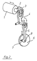
- Fig. 2 shows the friction drive of a friction roller 1 of an inking unit, not shown.
- the friction roller 1 is mounted with its pin 2 axially back and forth in the side walls of the printing machine, not shown here.
- On a pin 2 is an arm of a via a transmission ring 3 with an elongated cross section, which engages in a corresponding annular groove of the pin 2
- Angle lever 4 articulated.
- Angle lever 4 is pivotally mounted on the frame with an axis which is perpendicular to that of the friction roller.
- a rod 5 is rotatably articulated on a second arm of angle lever 4, for example by means of a fork-shaped end. The other end of the rod 5 is articulated on a crank wheel 6 of the friction drive.
- the crank wheel 6 has an elongated slot 7 in the radial direction, in which the end of the rod 5 articulated on the crank wheel 6 can be displaced when the locking screw 8 is loosened.
- the friction drive shown can also drive several friction rollers 1 via special mechanisms.
- a drive wheel 9 of the friction drive is coaxially assigned to the crank wheel 6 of the friction drive, which meshes, for example, directly with a gearwheel 10 attached to the plate cylinder (not shown here) (FIG. 1). So that not only the stroke but also the time of use for the lateral rubbing is adjustable, the drive wheel 9 can be rotated relative to the crank wheel 6, for example after loosening screws or similar locking means, so that the angular position of the crank wheel 6 can then be changed relative to the angular position of the plate cylinder .
- crank wheel 6 and the drive wheel 9 are assigned a shaft 11, which is seated via a truncated cone in a bearing arranged in the wall of the side stand 12.
- Crank wheel 6 is fixedly attached to the free end of shaft 11 (or detachable for the adjustment of the starting point of friction), drive wheel 9 is freely rotatable on shaft 11.
- the end of shaft 11 assigned to crank wheel 6 is rotatably supported via a housing part 11.2.
- Housing part 11.2 is firmly connected to the side stand 12.
- the drive wheel 9 can be locked with respect to the shaft 11 via a clutch 13 arranged on the shaft 11.
- the clutch 13 consists of a pair of toothed disks 13.1, 13.2, for example a toothed disk 13.1 on the shaft 11 is rotatably connected to the drive wheel 9 and the toothed disk 13.2 is rotatably and axially displaceably (for example via a multi-groove profile 13.3) connected to the shaft 11.
- the toothed disks 13.1, 13.2 have an L-shaped profile and on the end face such a toothing 13.4 distributed asymmetrically over the circumference, so that mutual engagement is only possible with a single angle of rotation position.
- the toothed disks 13.1, 13.2 are pressed together, for example, by a compression spring associated with the toothed disk 13.2 (disc springs - not shown -).
- the triggering device 14 can also be formed from a pressure cylinder (hydraulic / pneumatic) which can be pressurized and which is arranged in the shaft 11, for which purpose holes for the pressure medium supply would also have to be drilled in the shaft 11.
- a pressure cylinder hydraulic / pneumatic
- frictional clutches could also be used.
- the triggering device 14 of a friction clutch (for example hydraulic) is then acted upon at the exact time with the corresponding working medium, so that the separation or closing of the torque flow between the drive wheel 9 and the crank wheel 6 takes place only at a specific angular position of these wheels.
- the corresponding time switching points for this would be a rotary angle sensor attached to a single-speed shaft of the printing press, in addition to a computer with a stored target angle position can be removed.
- the triggering device 14 would then be controlled by correspondingly rapidly reacting solenoid valves.
- the release device 14 and the frictional properties of the clutch parts would then be dimensioned such that there is only negligible slip during the switching operations.
Landscapes
- Inking, Control Or Cleaning Of Printing Machines (AREA)
- Impression-Transfer Materials And Handling Thereof (AREA)
Applications Claiming Priority (2)
| Application Number | Priority Date | Filing Date | Title |
|---|---|---|---|
| DE4140048 | 1991-12-05 | ||
| DE4140048A DE4140048C2 (de) | 1991-12-05 | 1991-12-05 | Farbwerk einer Druckmaschine, insbesondere Bogenoffsetdruckmaschine |
Publications (2)
| Publication Number | Publication Date |
|---|---|
| EP0545237A1 true EP0545237A1 (fr) | 1993-06-09 |
| EP0545237B1 EP0545237B1 (fr) | 1994-09-28 |
Family
ID=6446293
Family Applications (1)
| Application Number | Title | Priority Date | Filing Date |
|---|---|---|---|
| EP92120031A Expired - Lifetime EP0545237B1 (fr) | 1991-12-05 | 1992-11-25 | Unité d'encrage pour une machine d'impression, particulièrement machine d'impression offset pour feuilles |
Country Status (5)
| Country | Link |
|---|---|
| US (1) | US5249523A (fr) |
| EP (1) | EP0545237B1 (fr) |
| JP (1) | JPH07102698B2 (fr) |
| AT (1) | ATE112213T1 (fr) |
| DE (2) | DE4140048C2 (fr) |
Cited By (4)
| Publication number | Priority date | Publication date | Assignee | Title |
|---|---|---|---|---|
| US5701817A (en) * | 1994-10-08 | 1997-12-30 | Heidelberger Druckmaschinen Aktiengesellschaft | Apparatus for adjusting the movement of a roller in a printing press |
| EP0924072A1 (fr) * | 1997-12-17 | 1999-06-23 | Heidelberger Druckmaschinen Aktiengesellschaft | Procédé d'opération d'une machine rotative d'impression et dispositif dans une machine rotative d'impression |
| EP1125739A3 (fr) * | 2000-02-18 | 2001-10-04 | Mitsubishi Heavy Industries, Ltd. | Mettre en action une machine offset-feuilles comprenant un rouleau baladeur |
| DE102004048149A1 (de) * | 2004-10-02 | 2006-04-06 | Koenig & Bauer Ag | Verfahren zum Betreiben eines Farbwerkes einer Rotationsdruckmaschine |
Families Citing this family (5)
| Publication number | Priority date | Publication date | Assignee | Title |
|---|---|---|---|---|
| DE4445964B4 (de) * | 1994-12-22 | 2005-12-01 | Heidelberger Druckmaschinen Ag | Farbwerk einer Druckmaschine |
| DE19505625C2 (de) * | 1995-02-18 | 1996-12-12 | Roland Man Druckmasch | Zwangsantrieb für eine Farbwerkwalze in einer Druckmaschine |
| DE19821652A1 (de) * | 1997-10-02 | 1999-04-08 | Heidelberger Druckmasch Ag | Farbwerk für Druckmaschinen |
| DE10003026B4 (de) * | 2000-01-25 | 2004-03-25 | Koenig & Bauer Ag | Antrieb für eine Reibwalze |
| PT2509797E (pt) * | 2009-12-07 | 2015-01-05 | Felix Böttcher GmbH & Co KG | Rolos de distribuição |
Citations (6)
| Publication number | Priority date | Publication date | Assignee | Title |
|---|---|---|---|---|
| US3013489A (en) * | 1957-10-01 | 1961-12-19 | Samuel M Langston Co | Printing machine ink roll vibrator |
| EP0000329A1 (fr) * | 1977-07-09 | 1979-01-24 | Heidelberger Druckmaschinen Aktiengesellschaft | Entraînement avec moyens d'entraînement pour agiter axialement en va-et-vient les rouleaux balladeurs d'un dispositif d'encrage |
| DE2854032A1 (de) * | 1978-12-14 | 1980-06-19 | Maschf Augsburg Nuernberg Ag | Wellenkupplung mit einer synchronisiervorrichtung |
| DE3424721A1 (de) * | 1984-07-05 | 1986-01-16 | M.A.N.- Roland Druckmaschinen AG, 6050 Offenbach | Farbwerk fuer eine druckmaschine |
| US4869167A (en) * | 1988-06-07 | 1989-09-26 | Royse Engineering, Inc. | Variable speed oscillating roller |
| EP0418778A2 (fr) * | 1989-09-20 | 1991-03-27 | KOENIG & BAUER-ALBERT Aktiengesellschaft | Rouleaux applicateurs à mouvement de va-et-vient |
Family Cites Families (14)
| Publication number | Priority date | Publication date | Assignee | Title |
|---|---|---|---|---|
| DE113718C (fr) * | ||||
| DE454953C (de) * | 1926-01-29 | 1928-01-21 | Schwarz Presse Akt Ges | Farbwerk fuer Rotationsflachdruckmaschinen |
| DE1761389A1 (de) * | 1968-05-13 | 1971-06-03 | Polygraph Leipzig | Vorrichtung zum Verstellen des Reibzylinderhubes in Farbwerken von Rotationsdruckmaschinen |
| GB1319509A (en) * | 1970-01-26 | 1973-06-06 | Adamovske Strojirny Np | Tripping of ink forme rollers on printing machines |
| US3715979A (en) * | 1970-07-09 | 1973-02-13 | Fortuna Werke Maschf Ag | Offset printing machine |
| DE2340300C3 (de) * | 1973-08-09 | 1979-09-13 | Roland Offsetmaschinenfabrik Faber & Schleicher Ag, 6050 Offenbach | Farbkastenwalze für ein Heberfarbwerk an Druckmaschinen |
| DD113718A1 (fr) * | 1974-05-20 | 1975-06-20 | ||
| DE2443504C3 (de) * | 1974-09-11 | 1978-11-23 | Roland Offsetmaschinenfabrik Faber & Schleicher Ag, 6050 Offenbach | Farbwerk an Druckmaschinen |
| DE3034644C2 (de) * | 1980-09-13 | 1982-10-07 | M.A.N.- Roland Druckmaschinen AG, 6050 Offenbach | Farbwerk mit changierenden Farbauftragswalzen |
| DE3146223C2 (de) * | 1981-11-21 | 1985-03-21 | Heidelberger Druckmaschinen Ag, 6900 Heidelberg | Feucht-Farbwerk für Offsetdruckmaschinen |
| US5065676A (en) * | 1986-08-04 | 1991-11-19 | Hardin Philip J | Axially reversing roller for printing presses and sheet coating machines |
| CH682895A5 (fr) * | 1990-04-23 | 1993-12-15 | Bobst Sa | Dispositif de déplacement des baladeurs dans une machine d'impression. |
| DE4032470A1 (de) * | 1990-10-12 | 1992-04-30 | Wifag Maschf | Vorrichtung zur stufenlosen verstellung der axialen verreibungsbewegung von reibwalzen |
| DE4113491A1 (de) * | 1991-04-25 | 1992-10-29 | Koenig & Bauer Ag | Verreibwalze fuer druckmaschinen |
-
1991
- 1991-12-05 DE DE4140048A patent/DE4140048C2/de not_active Expired - Fee Related
-
1992
- 1992-11-25 AT AT92120031T patent/ATE112213T1/de not_active IP Right Cessation
- 1992-11-25 EP EP92120031A patent/EP0545237B1/fr not_active Expired - Lifetime
- 1992-11-25 DE DE59200568T patent/DE59200568D1/de not_active Expired - Fee Related
- 1992-12-04 JP JP4325400A patent/JPH07102698B2/ja not_active Expired - Fee Related
- 1992-12-07 US US07/986,588 patent/US5249523A/en not_active Expired - Fee Related
Patent Citations (6)
| Publication number | Priority date | Publication date | Assignee | Title |
|---|---|---|---|---|
| US3013489A (en) * | 1957-10-01 | 1961-12-19 | Samuel M Langston Co | Printing machine ink roll vibrator |
| EP0000329A1 (fr) * | 1977-07-09 | 1979-01-24 | Heidelberger Druckmaschinen Aktiengesellschaft | Entraînement avec moyens d'entraînement pour agiter axialement en va-et-vient les rouleaux balladeurs d'un dispositif d'encrage |
| DE2854032A1 (de) * | 1978-12-14 | 1980-06-19 | Maschf Augsburg Nuernberg Ag | Wellenkupplung mit einer synchronisiervorrichtung |
| DE3424721A1 (de) * | 1984-07-05 | 1986-01-16 | M.A.N.- Roland Druckmaschinen AG, 6050 Offenbach | Farbwerk fuer eine druckmaschine |
| US4869167A (en) * | 1988-06-07 | 1989-09-26 | Royse Engineering, Inc. | Variable speed oscillating roller |
| EP0418778A2 (fr) * | 1989-09-20 | 1991-03-27 | KOENIG & BAUER-ALBERT Aktiengesellschaft | Rouleaux applicateurs à mouvement de va-et-vient |
Cited By (7)
| Publication number | Priority date | Publication date | Assignee | Title |
|---|---|---|---|---|
| US5701817A (en) * | 1994-10-08 | 1997-12-30 | Heidelberger Druckmaschinen Aktiengesellschaft | Apparatus for adjusting the movement of a roller in a printing press |
| EP0924072A1 (fr) * | 1997-12-17 | 1999-06-23 | Heidelberger Druckmaschinen Aktiengesellschaft | Procédé d'opération d'une machine rotative d'impression et dispositif dans une machine rotative d'impression |
| US6578481B1 (en) | 1997-12-17 | 2003-06-17 | Heidelberger Druckmaschinen Ag | Method and device for operating a rotary printing press |
| EP1125739A3 (fr) * | 2000-02-18 | 2001-10-04 | Mitsubishi Heavy Industries, Ltd. | Mettre en action une machine offset-feuilles comprenant un rouleau baladeur |
| US6612233B2 (en) | 2000-02-18 | 2003-09-02 | Mitsubishi Heavy Industries, Ltd. | Sheet feed offset press |
| DE102004048149A1 (de) * | 2004-10-02 | 2006-04-06 | Koenig & Bauer Ag | Verfahren zum Betreiben eines Farbwerkes einer Rotationsdruckmaschine |
| DE102004048149B4 (de) * | 2004-10-02 | 2015-10-15 | Koenig & Bauer Ag | Verfahren zum Betreiben eines Farbwerkes einer Rotationsdruckmaschine |
Also Published As
| Publication number | Publication date |
|---|---|
| JPH07102698B2 (ja) | 1995-11-08 |
| ATE112213T1 (de) | 1994-10-15 |
| DE4140048A1 (de) | 1993-06-09 |
| JPH05254100A (ja) | 1993-10-05 |
| DE59200568D1 (de) | 1994-11-03 |
| US5249523A (en) | 1993-10-05 |
| EP0545237B1 (fr) | 1994-09-28 |
| DE4140048C2 (de) | 1995-09-21 |
Similar Documents
| Publication | Publication Date | Title |
|---|---|---|
| DE3110468C2 (fr) | ||
| EP0242661B1 (fr) | Dispositif de positionnement d'un ensemble d'impression à cinq cylindres d'une rotative offset | |
| DE69806403T2 (de) | Druckeinheit | |
| EP0545237B1 (fr) | Unité d'encrage pour une machine d'impression, particulièrement machine d'impression offset pour feuilles | |
| EP2406077B1 (fr) | Unité d'impression d'une machine d'impression comportant au moins une imprimante | |
| EP0549884B1 (fr) | Dispositif pour la séparation d'un train d'engrenage | |
| DE2703424C2 (de) | Farbwerk für Offset-Druckmaschinen | |
| DE3917074A1 (de) | Farbwerk | |
| EP1593498B1 (fr) | Dispositif d'entraînement d'un rouleau toucheur de mouillage dans rotatives d'impression | |
| DE10129762B4 (de) | Druckeinheit | |
| DE2901236A1 (de) | Vorrichtung zum verstellen des antriebes an bogenrotationsdruckmaschinen fuer wahlweisen schoen- oder schoen- und widerdruck | |
| EP0696503A2 (fr) | Procédé et entrainement du preneur pour alimenter de l'encre dans un dispositif encrier à preneur d'une machine à imprimer | |
| DE19545114A1 (de) | Antrieb für mehrere Übertragungszylinder einer Druckmaschine | |
| DE1194873B (de) | Farbwerk fuer Rotationsdruckmaschinen | |
| DE102004048149A1 (de) | Verfahren zum Betreiben eines Farbwerkes einer Rotationsdruckmaschine | |
| DD242029A1 (de) | Vorrichtung zum wahlweisen axialen bewegen von farbauftragwalzen | |
| DE8628072U1 (de) | Umschalteinrichtung an der Wendetrommel einer Bogenrotationsdruckmaschine | |
| DE2336061B2 (de) | Antrieb fuer die verreibwalzen eines farbwerks einer druckmaschine | |
| DE10003026A1 (de) | Antrieb für eine Reibwalze | |
| DE1436529C3 (fr) | ||
| DE102007026011B4 (de) | Vorrichtung zur Umfangs- und Seitenverstellung eines Zylinders | |
| DE10347152B4 (de) | Kurvensteuervorrichtung für ein Bogenhaltesystem in einer Verarbeitungsmaschine | |
| EP0951997B1 (fr) | Système d'encrage à preneur pour une machine à imprimer | |
| DD233974A1 (de) | Farbheberantrieb fuer druckmaschinen | |
| DE2215504B2 (de) | Mehrfarbenbogenrotationsdruckmaschine |
Legal Events
| Date | Code | Title | Description |
|---|---|---|---|
| PUAI | Public reference made under article 153(3) epc to a published international application that has entered the european phase |
Free format text: ORIGINAL CODE: 0009012 |
|
| 17P | Request for examination filed |
Effective date: 19921204 |
|
| AK | Designated contracting states |
Kind code of ref document: A1 Designated state(s): AT CH DE FR GB IT LI |
|
| 17Q | First examination report despatched |
Effective date: 19930709 |
|
| ITF | It: translation for a ep patent filed | ||
| GRAA | (expected) grant |
Free format text: ORIGINAL CODE: 0009210 |
|
| AK | Designated contracting states |
Kind code of ref document: B1 Designated state(s): AT CH DE FR GB IT LI |
|
| REF | Corresponds to: |
Ref document number: 112213 Country of ref document: AT Date of ref document: 19941015 Kind code of ref document: T |
|
| ET | Fr: translation filed | ||
| REF | Corresponds to: |
Ref document number: 59200568 Country of ref document: DE Date of ref document: 19941103 |
|
| GBT | Gb: translation of ep patent filed (gb section 77(6)(a)/1977) |
Effective date: 19941012 |
|
| PLBE | No opposition filed within time limit |
Free format text: ORIGINAL CODE: 0009261 |
|
| STAA | Information on the status of an ep patent application or granted ep patent |
Free format text: STATUS: NO OPPOSITION FILED WITHIN TIME LIMIT |
|
| 26N | No opposition filed | ||
| PGFP | Annual fee paid to national office [announced via postgrant information from national office to epo] |
Ref country code: AT Payment date: 19981020 Year of fee payment: 7 |
|
| PGFP | Annual fee paid to national office [announced via postgrant information from national office to epo] |
Ref country code: CH Payment date: 19981023 Year of fee payment: 7 |
|
| PG25 | Lapsed in a contracting state [announced via postgrant information from national office to epo] |
Ref country code: AT Free format text: LAPSE BECAUSE OF NON-PAYMENT OF DUE FEES Effective date: 19991125 |
|
| PG25 | Lapsed in a contracting state [announced via postgrant information from national office to epo] |
Ref country code: LI Free format text: LAPSE BECAUSE OF NON-PAYMENT OF DUE FEES Effective date: 19991130 Ref country code: CH Free format text: LAPSE BECAUSE OF NON-PAYMENT OF DUE FEES Effective date: 19991130 |
|
| REG | Reference to a national code |
Ref country code: CH Ref legal event code: PL |
|
| PGFP | Annual fee paid to national office [announced via postgrant information from national office to epo] |
Ref country code: GB Payment date: 20001013 Year of fee payment: 9 |
|
| PGFP | Annual fee paid to national office [announced via postgrant information from national office to epo] |
Ref country code: FR Payment date: 20001101 Year of fee payment: 9 |
|
| PG25 | Lapsed in a contracting state [announced via postgrant information from national office to epo] |
Ref country code: GB Free format text: LAPSE BECAUSE OF NON-PAYMENT OF DUE FEES Effective date: 20011125 |
|
| REG | Reference to a national code |
Ref country code: GB Ref legal event code: IF02 |
|
| GBPC | Gb: european patent ceased through non-payment of renewal fee |
Effective date: 20011125 |
|
| PG25 | Lapsed in a contracting state [announced via postgrant information from national office to epo] |
Ref country code: FR Free format text: LAPSE BECAUSE OF NON-PAYMENT OF DUE FEES Effective date: 20020730 |
|
| REG | Reference to a national code |
Ref country code: FR Ref legal event code: ST |
|
| REG | Reference to a national code |
Ref country code: FR Ref legal event code: ST |
|
| PG25 | Lapsed in a contracting state [announced via postgrant information from national office to epo] |
Ref country code: IT Free format text: LAPSE BECAUSE OF NON-PAYMENT OF DUE FEES;WARNING: LAPSES OF ITALIAN PATENTS WITH EFFECTIVE DATE BEFORE 2007 MAY HAVE OCCURRED AT ANY TIME BEFORE 2007. THE CORRECT EFFECTIVE DATE MAY BE DIFFERENT FROM THE ONE RECORDED. Effective date: 20051125 |
|
| PGFP | Annual fee paid to national office [announced via postgrant information from national office to epo] |
Ref country code: DE Payment date: 20081121 Year of fee payment: 17 |
|
| PG25 | Lapsed in a contracting state [announced via postgrant information from national office to epo] |
Ref country code: DE Free format text: LAPSE BECAUSE OF NON-PAYMENT OF DUE FEES Effective date: 20100601 |