EP0565065A1 - Beschleunigungsmessaufnehmer - Google Patents
Beschleunigungsmessaufnehmer Download PDFInfo
- Publication number
- EP0565065A1 EP0565065A1 EP93105712A EP93105712A EP0565065A1 EP 0565065 A1 EP0565065 A1 EP 0565065A1 EP 93105712 A EP93105712 A EP 93105712A EP 93105712 A EP93105712 A EP 93105712A EP 0565065 A1 EP0565065 A1 EP 0565065A1
- Authority
- EP
- European Patent Office
- Prior art keywords
- vibrator
- piezoelectric elements
- acceleration sensor
- piezoelectric
- acceleration
- Prior art date
- Legal status (The legal status is an assumption and is not a legal conclusion. Google has not performed a legal analysis and makes no representation as to the accuracy of the status listed.)
- Granted
Links
Images


Classifications
-
- G—PHYSICS
- G01—MEASURING; TESTING
- G01P—MEASURING LINEAR OR ANGULAR SPEED, ACCELERATION, DECELERATION, OR SHOCK; INDICATING PRESENCE, ABSENCE, OR DIRECTION, OF MOVEMENT
- G01P15/00—Measuring acceleration; Measuring deceleration; Measuring shock, i.e. sudden change of acceleration
- G01P15/18—Measuring acceleration; Measuring deceleration; Measuring shock, i.e. sudden change of acceleration in two or more dimensions
-
- G—PHYSICS
- G01—MEASURING; TESTING
- G01P—MEASURING LINEAR OR ANGULAR SPEED, ACCELERATION, DECELERATION, OR SHOCK; INDICATING PRESENCE, ABSENCE, OR DIRECTION, OF MOVEMENT
- G01P15/00—Measuring acceleration; Measuring deceleration; Measuring shock, i.e. sudden change of acceleration
- G01P15/02—Measuring acceleration; Measuring deceleration; Measuring shock, i.e. sudden change of acceleration by making use of inertia forces using solid seismic masses
- G01P15/08—Measuring acceleration; Measuring deceleration; Measuring shock, i.e. sudden change of acceleration by making use of inertia forces using solid seismic masses with conversion into electric or magnetic values
- G01P15/09—Measuring acceleration; Measuring deceleration; Measuring shock, i.e. sudden change of acceleration by making use of inertia forces using solid seismic masses with conversion into electric or magnetic values by piezoelectric pick-up
- G01P15/0922—Measuring acceleration; Measuring deceleration; Measuring shock, i.e. sudden change of acceleration by making use of inertia forces using solid seismic masses with conversion into electric or magnetic values by piezoelectric pick-up of the bending or flexing mode type
Definitions
- This invention relates to an acceleration sensor and, more particularly, to the accelaration sensor using a piezoelectric body.
- a cantilever type supported by one end of the piezoelectric body or a twin-support type supported by both ends of a vibrator was available.
- the acceleration sensor of such a conventional type was unable to detect slight acceleration as weak as 0.001G.
- the principal object of the present invention is to provide an acceleration sensor which can measure slight acceleration with accuracy.
- the present invention is an acceleration sensor comprising a vibrator of a polygonal prism shape which is rotation symmetric with respect to its axis, and piezoelectric elements formed on a plurality of side faces of the vibrator which are rotation symmetric with respect to the axis of the vibrator, wherein the direction of polarization of the piezoelectric elements are same direction with respect to the axis of the vibrator.
- a resonance frequency of the longitudinal vibration is equalized to a resonance frequency of the bending vibration.
- the vibrator vibrates in the longitudinal direction by applying a driving signal of the same phase to the plurality of the piezoelectric elements to give inertia to the vibrator.
- a driving signal of the same phase to the plurality of the piezoelectric elements to give inertia to the vibrator.
- the vibrator is deflected.
- the deflection of the vibrator becomes large by equalizing the resonance frequency of the longitudinal vibration of the vibrator and the resonance frequency of the bending vibration of the vibrator.
- the vibrator when the vibrator is deflected by applying acceleration to it, voltages generate in the piezoelectric elements depending upon a magnitude of the deflection.
- the direction in which the acceleration is applied and the acceleration value can be measured.
- the deflection of the vibrator becomes large by equalizing the resonance frequency of the longitudinal vibration of the vibrator and the resonance frequency of the bending vibration of the vibrator, and this enables to detect a slight acceleration.
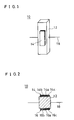
- Fig. 1 is a perspective view showing one embodiment of the present invention.
- Fig. 2 is a sectional view showing the acceleration sensor of Fig. 1.
- Fig. 3 is an illustrative view showing a state in which acceleration is not applied to the acceleration sensor of Fig. 1.
- Fig. 4 is an illustrative view showing a state in which acceleration is applied to the acceleration sensor of Fig. 1.
- Fig. 5 is an illustrative view showing an another embodient of the present invention.
- Fig. 1 is a perspective view showing one embodiment of the present invention
- Fig. 2 is its sectional view.
- the acceleration sensor 10 includes, for example, a regular quadrangular prism shaped vibrator 12.
- the vibrator 12 is formed of, for example, a constant elastic metal material such as elinvar.
- piezoelectric elements 14 and 16 are formed on their center portions respectively.
- the piezoelectric element 14 includes a piezoelectric body 14a made of piezoelectric ceramics or the like. On both surfaces of the piezoelectric body 14a, electrodes 14b and 14c are formed. And one electrode 14c is bonded to a side face of the vibrator 12.
- the piezoelectric element 16 includes a piezoelectric body 16a, on both surfaces of which electrodes 16b and 16c are formed respectively.
- One electrode 16c is bonded to a side face of the vibrator 12.
- the piezoelectric bodies 14a and 16a of these piezoelectric elements 14 and 16 are polarized from the outside toward the side of the vibrator 12 respectively. That is, the piezoelectric body 14a is polarized from the side of the electrode 14b toward the side of the electrode 14c, and the piezoelectric body 16a is polarized from the side of the electrode 16b toward the side of the electrode 16c.
- supporting members 18 for supporting the vibrator 12 are fixed.
- an oscillation circuit 20 is connected in parallel to the piezoelectric elements 14 and 16 of the acceleration sensor 10.
- a signal from the oscillation circuit 20 is applied to the piezoelectric elements 14 and 16 via a resistor 22 and 24 respectively.
- the signals applied to the piezoelectric elements 14 and 16 respectively are of the same phase. Because the respective piezoelectric elements 14 and 16 have been polarized from the outside toward the side of the vibrator 12, the vibrator 12 vibrates in its longitudinal direction as shown with the arrows of Fig. 3. Inertia is given to the vibrator 12 by vibration of itself in its longitudinal direction.
- the piezoelectric elements 14 and 16 are respectively connected to input terminals of an operational amplifier 26 for differential amplificaion. Therefore, an output corresponding to a voltage difference between the voltages generated in the piezoelectric elements 14 and 16 is obtained at the output terminal of the operational amplifier 26.
- an output corresponding to a voltage difference between the voltages generated in the piezoelectric elements 14 and 16 is obtained at the output terminal of the operational amplifier 26.
- the piezoelectric bodies 14a and 16a have been polarized from the outside toward the side of the vibrator 12, voltages generated in the piezoelectric elements 14 and 16 when acceleration is applied have an opposite phase respectively. Therefore, when measuring a voltage difference between the output voltages of the piezoelectric elements 14 and 16, a large value of the output can be obtained. Thus, a slight acceleration can be correctly measured. Furthermore, when a resonance frequency of the longitudinal vibration of the vibrator 12 is equalized to a resonance frequency of the bending vibration of the vibrator 12, the deflection of the vibrator 12 becomes large at application of acceleration. Therefore, the sensor can sense a slight acceleration, thereby providing a good sensitivity.
- Fig. 5 is a circuit diagram showing another embodiment of the present invention.
- the vibrator 12 is formed in a regular triangular prism shape.
- piezoelectric elements 30, 32 and 34 are formed on the center portion of each side face of the vibrator 12.
- the piezoelectric bodies of these piezoelectric elements 30, 32 and 34 also are polarized from the outside toward the side of the vibrator 12.
- An oscillation circuit 20 is connected in parallel to these piezoelectric elements 30, 32 and 34 via resistors 36, 38 and 40 respectively.
- Two of the piezoelectric elements 30, 32 and 34 are combined and connected to input terminals of operational amplifiers 42, 44 and 46. That is, the piezoelectric elements 30 and 32 are connected to the two input terminals of the operational amplifier 46, and the piezoelectric elements 32 and 34 are connected to the two input terminals of the operational amplifier 44, and the piezoelectric elements 30 and 34 are connected to the two input terminals of the operational amplifier 42.
- the vibrator 12 vibrates in its longitudinal direction by the signal of the oscillation circuit 20.
- the vibrator 12 is deflected.
- voltages generate in the respective piezoelectric elements 30, 32 and 34. That is, in the piezoelectric elements 30, 32 and 34, the voltage corresponding to an acceleration component in the direction perpendicular to each side face of the vibrator 12 is generated.
- an output corresponding to a voltage difference between the output voltages of the piezoelectric elements connected to the respective input terminals of the operational amplifier is obtained from the respective operational amplifiers 42, 44 and 46. Therefore, when measuring the values of the outputs from these operational amplifiers 42, 44 and 46, the value and the direction of acceleration can be detected.
- the vibrator 12 may have other shapes including, for example, a regular pentagonal prism shape.
- the piezoelectric element is formed on the center portion of each side face of the regular pentagonal prism shaped vibrator.
- the piezoelectric body of each piezoelectric element is polarized from the outside toward the vibrator side.
- any shape of the vibrator 12 may be used if it is a prism shape which is rotation symmetric with respect to its axis.
- the piezoelectric elements are not necessarily formed on all side faces of the vibrator, but it is necessary to arrange the piezoelectric elements in rotation symmetry to the prism axis.
- the shape of the vibrator 12 is not limited to a regular polygonal prism shape, and any polygonal prism shape may be used if it is rotational symmetric with respect to its axis.
- the piezoelectric bodies are polarized from the outside toward the vibrator side, however, all piezoelectric bodies may be polarized from the vibrator side toward the outside. That is, any direction of polarization of the piezoelectric bodies is accetable if they are the same direction with respect to the axis of the vibrator.
Landscapes
- Physics & Mathematics (AREA)
- General Physics & Mathematics (AREA)
- Gyroscopes (AREA)
Applications Claiming Priority (2)
| Application Number | Priority Date | Filing Date | Title |
|---|---|---|---|
| JP11835392A JP3151927B2 (ja) | 1992-04-10 | 1992-04-10 | 加速度センサ |
| JP118353/92 | 1992-04-10 |
Publications (2)
| Publication Number | Publication Date |
|---|---|
| EP0565065A1 true EP0565065A1 (de) | 1993-10-13 |
| EP0565065B1 EP0565065B1 (de) | 1996-06-05 |
Family
ID=14734601
Family Applications (1)
| Application Number | Title | Priority Date | Filing Date |
|---|---|---|---|
| EP93105712A Expired - Lifetime EP0565065B1 (de) | 1992-04-10 | 1993-04-06 | Beschleunigungsmessaufnehmer |
Country Status (4)
| Country | Link |
|---|---|
| US (1) | US5415039A (de) |
| EP (1) | EP0565065B1 (de) |
| JP (1) | JP3151927B2 (de) |
| DE (1) | DE69302953T2 (de) |
Cited By (6)
| Publication number | Priority date | Publication date | Assignee | Title |
|---|---|---|---|---|
| DE19601449A1 (de) * | 1996-01-17 | 1997-07-24 | Telefunken Microelectron | Beschleunigungsfühler, insbesondere für Sicherheitssysteme in Fahrzeugen zur Personenbeförderung |
| EP0833163A1 (de) * | 1992-06-12 | 1998-04-01 | Sarcos Group | Beschleunigungsmesser |
| US9592363B2 (en) | 2003-03-27 | 2017-03-14 | Boston Scientific Scimed, Inc. | Medical device |
| US9808595B2 (en) | 2007-08-07 | 2017-11-07 | Boston Scientific Scimed, Inc | Microfabricated catheter with improved bonding structure |
| US9901706B2 (en) | 2014-04-11 | 2018-02-27 | Boston Scientific Scimed, Inc. | Catheters and catheter shafts |
| US11351048B2 (en) | 2015-11-16 | 2022-06-07 | Boston Scientific Scimed, Inc. | Stent delivery systems with a reinforced deployment sheath |
Families Citing this family (25)
| Publication number | Priority date | Publication date | Assignee | Title |
|---|---|---|---|---|
| JPH08159779A (ja) | 1994-12-02 | 1996-06-21 | Murata Mfg Co Ltd | 振動ジャイロ |
| JP3291968B2 (ja) * | 1994-12-15 | 2002-06-17 | 株式会社村田製作所 | 振動ジャイロ |
| JPH08247770A (ja) * | 1995-03-14 | 1996-09-27 | Murata Mfg Co Ltd | 振動ジャイロ |
| JP2996137B2 (ja) * | 1995-03-31 | 1999-12-27 | 株式会社村田製作所 | 振動ジャイロ |
| JPH08278146A (ja) * | 1995-04-03 | 1996-10-22 | Murata Mfg Co Ltd | 振動ジャイロ |
| US20030069522A1 (en) | 1995-12-07 | 2003-04-10 | Jacobsen Stephen J. | Slotted medical device |
| ES2274984T3 (es) | 2001-07-05 | 2007-06-01 | Precision Vascular Systems, Inc. | Dispositivo medico de punta blanda que puede someterse a torsion y metodo para conformarlo. |
| US7914467B2 (en) | 2002-07-25 | 2011-03-29 | Boston Scientific Scimed, Inc. | Tubular member having tapered transition for use in a medical device |
| JP4602080B2 (ja) | 2002-07-25 | 2010-12-22 | ボストン サイエンティフィック リミテッド | 人体構造内を進行する医療用具 |
| US8377035B2 (en) | 2003-01-17 | 2013-02-19 | Boston Scientific Scimed, Inc. | Unbalanced reinforcement members for medical device |
| US7169118B2 (en) | 2003-02-26 | 2007-01-30 | Scimed Life Systems, Inc. | Elongate medical device with distal cap |
| US7824345B2 (en) | 2003-12-22 | 2010-11-02 | Boston Scientific Scimed, Inc. | Medical device with push force limiter |
| US7365827B2 (en) * | 2004-12-08 | 2008-04-29 | Asml Netherlands B.V. | Lithographic apparatus and device manufacturing method |
| US7850623B2 (en) | 2005-10-27 | 2010-12-14 | Boston Scientific Scimed, Inc. | Elongate medical device with continuous reinforcement member |
| US8551020B2 (en) | 2006-09-13 | 2013-10-08 | Boston Scientific Scimed, Inc. | Crossing guidewire |
| US8556914B2 (en) | 2006-12-15 | 2013-10-15 | Boston Scientific Scimed, Inc. | Medical device including structure for crossing an occlusion in a vessel |
| JP2008233029A (ja) * | 2007-03-23 | 2008-10-02 | Seiko Epson Corp | 加速度センサおよび電子機器 |
| JP2008241547A (ja) * | 2007-03-28 | 2008-10-09 | Seiko Epson Corp | 加速度センサおよび電子機器 |
| US8409114B2 (en) | 2007-08-02 | 2013-04-02 | Boston Scientific Scimed, Inc. | Composite elongate medical device including distal tubular member |
| US8105246B2 (en) | 2007-08-03 | 2012-01-31 | Boston Scientific Scimed, Inc. | Elongate medical device having enhanced torque and methods thereof |
| US8821477B2 (en) | 2007-08-06 | 2014-09-02 | Boston Scientific Scimed, Inc. | Alternative micromachined structures |
| US7841994B2 (en) | 2007-11-02 | 2010-11-30 | Boston Scientific Scimed, Inc. | Medical device for crossing an occlusion in a vessel |
| US8376961B2 (en) | 2008-04-07 | 2013-02-19 | Boston Scientific Scimed, Inc. | Micromachined composite guidewire structure with anisotropic bending properties |
| US8535243B2 (en) | 2008-09-10 | 2013-09-17 | Boston Scientific Scimed, Inc. | Medical devices and tapered tubular members for use in medical devices |
| CN102507982B (zh) * | 2011-11-02 | 2013-09-04 | 重庆理工大学 | 一种基于光热效应的硅微谐振式二维加速度传感器 |
Citations (4)
| Publication number | Priority date | Publication date | Assignee | Title |
|---|---|---|---|---|
| US2722614A (en) * | 1951-08-11 | 1955-11-01 | Gulton Mfg Co | Vibration and shock-responsive device |
| DE2845008A1 (de) * | 1978-10-16 | 1980-04-30 | Philips Patentverwaltung | Beschleunigungsaufnehmer |
| DE3817354A1 (de) * | 1987-05-21 | 1988-12-01 | Nissan Motor | Sensor zur erfassung kinetischer energie, insbesondere piezoelektrischer sensor zur erfassung dynamischer oder kinetischer energie |
| DE3926504A1 (de) * | 1988-08-12 | 1990-02-15 | Murata Manufacturing Co | Schwingungserreger und diesen verwendender schwingkreisel |
Family Cites Families (2)
| Publication number | Priority date | Publication date | Assignee | Title |
|---|---|---|---|---|
| GB8325861D0 (en) * | 1983-09-28 | 1983-11-02 | Syrinx Presicion Instr Ltd | Force transducer |
| DE69111950T2 (de) * | 1990-08-27 | 1996-03-14 | Murata Manufacturing Co | Signaldetektorschaltung für Schwingkreisel. |
-
1992
- 1992-04-10 JP JP11835392A patent/JP3151927B2/ja not_active Expired - Fee Related
-
1993
- 1993-03-29 US US08/038,490 patent/US5415039A/en not_active Expired - Lifetime
- 1993-04-06 DE DE69302953T patent/DE69302953T2/de not_active Expired - Fee Related
- 1993-04-06 EP EP93105712A patent/EP0565065B1/de not_active Expired - Lifetime
Patent Citations (4)
| Publication number | Priority date | Publication date | Assignee | Title |
|---|---|---|---|---|
| US2722614A (en) * | 1951-08-11 | 1955-11-01 | Gulton Mfg Co | Vibration and shock-responsive device |
| DE2845008A1 (de) * | 1978-10-16 | 1980-04-30 | Philips Patentverwaltung | Beschleunigungsaufnehmer |
| DE3817354A1 (de) * | 1987-05-21 | 1988-12-01 | Nissan Motor | Sensor zur erfassung kinetischer energie, insbesondere piezoelektrischer sensor zur erfassung dynamischer oder kinetischer energie |
| DE3926504A1 (de) * | 1988-08-12 | 1990-02-15 | Murata Manufacturing Co | Schwingungserreger und diesen verwendender schwingkreisel |
Cited By (7)
| Publication number | Priority date | Publication date | Assignee | Title |
|---|---|---|---|---|
| EP0833163A1 (de) * | 1992-06-12 | 1998-04-01 | Sarcos Group | Beschleunigungsmesser |
| DE19601449A1 (de) * | 1996-01-17 | 1997-07-24 | Telefunken Microelectron | Beschleunigungsfühler, insbesondere für Sicherheitssysteme in Fahrzeugen zur Personenbeförderung |
| US9592363B2 (en) | 2003-03-27 | 2017-03-14 | Boston Scientific Scimed, Inc. | Medical device |
| US10207077B2 (en) | 2003-03-27 | 2019-02-19 | Boston Scientific Scimed, Inc. | Medical device |
| US9808595B2 (en) | 2007-08-07 | 2017-11-07 | Boston Scientific Scimed, Inc | Microfabricated catheter with improved bonding structure |
| US9901706B2 (en) | 2014-04-11 | 2018-02-27 | Boston Scientific Scimed, Inc. | Catheters and catheter shafts |
| US11351048B2 (en) | 2015-11-16 | 2022-06-07 | Boston Scientific Scimed, Inc. | Stent delivery systems with a reinforced deployment sheath |
Also Published As
| Publication number | Publication date |
|---|---|
| DE69302953D1 (de) | 1996-07-11 |
| JPH05288774A (ja) | 1993-11-02 |
| DE69302953T2 (de) | 1996-12-19 |
| EP0565065B1 (de) | 1996-06-05 |
| JP3151927B2 (ja) | 2001-04-03 |
| US5415039A (en) | 1995-05-16 |
Similar Documents
| Publication | Publication Date | Title |
|---|---|---|
| US5415039A (en) | Acceleration sensor having piezoelectric elements having the same direction of polarization | |
| US4654663A (en) | Angular rate sensor system | |
| US5770799A (en) | Piezoelectric vibrator and acceleration sensor using the same | |
| EP0685704B1 (de) | Vibrationskreisel | |
| GB2158579A (en) | Angular rate sensor system | |
| EP0520468B1 (de) | Vibrationskreisel | |
| JPH08159806A (ja) | 方位センサおよび方位距離センサ | |
| US5696322A (en) | Vibrating gyroscope | |
| US5455476A (en) | Vibrating gyroscope | |
| US5751093A (en) | Vibrating gyroscope | |
| JP3291968B2 (ja) | 振動ジャイロ | |
| US5850119A (en) | Vibration gyroscope | |
| JP3265840B2 (ja) | 圧電振動子の駆動検出回路 | |
| EP0777105B1 (de) | Vibrationskreisel und Verfahren zur Einstellung seiner Eigenschaften | |
| EP0674152A1 (de) | Drehgeschwindigkeitsdetektorschaltung für Vibrationskreisel | |
| JPH05133755A (ja) | 診断機能付振動ジヤイロ | |
| JP3129022B2 (ja) | 加速度センサ | |
| JPH07174570A (ja) | 振動ジャイロ | |
| JPH0540040A (ja) | ジヤイロ装置 | |
| JPH09159456A (ja) | 圧電振動ジャイロ用駆動検出回路 | |
| JPH0783670A (ja) | 圧電振動子の駆動・検出回路 | |
| JPS6120810A (ja) | 振動型角速度検出装置 | |
| JPH05113336A (ja) | 振動ジヤイロ | |
| JPH0854239A (ja) | 振動ジャイロ | |
| KR19980035714A (ko) | 자이로센서와 자이로센서를 이용한 각속도측정장치 |
Legal Events
| Date | Code | Title | Description |
|---|---|---|---|
| PUAI | Public reference made under article 153(3) epc to a published international application that has entered the european phase |
Free format text: ORIGINAL CODE: 0009012 |
|
| AK | Designated contracting states |
Kind code of ref document: A1 Designated state(s): DE FR GB IT SE |
|
| 17P | Request for examination filed |
Effective date: 19931105 |
|
| 17Q | First examination report despatched |
Effective date: 19950731 |
|
| GRAH | Despatch of communication of intention to grant a patent |
Free format text: ORIGINAL CODE: EPIDOS IGRA |
|
| GRAH | Despatch of communication of intention to grant a patent |
Free format text: ORIGINAL CODE: EPIDOS IGRA |
|
| GRAA | (expected) grant |
Free format text: ORIGINAL CODE: 0009210 |
|
| ITF | It: translation for a ep patent filed | ||
| AK | Designated contracting states |
Kind code of ref document: B1 Designated state(s): DE FR GB IT SE |
|
| ET | Fr: translation filed | ||
| REF | Corresponds to: |
Ref document number: 69302953 Country of ref document: DE Date of ref document: 19960711 |
|
| PLBE | No opposition filed within time limit |
Free format text: ORIGINAL CODE: 0009261 |
|
| 26N | No opposition filed | ||
| REG | Reference to a national code |
Ref country code: GB Ref legal event code: IF02 |
|
| PGFP | Annual fee paid to national office [announced via postgrant information from national office to epo] |
Ref country code: SE Payment date: 20090407 Year of fee payment: 17 Ref country code: IT Payment date: 20090424 Year of fee payment: 17 Ref country code: FR Payment date: 20090417 Year of fee payment: 17 Ref country code: DE Payment date: 20090402 Year of fee payment: 17 |
|
| PGFP | Annual fee paid to national office [announced via postgrant information from national office to epo] |
Ref country code: GB Payment date: 20090401 Year of fee payment: 17 |
|
| EUG | Se: european patent has lapsed | ||
| GBPC | Gb: european patent ceased through non-payment of renewal fee |
Effective date: 20100406 |
|
| REG | Reference to a national code |
Ref country code: FR Ref legal event code: ST Effective date: 20101230 |
|
| PG25 | Lapsed in a contracting state [announced via postgrant information from national office to epo] |
Ref country code: DE Free format text: LAPSE BECAUSE OF NON-PAYMENT OF DUE FEES Effective date: 20101103 |
|
| PG25 | Lapsed in a contracting state [announced via postgrant information from national office to epo] |
Ref country code: IT Free format text: LAPSE BECAUSE OF NON-PAYMENT OF DUE FEES Effective date: 20100406 Ref country code: GB Free format text: LAPSE BECAUSE OF NON-PAYMENT OF DUE FEES Effective date: 20100406 |
|
| PG25 | Lapsed in a contracting state [announced via postgrant information from national office to epo] |
Ref country code: FR Free format text: LAPSE BECAUSE OF NON-PAYMENT OF DUE FEES Effective date: 20100430 |
|
| PG25 | Lapsed in a contracting state [announced via postgrant information from national office to epo] |
Ref country code: SE Free format text: LAPSE BECAUSE OF NON-PAYMENT OF DUE FEES Effective date: 20100407 |