EP0572211A1 - Méthode de nettoyage ultra-sonique d'une pièce - Google Patents
Méthode de nettoyage ultra-sonique d'une pièce Download PDFInfo
- Publication number
- EP0572211A1 EP0572211A1 EP93304034A EP93304034A EP0572211A1 EP 0572211 A1 EP0572211 A1 EP 0572211A1 EP 93304034 A EP93304034 A EP 93304034A EP 93304034 A EP93304034 A EP 93304034A EP 0572211 A1 EP0572211 A1 EP 0572211A1
- Authority
- EP
- European Patent Office
- Prior art keywords
- cleaning solution
- cleaning
- ultrasonic
- dissolved oxygen
- ppm
- Prior art date
- Legal status (The legal status is an assumption and is not a legal conclusion. Google has not performed a legal analysis and makes no representation as to the accuracy of the status listed.)
- Granted
Links
- 238000004140 cleaning Methods 0.000 title claims abstract description 229
- 238000000034 method Methods 0.000 title claims description 37
- 238000004506 ultrasonic cleaning Methods 0.000 claims abstract description 80
- QVGXLLKOCUKJST-UHFFFAOYSA-N atomic oxygen Chemical compound [O] QVGXLLKOCUKJST-UHFFFAOYSA-N 0.000 claims abstract description 76
- 239000001301 oxygen Substances 0.000 claims abstract description 76
- 229910052760 oxygen Inorganic materials 0.000 claims abstract description 76
- 239000007787 solid Substances 0.000 claims description 30
- 239000007789 gas Substances 0.000 claims description 27
- 239000004094 surface-active agent Substances 0.000 claims description 11
- 238000010438 heat treatment Methods 0.000 claims description 3
- 239000000243 solution Substances 0.000 description 183
- 239000003921 oil Substances 0.000 description 44
- XAGFODPZIPBFFR-UHFFFAOYSA-N aluminium Chemical compound [Al] XAGFODPZIPBFFR-UHFFFAOYSA-N 0.000 description 16
- 229910052782 aluminium Inorganic materials 0.000 description 16
- 239000002245 particle Substances 0.000 description 10
- 239000000428 dust Substances 0.000 description 9
- 230000000694 effects Effects 0.000 description 9
- 238000002474 experimental method Methods 0.000 description 8
- 239000010721 machine oil Substances 0.000 description 8
- 239000000463 material Substances 0.000 description 8
- 239000003960 organic solvent Substances 0.000 description 7
- 239000003599 detergent Substances 0.000 description 6
- VZGDMQKNWNREIO-UHFFFAOYSA-N tetrachloromethane Chemical compound ClC(Cl)(Cl)Cl VZGDMQKNWNREIO-UHFFFAOYSA-N 0.000 description 6
- XLYOFNOQVPJJNP-UHFFFAOYSA-N water Substances O XLYOFNOQVPJJNP-UHFFFAOYSA-N 0.000 description 4
- 239000006061 abrasive grain Substances 0.000 description 3
- KYKAJFCTULSVSH-UHFFFAOYSA-N chloro(fluoro)methane Chemical compound F[C]Cl KYKAJFCTULSVSH-UHFFFAOYSA-N 0.000 description 3
- 239000008399 tap water Substances 0.000 description 3
- 235000020679 tap water Nutrition 0.000 description 3
- 238000011144 upstream manufacturing Methods 0.000 description 3
- IJGRMHOSHXDMSA-UHFFFAOYSA-N Atomic nitrogen Chemical compound N#N IJGRMHOSHXDMSA-UHFFFAOYSA-N 0.000 description 2
- 238000010521 absorption reaction Methods 0.000 description 2
- 238000001467 acupuncture Methods 0.000 description 2
- 230000007423 decrease Effects 0.000 description 2
- 238000010586 diagram Methods 0.000 description 2
- 238000009499 grossing Methods 0.000 description 2
- 239000012528 membrane Substances 0.000 description 2
- 230000004048 modification Effects 0.000 description 2
- 238000012986 modification Methods 0.000 description 2
- 239000002991 molded plastic Substances 0.000 description 2
- 238000002791 soaking Methods 0.000 description 2
- 229910001220 stainless steel Inorganic materials 0.000 description 2
- 239000010935 stainless steel Substances 0.000 description 2
- 230000009897 systematic effect Effects 0.000 description 2
- 239000004925 Acrylic resin Substances 0.000 description 1
- 229920000178 Acrylic resin Polymers 0.000 description 1
- ZAMOUSCENKQFHK-UHFFFAOYSA-N Chlorine atom Chemical compound [Cl] ZAMOUSCENKQFHK-UHFFFAOYSA-N 0.000 description 1
- CBENFWSGALASAD-UHFFFAOYSA-N Ozone Chemical compound [O-][O+]=O CBENFWSGALASAD-UHFFFAOYSA-N 0.000 description 1
- CYTYCFOTNPOANT-UHFFFAOYSA-N Perchloroethylene Chemical group ClC(Cl)=C(Cl)Cl CYTYCFOTNPOANT-UHFFFAOYSA-N 0.000 description 1
- XSTXAVWGXDQKEL-UHFFFAOYSA-N Trichloroethylene Chemical group ClC=C(Cl)Cl XSTXAVWGXDQKEL-UHFFFAOYSA-N 0.000 description 1
- 230000003444 anaesthetic effect Effects 0.000 description 1
- 125000000129 anionic group Chemical group 0.000 description 1
- 239000007864 aqueous solution Substances 0.000 description 1
- 125000002091 cationic group Chemical group 0.000 description 1
- 239000000919 ceramic Substances 0.000 description 1
- 239000003795 chemical substances by application Substances 0.000 description 1
- 239000000460 chlorine Substances 0.000 description 1
- 229910052801 chlorine Inorganic materials 0.000 description 1
- 239000010730 cutting oil Substances 0.000 description 1
- 230000003628 erosive effect Effects 0.000 description 1
- 239000011521 glass Substances 0.000 description 1
- 231100001261 hazardous Toxicity 0.000 description 1
- 229910052500 inorganic mineral Inorganic materials 0.000 description 1
- 150000002500 ions Chemical class 0.000 description 1
- 239000011707 mineral Substances 0.000 description 1
- 239000000203 mixture Substances 0.000 description 1
- 229910052757 nitrogen Inorganic materials 0.000 description 1
- 230000001105 regulatory effect Effects 0.000 description 1
- 229920006395 saturated elastomer Polymers 0.000 description 1
- 230000007928 solubilization Effects 0.000 description 1
- 238000005063 solubilization Methods 0.000 description 1
Images


Classifications
-
- B—PERFORMING OPERATIONS; TRANSPORTING
- B08—CLEANING
- B08B—CLEANING IN GENERAL; PREVENTION OF FOULING IN GENERAL
- B08B3/00—Cleaning by methods involving the use or presence of liquid or steam
- B08B3/04—Cleaning involving contact with liquid
- B08B3/10—Cleaning involving contact with liquid with additional treatment of the liquid or of the object being cleaned, e.g. by heat, by electricity or by vibration
- B08B3/12—Cleaning involving contact with liquid with additional treatment of the liquid or of the object being cleaned, e.g. by heat, by electricity or by vibration by sonic or ultrasonic vibrations
-
- B—PERFORMING OPERATIONS; TRANSPORTING
- B08—CLEANING
- B08B—CLEANING IN GENERAL; PREVENTION OF FOULING IN GENERAL
- B08B7/00—Cleaning by methods not provided for in a single other subclass or a single group in this subclass
- B08B7/02—Cleaning by methods not provided for in a single other subclass or a single group in this subclass by distortion, beating, or vibration of the surface to be cleaned
- B08B7/026—Using sound waves
- B08B7/028—Using ultrasounds
-
- B—PERFORMING OPERATIONS; TRANSPORTING
- B08—CLEANING
- B08B—CLEANING IN GENERAL; PREVENTION OF FOULING IN GENERAL
- B08B2203/00—Details of cleaning machines or methods involving the use or presence of liquid or steam
- B08B2203/007—Heating the liquid
Definitions
- the present invention relates to a method and apparatus for ultrasonically cleaning a workpiece.
- Workpieces such as ground, bored, or abraded metallic workpieces, grounded glass or ceramic workpieces, or injection- or extrusion-molded plastic workpieces are often burred immediately after they are formed. Surfaces of such workpieces may be smeared by solid foreign matter such as chips, small broken pieces resulting from burrs, and dust particles. To finish these workpieces, it is necessary to remove the burrs and solid foreign matter off their surfaces and clean the surfaces.
- a cleaning solution such as an organic solvent of carbon chloride, e.g., perchloroethylene, 1,1,1-trichloroethylene, or the like, or an organic solvent of chlorofluorocarbon.
- an organic solvent of carbon chloride e.g., perchloroethylene, 1,1,1-trichloroethylene, or the like
- an organic solvent of chlorofluorocarbon e.g., chlorofluorocarbon
- the cleaning solution is not deaerated and contains a high concentration of dissolved gas, then the gas is evaporated in the cavities, resulting in the creation of gas bubbles in the cleaning solution. If the gas bubbles are generated, then since the pressure of the gas in the gas bubbles acts against the pressure of the surrounding cleaning solution, the cavities are less liable to collapse, resulting in difficulty in producing microjets. Even if microjets are produced, they are dampened by the gas bubbles, and act less on the surface of the workpiece. Once the gas bubbles are produced, the ultrasonic energy radiated by the ultrasonic vibrator is absorbed by the gas bubbles, making it difficult to cause cavitation. Consequently, the ultrasonic cleaning process which employs a cleaning solution that is not deaerated is unable to produce a cleaning effect more than the very weak cleaning effect provided by the gas bubbles.
- a method of ultrasonically cleaning a work-piece in an ultrasonic cleaning tank containing aqueous cleaning solution characterised in that the aqueous cleaning solution has been deaerated to a predetermined dissolved oxygen content ranging from 0.01 to 5 ppm.
- the ultrasonic cleaning process is carried out in air, and gas dissolved in the cleaning solution is air.
- Air contains oxygen and nitrogen at a ratio of about 1 : 4 by volume.
- the amount of oxygen dissolved in the cleaning solution is used in this specification to indicate the amount of gas dissolved in the cleaning solution.
- an ultrasonic cleaning process employing an aqueous cleaning solution can be effective in removing solid foreign matter from the surface of the workpiece, and much stronger microjets generated in the aqueous cleaning solution are capable of removing burrs that have not fully been separated from the workpiece.
- the aqueous cleaning solution may fail to provide a sufficient cleaning effect depending on the type of workpiece to be cleaned.
- the gas dissolved in the aqueous cleaning solution is involved in the process of ultrasonic cleaning and in accordance with the invention its content is within the range specified above.
- the aqueous cleaning solution may comprise water, or pure water or superpure water with ions removed therefrom depending on the type of a workpiece to be cleaned, and may contain a detergent comprising a surface active agent.
- a surface active agent detergent With the aqueous cleaning solution containing a surface active agent detergent, the surface tension thereof is reduced, and the aqueous cleaning solution easily finds its way into fine cracks and can easily emulsify oil. Therefore, the aqueous cleaning solution is suitable for use in removing small foreign matter such as dust particles and oil.
- the surface active agent detergent may comprise a cationic surface active agent, an anionic surface active agent, or a nonionic surface active agent, but should preferably comprise a nonionic surface active agent.
- the saturated amount of oxygen dissolved in water at normal temperature is about 8 ppm. Since the aqueous cleaning solution is deaerated to a dissolved oxygen content ranging from 0.01 to 5 ppm in the ultrasonic cleaning method according to the present invention, cavities that are created in the aqueous cleaning solution by cavitation when the ultrasonic energy is radiated into the cleaning solution are easily collapsed to produce strong microjets.
- the amount of oxygen dissolved in the cleaning solution is adjusted in the above range depending on the type of the workpiece.
- the workpiece can therefore be ultrasonically cleaned under conditions suitable for the type of the workpiece with a sufficient cleaning effect.
- the aqueous cleaning solution be deaerated to a dissolved oxygen content ranging from 0.01 to 3 ppm to remove the solid foreign matter against the physical forces.
- the aqueous cleaning solution be deaerated to a dissolved oxygen content ranging from 0.01 to 0.5 ppm to apply sufficiently strong microjets for separating and removing the burrs from the workpiece.
- the aqueous cleaning solution contain a surface active agent, and be deaerated to a dissolved oxygen content ranging from 2 to 5 ppm, preferably from 3 to 4 ppm.
- the oil can temporarily be removed by strong microjets, but tend to form relatively large oil droplets. Inasmuch as such oil droplets are not easily be emulsified and dispersed into the cleaning solution, they are attached again to the work-piece. As a consequence, the solid foreign matter cannot easily be removed from the workpiece.
- the dissolved oxygen content should preferably be 2 ppm or higher for oil removal. If the dissolved oxygen content exceeded 5 ppm, most of the oil on the workpiece would be removed, but the oil soaking in the workpiece would not sufficiently be removed but tend to remain. At this time, relatively large solid foreign matter would be removed together with most of the oil. However, smaller solid foreign matter would remain attached by the remaining oil because no strong microjets would be applied.
- the cleaning solution When the cleaning solution is deaerated to adjust the dissolved oxygen content to the range of from 2 to 5 ppm, sufficient microjets are applied to remove the oil and the solid foreign matter that remains attached by the oil.
- the oil removed by the microjets is emulsified and dispersed in the cleaning solution, and will not become attached again to the workpiece. Thus, both the oil and the solid foreign matter are removed from the workpiece.
- the method may further comprise the step of deaerating the cleaning solution by introducing the cleaning solution into a sealed tank and evacuating the sealed tank to discharge a gas dissolved in the cleaning solution into a space in the sealed tank.
- apparatus for utrasonically cleaning a workpiece comprising an ultrasonic cleaning tank with an ultrasonic vibrator, and means for supplying an aqueous cleaning solution to the tank characterised in that the means for supplying the aqueous cleaning solution includes a sealed tank into which the aqueous cleaning solution is passed, and means for evacuating gas from the sealed tank to deaerate the solution to a dissolved oxygen content ranging from 0.01 to 5 ppm.
- the aqueous cleaning solution may be deaerated to a dissolved oxygen content ranging from 0.01 to 5 ppm, and is not required to be deaerated to a dissolved oxygen content lower than 0.01 ppm. Therefore, the cleaning solution may efficiently be deaerated by the above deaerating step. It is not necessary to employ a highly expensive deaerator composed of a plurality of gas separating membrane modules.
- the aqueous cleaning solution may be supplied to the ultrasonic cleaning tank after it has been deaerated to the above dissolved oxygen content by a deaerator separate from the ultrasonic cleaning tank and having the above sealed tank and an evacuating device for evacuating the sealed tank.
- the method may further comprise the step of heating the cleaning solution to a temperature ranging from 30 to 55°C.
- a temperature ranging from 30 to 55°C When the cleaning solution is heated to the above temperature range, cavities can easily be developed in the cleaning solution by cavitation, and oil can easily be emulsified in the cleaning solution.
- the cleaning solution may be heated by a heater in the ultrasonic cleaning tank.
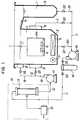
- an ultrasonic cleaning apparatus for carrying out a method of ultrasonically cleaning a workpiece has an ultrasonic cleaning tank 2 for holding a cleaning solution 1 and an overflow tank 3 disposed adjacent to the ultrasonic cleaning tank 2, the ultrasonic cleaning tank 2 and the overflow tank 3 being interconnected by an inclined discharge passage 4.
- An ultrasonic vibrator 5 is mounted on the bottom of the ultrasonic cleaning tank 2 for radiating ultrasonic energy into the cleaning solution 1 to clean workpieces 6 immersed therein.
- a heater 7 for heating the cleaning solution 1 is also mounted on the bottom of the ultrasonic cleaning tank 2.
- the ultrasonic cleaning tank 2 has a cleaning solution outlet 8 and a cleaning solution inlet 9 which are mounted on a side wall thereof in confronting relationship to each other. Each of the cleaning solution outlet 8 and the cleaning solution inlet 9 has a flow rectifying device (not shown) for smoothing a flow of cleaning solution going therethrough.
- a deaerator 10 for deaerating the cleaning solution is disposed outside of the ultrasonic cleaning tank 2.
- the deaerator 10 comprises a sealed tank 13 for holding the cleaning solution 1 therein and a vacuum pump 14 for evacuating the sealed tank 13 to discharge a dissolved gas in the cleaning solution 1 into a space within the sealed tank 13 for thereby deaerating the cleaning solution 1.
- the deaerator 10 is connected to the cleaning solution outlet 8 by a discharge conduit 11 and to the cleaning solution inlet 9 by a supply conduit 12.
- a discharge pump 15 for introducing the cleaning solution 1 discharged from the cleaning solution outlet 8 into the deaerator 10 is connected to the discharge conduit 11 upstream of the deaerator 10.
- a filter 16 is connected between the deaerator 10 and the discharge pump 15.
- a supply pump 17 for supplying the deaerated cleaning solution 1 from the deaerator 10 to the ultrasonic cleaning tank 2 is connected to the supply conduit 12 between the deaerator 10 and the cleaning solution inlet 9.
- An upper cleaning solution inlet 18 is mounted on an upper wall portion of the ultrasonic cleaning tank 2, and connected to an upper supply conduit 19 which is branched from the supply conduit 12 downstream of the supply pump 17.
- a cleaning solution discharge conduit 20 and an overflow solution discharge conduit 21 are connected to the respective bottoms of the ultrasonic cleaning tank 2 and the overflow tank 3.
- the cleaning solution discharge conduit 20 and the overflow solution discharge conduit 21 are connected to the discharge conduit 11.
- the conduits 11, 12, 19, 20, 21 have flow control valves 22.
- the cleaning solution 1 held in the ultrasonic cleaning tank 2 is a mixture of tap water and 5% of a detergent.
- the detergent comprises an aqueous solution containing 6.0% of a nonionic surface active agent, 7.0% of an inorganic builder, 10.0% of a solubilization agent, and 1.0% of others.
- the cleaning solution 1 in the ultrasonic cleaning tank 2 is drawn therefrom through the cleaning solution outlet 8 by the discharge pump 15, and introduced into the deaerator 10 through the discharge conduit 11 via the filter 16. Since the sealed tank 13 of the deaerator 10 is deaerated by the vacuum pump 14, when the cleaning solution 1 is introduced into the sealed tank 13 through the discharge conduit 11, a gas dissolved in the cleaning solution 1 is charged into the evacuated space in the sealed tank 13. At this time, the cleaning solution 1 is deaerated to such an extent that the amount of dissolved oxygen ranges from 0.01 to 5 ppm depending on the type of workpieces 6 to be cleaned. The amount of dissolved oxygen may readily be regulated depending on the type of workpieces 6 to be cleaned by varying the degree to which the sealed tank 13 is evacuated by the vacuum pump 14.
- the deaerated cleaning solution 1 is drawn from the deaerator 10 by the supply pump 17, and supplied through the supply conduit 12 and the cleaning solution inlet 9 into the ultrasonic cleaning tank 2. Since the cleaning solution 1 circulates through the ultrasonic cleaning apparatus as described above, the amount of oxygen dissolved in the cleaning solution 1 can be maintained in the above range at all times.
- the ultrasonic vibrator 5 is actuated to radiate ultrasonic energy into the cleaning solution 1 in the ultrasonic cleaning tank 2 for cleaning the workpieces 6 that are immersed in the cleaning solution 1. If the workpieces 6 are relatively small in size, then a number of workpieces 6 are placed in a container 6a of stainless steel, and the container 6a is immersed in the cleaning solution 1.
- the cleaning solution 1 in the ultrasonic cleaning tank 2 When the workpieces 6 are immersed in the cleaning solution 1 in the ultrasonic cleaning tank 2, a portion of the cleaning solution 1 overflows the ultrasonic cleaning tank 2, and introduced down the discharge passage 4 into the overflow tank 3. The cleaning solution 1 that has been introduced into the overflow tank 3 is then discharged from the overflow tank 3 through the overflow discharge conduit 21 into the discharge conduit 11. The cleaning solution 1 is supplied to and deaerated by the deaerator 10, and the deaerated cleaning solution 1 is supplied to the ultrasonic cleaning tank 2. Therefore, the surface level, the amount of dissolved oxygen, and temperature of the cleaning solution 1 in the ultrasonic cleaning tank 2 remain unchanged.
- the cleaning solution 1 on the bottom of the ultrasonic cleaning tank 2 is drawn through the cleaning solution discharge conduit 20 into the discharge conduit 11, from which the cleaning solution 1 is introduced into the deaerator 10.
- a portion of the deaerated cleaning solution 1 is supplied from the upper cleaning solution inlet 18 to the ultrasonic cleaning tank 2.
- the deaerated cleaning solution 1 supplied from the upper cleaning solution inlet 18 is effective to agitate the cleaning solution 1 in the ultrasonic cleaning tank 2 for uniformizing the temperature of the cleaning solution 1 that is heated by the heater 7.
- the cleaning solution 1 drawn from the ultrasonic cleaning tank 2 through the conduits 11, 20, 21 contains burrs and solid foreign matter removed from the work-pieces 6. These burrs and solid foreign matter are collected by the filter 16 that is positioned in the discharge conduit 11 between the discharge pump 15 and the deaerator 10.
- the ultrasonic cleaning apparatus is not required to deaerate the cleaning solution 1 to such a high extent that the amount of oxygen contained in the cleaning solution 1 is equal to or lower than 0.01 ppm.
- the deaerator 10 is capable of deaerating the cleaning solution 1 to such an extent that the amount of oxygen dissolved in the cleaning solution 1 ranges from 0.01 to 5 ppm.
- the ultrasonic cleaning apparatus does not need a highly expensive deaerator composed of a plurality of gas separating membrane modules, and hence is relatively simple in overall structure.
- a cleaning solution 1 that had been deaerated to a dissolved oxygen range from 0.01 to 0.5 ppm was supplied to the ultrasonic cleaning tank 2, and razor blades of stainless steel with small burrs having dimensions of about 100 ⁇ m were immersed as workpieces 6 in the cleaning solution 1.
- the burrs which were not completely separated from the razor blades would not have been removed in a normal cleaning process using an organic solvent.
- the razor blades were ultrasonically cleaned using the cleaning solution 1 deaerated to the above dissolved oxygen range, and the burrs as well as other foreign matter such as dust particles and material residues were removed almost completely. When the amount of dissolved oxygen was in excess of 0.5 ppm, the burrs were not fully removed from the razor blades.
- a cleaning solution 1 that had been deaerated to a dissolved oxygen content ranging from 0.01 to 3 ppm was supplied to the ultrasonic cleaning tank 2, and sintered parts with solid foreign matter such as material residues and dust particles being electrostatically attracted thereto were immersed as workpieces 6 in the cleaning solution 1.
- the sintered parts were ultrasonically cleaned in the cleaning solution 1 with the above dissolved oxygen content, the solid foreign matter such as material residues and dust particles was removed substantially completely.
- the solid foreign matter such as material residues and dust particles is not joined to the sintered parts, it may be sufficiently removed even when subjected to microjets that are not so powerful as those used to remove the burrs in the above example.
- Workpieces 6 that can effectively be cleaned by the cleaning solution 1 with a dissolved oxygen content ranging from 0.01 to 3 ppm include magnets, acupuncture needles, and piston rods as well as sintered parts. Dust particles and abrasive grain are electrostatically held in direct contact with acupuncture needles. Abrasive grain, a grinding material, and other foreign matter are held in direct contact with piston rods.
- a cleaning solution 1 that had been deaerated to a dissolved oxygen content ranging from 2 to 5 ppm was supplied to the ultrasonic cleaning tank 2, and metallic connector pins were immersed as work-pieces 6 in the cleaning solution 1.
- Solid foreign matter such as material residues including chips produced when the metallic connector pins were machined and small particles produced when burrs were broken was attached to the metallic connector pins by oil such as cutting oil used when the metallic connector pins were machined.
- the cleaning solution 1 was heated to a temperature range of from 30 to 40°C by the heater 7.
- Workpieces 6 that can effectively be cleaned by the cleaning solution 1 with a dissolved oxygen content ranging from 2 to 5 ppm include metallic parts for use in watches and clocks, pressed metallic workpieces, injection-and extrusion-molded plastic workpieces, aluminum hoops, and mechanical seals as well as connector pins.
- the cleaning solution 1 deaerated to the above dissolved oxygen content depending on the type of workpieces 6 to be cleaned is supplied to the single ultrasonic cleaning tank 2 for ultrasonically cleaning the workpieces 6.
- a plurality of ultrasonic cleaning tanks 2 may be employed, and a cleaning solution 1 deaerated to a dissolved oxygen content ranging from 2 to 5 ppm may be supplied to the first ultrasonic cleaning tank 2, and a cleaning solution 1 deaerated to a dissolved oxygen content ranging from 0.01 to 0.5 ppm may be supplied to the second ultrasonic cleaning tank 2.
- workpieces 6 of one type can be ultrasonically cleaned through a plurality of steps.
- razor blades may be ultrasonically cleaned in the first ultrasonic cleaning tank 2 to remove solid foreign matter attached to the razor blades by oil, and then ultrasonically cleaned in the second ultrasonic cleaning tank 2 to remove burrs from the razor blades.
- An ultrasonic cleaning apparatus used for experimentally ultrasonically cleaning workpieces in the experiments will be described below with reference to FIG. 2.
- An ultrasonic vibrator 5 is mounted on the bottom of an ultrasonic cleaning tank 2 of acrylic resin which holds a cleaning solution 1.
- the ultrasonic vibrator 5 radiates ultrasonic energy into the cleaning solution to clean workpieces 6 placed in a container 6a and immersed in the cleaning solution 1.
- the ultrasonic cleaning tank 2 has a cleaning solution outlet 8 and a cleaning solution inlet 9 which are mounted on a side wall thereof in confronting relationship to each other. Each of the cleaning solution outlet 8 and the cleaning solution inlet 9 has a flow rectifying device (not shown) for smoothing a flow of cleaning solution going therethrough.
- a deaerator 10, identical to the deaerator 10 shown in FIG. 1, for deaerating the cleaning solution is disposed outside of the ultrasonic cleaning tank 2.
- the deaerator 10 is connected to the cleaning solution outlet 8 by a discharge conduit 11 and to the cleaning solution inlet 9 by a supply conduit 12.
- a circulation pump 22 for introducing the cleaning solution 1 discharged from the cleaning solution outlet 8 into the deaerator 10 and supplying the deaerated cleaning solution to the ultrasonic cleaning tank 2 is connected to the discharge conduit 11 upstream of the deaerator 10.
- Filters 23a, 23b are connected between the deaerator 10 and the circulation pump 22.
- a bypass conduit 24 and a flow control valve 25 are connected to the discharge conduit 11, the bypass conduit 24 being connected between upstream and downstream sides of the circulation pump 22.
- the bypass conduit 24 can be opened and closed by a flow control valve 26 connected thereto.
- the cleaning solution 1 contained in the ultrasonic cleaning tank 2 is drawn from the cleaning solution outlet 8 into the discharge conduit 11 by the circulation pump 22, and then supplied to the filters 23a, 23b.
- the cleaning solution 1 contains burrs and foreign matter removed from the workpieces 6 by the ultrasonic cleaning process in the ultrasonic cleaning tank 2.
- the filter 23a removes relatively large burrs and foreign matter having dimensions of 5 ⁇ m or greater
- the filter 23b removes smaller burrs and foreign matter having dimensions of up to 2 ⁇ m.
- the cleaning solution 1 from the filters 23a, 23b is introduced into the deaerator 10, which deaerates the cleaning solution 1 to a desired dissolved oxygen content, and the deaerated cleaning solution 1 is supplied through the supply conduit 12 and the cleaning solution inlet 9 to the ultrasonic cleaning tank 2.
- Tap water was supplied as the cleaning solution 1 to the ultrasonic cleaning tank 2, and instead of the workpieces 6 and the container 6a, a plate of pure aluminum having dimensions of 100 mm X 100 mm X 10 mm was immersed in the cleaning solution 1 perpendicularly to the ultrasonic vibrator 5, the plate of pure aluminum having an upper edge positioned 50 mm below the surface level of the cleaning solution 1. The lower edge of the plate of pure aluminum did not reach the ultrasonic vibrator 5, and was spaced 50 mm or more from the ultrasonic vibrator 5.
- ultrasonic energy was radiated from the ultrasonic vibrator 5 into the cleaning solution 1 to produce microjets that eroded the aluminum plate.
- the aluminum plate was vertically moved a vertical distance of 25 mm for uniform exposure to the microjets.
- the amount of oxygen dissolved in the cleaning solution 1 was varied stepwise between 0.05 to 9 ppm.
- the ultrasonic cleaning process was carried out for 60 minutes with respect to each of the dissolved oxygen contents.
- the aluminum plate was pulled out, and an erosion-induced reduction in the weight of the aluminum plate was measured as being indicative of the intensity of applied microjets.
- the greater the eroded amount of aluminum the greater the reduction in the weight of the aluminum plate, indicating a greater microjet intensity.
- the weight was measured ten times for each of the dissolved oxygen contents, and the average value was used as the eroded amount of aluminum at the dissolved oxygen content.
- the cleaning solution 1 was kept at a normal temperature ranging from 20 to 25°C.
- the cleaning solution 1 was directed as a laminar flow from the cleaning solution inlet 9 to the cleaning solution outlet 8 parallel to the ultrasonic vibrator 5.
- the ultrasonic vibrator 5 radiated ultrasonic energy having an intensity of 600 W at a single frequency of 28 KHz.
- the output watt density of the ultrasonic vibrator 5 was 1 W/cm2 at maximum.
- Table 1 shows the relationship between the amount of oxygen dissolved in the cleaning solution 1 and the eroded amount of aluminum as ultrasonically cleaned.
- the intensity of microjets is maximum below the dissolved oxygen content of about 0.5 ppm, and gradually decreases to the dissolved oxygen content of about 2 ppm, and that the intensity of microjets decreases substantially linearly as the dissolved oxygen content increases until the dissolved oxygen content reaches about 6 ppm, and the eroded amount of aluminum is of a substantially constant level of 15 to 16 mg above the dissolved oxygen content of 7 ppm or higher.
- microjets have an intensity sufficient to clean the aluminum plate when the dissolved oxygen content is of about 5 ppm or lower, do not produce an effective cleaning effect when the dissolved oxygen content is higher than about 5 ppm, and produces almost no cleaning effect when the dissolved oxygen content is of 7 ppm or higher.
- a specimen was prepared by grinding opposite surfaces of an SUS plate having dimensions of 100 mm x 100 mm x 10 mm with abrasive grain and applying 10 cc of mineral machine oil to the SUS plate.
- the machine oil applied to the specimen was extracted with carbon tetrachloride, the infrared absorption ratio of the machine oil was measured five times, and the average of the measured values was used as a blank.
- the blank indicates the amount of machine oil attached to the specimen prior to ultrasonic cleaning, i.e., the initial value of machine oil attached to the specimen, and was 147.6 mg.
- a cleaning solution 1 comprising tap water and 5% of a detergent composed of a nonionic surface active agent was supplied to the ultrasonic cleaning tank 2 shown in FIG. 2, and instead of the workpieces 6 and the container 6a, the above specimen was immersed in the cleaning solution 1 perpendicularly to the ultrasonic vibrator 5, the specimen having an upper edge positioned 50 mm below the surface level of the cleaning solution 1. The lower edge of the plate of pure aluminum did not reach the ultrasonic vibrator 5, and was spaced 50 mm or more from the ultrasonic vibrator 5.
- the amount of oxygen dissolved in the cleaning solution 1 was varied stepwise between 0.05 to 9 ppm.
- the ultrasonic cleaning process was carried out for 60 minutes with respect to each of the dissolved oxygen contents. After each ultrasonic cleaning process, the specimen was pulled out, and hot air was applied directly to the specimen to dry the same at a temperature of 80°C for 60 seconds. After the specimen was dried, the machine oil attached to the specimen was extracted with carbon tetrachloride, the infrared absorption ratio of the machine oil was measured five times for each of the dissolved oxygen contents, and the average of the measured values was used as an amount of oil attached after the ultrasonic cleaning. The differences between the above blanks and the amounts of oil attached after the ultrasonic cleaning were determined to calculate the amounts of oil removed after the ultra sonic cleaning.
- Table 2 shows the relationship between the amount of oxygen dissolved in the cleaning solution 1 and the amount of oil removed by the ultrasonic cleaning.
- the amount of oil removed after the cleaning blank (147.6) - the amount of oil attached after the cleaning.
- the amount of oil removed is small when the amount of oxygen dissolved in the cleaning solution 1 is less than 2 ppm, and increases as the amount of dissolved oxygen increases.
- the ultrasonic cleaning apparatus shown in FIG. 2 is practical enough to be effective for use as a tabletop ultrasonic cleaning apparatus for cleaning small parts as well as an experimental ultrasonic cleaning apparatus.
Landscapes
- Cleaning By Liquid Or Steam (AREA)
- Cleaning And De-Greasing Of Metallic Materials By Chemical Methods (AREA)
Applications Claiming Priority (4)
| Application Number | Priority Date | Filing Date | Title |
|---|---|---|---|
| JP41510/92U | 1992-05-25 | ||
| JP4151092U JPH0634783U (ja) | 1992-05-25 | 1992-05-25 | ワークの洗浄、バリ取り装置における脱気装置 |
| JP239384/92 | 1992-09-08 | ||
| JP4239384A JPH0688265A (ja) | 1992-09-08 | 1992-09-08 | 超音波洗浄装置 |
Publications (2)
| Publication Number | Publication Date |
|---|---|
| EP0572211A1 true EP0572211A1 (fr) | 1993-12-01 |
| EP0572211B1 EP0572211B1 (fr) | 1997-03-12 |
Family
ID=26381151
Family Applications (1)
| Application Number | Title | Priority Date | Filing Date |
|---|---|---|---|
| EP93304034A Expired - Lifetime EP0572211B1 (fr) | 1992-05-25 | 1993-05-25 | Méthode de nettoyage ultra-sonique d'une pièce |
Country Status (9)
| Country | Link |
|---|---|
| US (1) | US6059886A (fr) |
| EP (1) | EP0572211B1 (fr) |
| KR (1) | KR930023072A (fr) |
| CN (1) | CN1054082C (fr) |
| CA (1) | CA2096589C (fr) |
| DE (1) | DE69308638T2 (fr) |
| MY (1) | MY109820A (fr) |
| SG (1) | SG47956A1 (fr) |
| TW (1) | TW212146B (fr) |
Cited By (2)
| Publication number | Priority date | Publication date | Assignee | Title |
|---|---|---|---|---|
| EP0810643A3 (fr) * | 1996-05-28 | 1998-03-11 | Canon Kabushiki Kaisha | Méthode de nettoyage d'une surface poreuse d'un substrat semiconducteur |
| US6058945A (en) * | 1996-05-28 | 2000-05-09 | Canon Kabushiki Kaisha | Cleaning methods of porous surface and semiconductor surface |
Families Citing this family (29)
| Publication number | Priority date | Publication date | Assignee | Title |
|---|---|---|---|---|
| JP2996334B2 (ja) * | 1994-03-30 | 1999-12-27 | 東北日本電気株式会社 | 超音波脱脂装置 |
| JPH11333215A (ja) * | 1998-05-29 | 1999-12-07 | Lsi Logic Corp | ろ過フィルターのエアーロック防止装置 |
| US6699400B1 (en) * | 1999-06-04 | 2004-03-02 | Arne W. Ballantine | Etch process and apparatus therefor |
| JP3901979B2 (ja) * | 2001-10-12 | 2007-04-04 | ミネベア株式会社 | 硫黄快削合金鋼の処理方法 |
| WO2005061131A1 (fr) * | 2003-12-23 | 2005-07-07 | The Australian National University | Nettoyage a base d'eau |
| CN1958872B (zh) * | 2006-10-12 | 2010-05-26 | 武汉科利尔化工有限公司 | 回收工件、夹具所带电镀液的方法 |
| US7823272B2 (en) * | 2006-11-14 | 2010-11-02 | The Gillette Company | Systems for producing assemblies |
| US7682457B2 (en) * | 2007-10-04 | 2010-03-23 | Applied Materials, Inc. | Frontside structure damage protected megasonics clean |
| JP5329352B2 (ja) * | 2009-09-08 | 2013-10-30 | 東京エレクトロン株式会社 | 超音波洗浄装置、超音波洗浄方法、およびこの超音波洗浄方法を実行するためのコンピュータプログラムが記録された記録媒体 |
| CN102108517A (zh) * | 2009-12-29 | 2011-06-29 | 中原工学院 | 一种金属烧结网的清洗工艺及其装置 |
| CN102553852A (zh) * | 2010-12-28 | 2012-07-11 | 北京京东方光电科技有限公司 | 清洗装置 |
| CN102708875A (zh) * | 2011-03-28 | 2012-10-03 | 东莞新科技术研究开发有限公司 | 真空清洗方法 |
| CN102698977A (zh) * | 2011-03-28 | 2012-10-03 | 东莞新科技术研究开发有限公司 | 真空清洗装置 |
| CN102357489A (zh) * | 2011-11-15 | 2012-02-22 | 天龙科技炉业(无锡)有限公司 | 超声波真空节能清洗机 |
| CN102489469B (zh) * | 2011-11-23 | 2014-07-09 | 由田信息技术(上海)有限公司 | 使用超声波震荡液体以清洁基板的方法 |
| CN103894367A (zh) * | 2012-12-28 | 2014-07-02 | 赫菲斯热处理系统江苏有限公司 | 一种热处理生产线用真空清洗机 |
| CN103894366A (zh) * | 2012-12-28 | 2014-07-02 | 赫菲斯热处理系统江苏有限公司 | 一种真空清洗室 |
| CN104084396A (zh) * | 2014-07-14 | 2014-10-08 | 苏州金牛精密机械有限公司 | 一种工件清洗槽 |
| WO2016038679A1 (fr) * | 2014-09-09 | 2016-03-17 | 株式会社ブルー・スターR&D | Dispositif ultrasonore de suppression de bavures |
| US9808840B2 (en) * | 2014-10-15 | 2017-11-07 | Saudi Arabian Oil Company | Air filter ultrasonic cleaning systems and the methods of using the same |
| CN105643375B (zh) * | 2016-01-12 | 2018-08-17 | 中国石油大学(华东) | 一种高声能密度单槽真空混频浸没式超声波表面处理装置 |
| CN109107981A (zh) * | 2017-06-23 | 2019-01-01 | 黄鹤洋 | 一种医用超声波清洗装置 |
| CN107803364A (zh) * | 2017-11-20 | 2018-03-16 | 嘉善信息技术工程学校 | 一种剃须刀清理设备 |
| JP7131622B2 (ja) * | 2018-09-26 | 2022-09-06 | 日本製鉄株式会社 | 金属管の洗浄方法及び洗浄装置 |
| CN110238540A (zh) * | 2019-05-31 | 2019-09-17 | 苏州五方光电材料有限公司 | 一种光学镜片的加工方法 |
| CN114101197A (zh) * | 2021-07-09 | 2022-03-01 | 内蒙古久科康瑞环保科技有限公司 | 石油压裂支撑剂清洗筛分装置 |
| CN114669549A (zh) * | 2022-03-08 | 2022-06-28 | 阳江合金材料实验室 | 一种避免刀具空化腐蚀的清洗方法及系统 |
| CN115572964A (zh) * | 2022-11-21 | 2023-01-06 | 河北宇天材料科技有限公司 | 一种铝合金腔体导电氧化处理方法 |
| CN116586365A (zh) * | 2023-05-23 | 2023-08-15 | 中国地质大学(武汉) | 一种铸件内腔高效清理与清洁度检测一体化方法 |
Citations (3)
| Publication number | Priority date | Publication date | Assignee | Title |
|---|---|---|---|---|
| US2977962A (en) * | 1957-12-11 | 1961-04-04 | Zucker Jacques | Process for the cleaning of metal parts |
| US4193818A (en) * | 1978-05-05 | 1980-03-18 | American Sterilizer Company | Combined ultrasonic cleaning and biocidal treatment in a single pressure vessel |
| US4907611A (en) * | 1986-12-22 | 1990-03-13 | S & C Co., Ltd. | Ultrasonic washing apparatus |
Family Cites Families (7)
| Publication number | Priority date | Publication date | Assignee | Title |
|---|---|---|---|---|
| US2997962A (en) * | 1958-05-08 | 1961-08-29 | Gen Motors Corp | Pump |
| JP2794438B2 (ja) * | 1989-02-16 | 1998-09-03 | 本多電子株式会社 | キャビテーションを利用した洗浄方法 |
| JP2744913B2 (ja) * | 1989-03-06 | 1998-04-28 | エスアンドシー株式会社 | 超音波洗浄、バリ取り装置 |
| JPH03288581A (ja) * | 1990-04-03 | 1991-12-18 | Yoshihide Shibano | スプレー式超音波洗浄装置 |
| JPH0424552A (ja) * | 1990-05-21 | 1992-01-28 | Tosoh Corp | ヒドロキノン誘導体の分析方法 |
| US5202523A (en) * | 1991-07-29 | 1993-04-13 | Grossman Dennis L | Firearm cleaning system |
| US5201958A (en) * | 1991-11-12 | 1993-04-13 | Electronic Controls Design, Inc. | Closed-loop dual-cycle printed circuit board cleaning apparatus and method |
-
1993
- 1993-05-01 TW TW082103406A patent/TW212146B/zh active
- 1993-05-19 CA CA002096589A patent/CA2096589C/fr not_active Expired - Fee Related
- 1993-05-21 MY MYPI93000963A patent/MY109820A/en unknown
- 1993-05-24 KR KR1019930008940A patent/KR930023072A/ko not_active Withdrawn
- 1993-05-25 DE DE69308638T patent/DE69308638T2/de not_active Expired - Fee Related
- 1993-05-25 CN CN93106226A patent/CN1054082C/zh not_active Expired - Fee Related
- 1993-05-25 US US08/066,994 patent/US6059886A/en not_active Expired - Fee Related
- 1993-05-25 SG SG1996005650A patent/SG47956A1/en unknown
- 1993-05-25 EP EP93304034A patent/EP0572211B1/fr not_active Expired - Lifetime
Patent Citations (3)
| Publication number | Priority date | Publication date | Assignee | Title |
|---|---|---|---|---|
| US2977962A (en) * | 1957-12-11 | 1961-04-04 | Zucker Jacques | Process for the cleaning of metal parts |
| US4193818A (en) * | 1978-05-05 | 1980-03-18 | American Sterilizer Company | Combined ultrasonic cleaning and biocidal treatment in a single pressure vessel |
| US4907611A (en) * | 1986-12-22 | 1990-03-13 | S & C Co., Ltd. | Ultrasonic washing apparatus |
Non-Patent Citations (1)
| Title |
|---|
| PATENT ABSTRACTS OF JAPAN vol. 016, no. 186 (P-1347)7 May 1992 & JP-A-04 024552 ( TOSOH CORP. ) 28 January 1992 * |
Cited By (3)
| Publication number | Priority date | Publication date | Assignee | Title |
|---|---|---|---|---|
| EP0810643A3 (fr) * | 1996-05-28 | 1998-03-11 | Canon Kabushiki Kaisha | Méthode de nettoyage d'une surface poreuse d'un substrat semiconducteur |
| US6058945A (en) * | 1996-05-28 | 2000-05-09 | Canon Kabushiki Kaisha | Cleaning methods of porous surface and semiconductor surface |
| KR100370312B1 (ko) * | 1996-05-28 | 2003-04-10 | 캐논 가부시끼가이샤 | 다공질표면및반도체표면의세정방법 |
Also Published As
| Publication number | Publication date |
|---|---|
| CA2096589A1 (fr) | 1993-11-26 |
| DE69308638T2 (de) | 1997-10-02 |
| CN1079679A (zh) | 1993-12-22 |
| EP0572211B1 (fr) | 1997-03-12 |
| CA2096589C (fr) | 2000-12-26 |
| DE69308638D1 (de) | 1997-04-17 |
| SG47956A1 (en) | 1998-04-17 |
| KR930023072A (ko) | 1993-12-18 |
| CN1054082C (zh) | 2000-07-05 |
| MY109820A (en) | 1997-08-30 |
| TW212146B (en) | 1993-09-01 |
| US6059886A (en) | 2000-05-09 |
Similar Documents
| Publication | Publication Date | Title |
|---|---|---|
| CA2096589C (fr) | Methode de nettoyage par ultrasons d'une piece a usiner | |
| JP2922791B2 (ja) | 液化ガスを使用した安価な洗浄装置 | |
| EP0648548B1 (fr) | Méthode et appareil pour nettoyer | |
| TW490757B (en) | Apparatus for providing ozonated process fluid and methods for using same | |
| JPH11505175A (ja) | 除泡装置 | |
| JPH0638120B2 (ja) | 放射性物質で汚染された部分を除染するための方法及び装置 | |
| JPH06254520A (ja) | 液化ガス内でのキャビテーションによる洗浄 | |
| US4057070A (en) | Cleaning apparatus for mechanical workpieces | |
| JPH11507121A (ja) | 基板を乾燥する方法及び装置 | |
| RU2124551C1 (ru) | Способ очистки трансформаторных масел и гидрожидкостей от воды и растворенных газов и устройство для его осуществления | |
| US4305413A (en) | Cleaning apparatus | |
| US5820688A (en) | Method for the treatment of semiconductor material | |
| CN1125963C (zh) | 改进的化学干燥和净化系统 | |
| JP2857054B2 (ja) | 圧縮され凝縮されたケースを使用したメガソニック洗浄システム | |
| EP1408534B1 (fr) | Procédé et dispositif pour la fabrication d'une surface adhésive d'un substrat | |
| JPH0688265A (ja) | 超音波洗浄装置 | |
| GB2237504A (en) | Ultrasonic cleaning | |
| JPH07185486A (ja) | 超音波洗浄方法 | |
| JPH03231427A (ja) | 板状体の洗浄方法 | |
| RU2009864C1 (ru) | Способ струйной обработки | |
| EP0576296B1 (fr) | Procédé de traitement de surface d'une pièce | |
| JP2512342Y2 (ja) | 超音波洗浄、バリ取り装置 | |
| JPH0910468A (ja) | 布製品の超音波洗浄方法 | |
| RU2847904C1 (ru) | Способ дезактивации радиоактивных отходов струей жидкости | |
| JPH01189127A (ja) | ウエハの洗浄方法 |
Legal Events
| Date | Code | Title | Description |
|---|---|---|---|
| PUAI | Public reference made under article 153(3) epc to a published international application that has entered the european phase |
Free format text: ORIGINAL CODE: 0009012 |
|
| AK | Designated contracting states |
Kind code of ref document: A1 Designated state(s): BE DE ES FR GB LU NL SE |
|
| 17P | Request for examination filed |
Effective date: 19940509 |
|
| 17Q | First examination report despatched |
Effective date: 19941209 |
|
| GRAG | Despatch of communication of intention to grant |
Free format text: ORIGINAL CODE: EPIDOS AGRA |
|
| GRAH | Despatch of communication of intention to grant a patent |
Free format text: ORIGINAL CODE: EPIDOS IGRA |
|
| GRAH | Despatch of communication of intention to grant a patent |
Free format text: ORIGINAL CODE: EPIDOS IGRA |
|
| GRAA | (expected) grant |
Free format text: ORIGINAL CODE: 0009210 |
|
| AK | Designated contracting states |
Kind code of ref document: B1 Designated state(s): BE DE ES FR GB LU NL SE |
|
| PG25 | Lapsed in a contracting state [announced via postgrant information from national office to epo] |
Ref country code: NL Free format text: LAPSE BECAUSE OF FAILURE TO SUBMIT A TRANSLATION OF THE DESCRIPTION OR TO PAY THE FEE WITHIN THE PRESCRIBED TIME-LIMIT Effective date: 19970312 Ref country code: ES Free format text: THE PATENT HAS BEEN ANNULLED BY A DECISION OF A NATIONAL AUTHORITY Effective date: 19970312 Ref country code: BE Effective date: 19970312 |
|
| REF | Corresponds to: |
Ref document number: 69308638 Country of ref document: DE Date of ref document: 19970417 |
|
| PG25 | Lapsed in a contracting state [announced via postgrant information from national office to epo] |
Ref country code: LU Free format text: LAPSE BECAUSE OF NON-PAYMENT OF DUE FEES Effective date: 19970525 |
|
| ET | Fr: translation filed | ||
| NLV1 | Nl: lapsed or annulled due to failure to fulfill the requirements of art. 29p and 29m of the patents act | ||
| REG | Reference to a national code |
Ref country code: GB Ref legal event code: 732E |
|
| PLBE | No opposition filed within time limit |
Free format text: ORIGINAL CODE: 0009261 |
|
| STAA | Information on the status of an ep patent application or granted ep patent |
Free format text: STATUS: NO OPPOSITION FILED WITHIN TIME LIMIT |
|
| REG | Reference to a national code |
Ref country code: FR Ref legal event code: TP |
|
| 26N | No opposition filed | ||
| PGFP | Annual fee paid to national office [announced via postgrant information from national office to epo] |
Ref country code: SE Payment date: 19980507 Year of fee payment: 6 |
|
| PGFP | Annual fee paid to national office [announced via postgrant information from national office to epo] |
Ref country code: FR Payment date: 19980520 Year of fee payment: 6 |
|
| PGFP | Annual fee paid to national office [announced via postgrant information from national office to epo] |
Ref country code: GB Payment date: 19980521 Year of fee payment: 6 |
|
| PG25 | Lapsed in a contracting state [announced via postgrant information from national office to epo] |
Ref country code: GB Free format text: LAPSE BECAUSE OF NON-PAYMENT OF DUE FEES Effective date: 19990525 |
|
| PG25 | Lapsed in a contracting state [announced via postgrant information from national office to epo] |
Ref country code: SE Free format text: LAPSE BECAUSE OF NON-PAYMENT OF DUE FEES Effective date: 19990526 |
|
| GBPC | Gb: european patent ceased through non-payment of renewal fee |
Effective date: 19990525 |
|
| EUG | Se: european patent has lapsed |
Ref document number: 93304034.7 |
|
| PG25 | Lapsed in a contracting state [announced via postgrant information from national office to epo] |
Ref country code: FR Free format text: LAPSE BECAUSE OF NON-PAYMENT OF DUE FEES Effective date: 20000131 |
|
| REG | Reference to a national code |
Ref country code: FR Ref legal event code: ST |
|
| PGFP | Annual fee paid to national office [announced via postgrant information from national office to epo] |
Ref country code: DE Payment date: 20000703 Year of fee payment: 8 |
|
| PG25 | Lapsed in a contracting state [announced via postgrant information from national office to epo] |
Ref country code: DE Free format text: LAPSE BECAUSE OF NON-PAYMENT OF DUE FEES Effective date: 20020301 |