EP0581265A2 - Tête magnétique composite - Google Patents
Tête magnétique composite Download PDFInfo
- Publication number
- EP0581265A2 EP0581265A2 EP93112061A EP93112061A EP0581265A2 EP 0581265 A2 EP0581265 A2 EP 0581265A2 EP 93112061 A EP93112061 A EP 93112061A EP 93112061 A EP93112061 A EP 93112061A EP 0581265 A2 EP0581265 A2 EP 0581265A2
- Authority
- EP
- European Patent Office
- Prior art keywords
- head
- magnetic
- digital signal
- head chip
- analog signal
- Prior art date
- Legal status (The legal status is an assumption and is not a legal conclusion. Google has not performed a legal analysis and makes no representation as to the accuracy of the status listed.)
- Withdrawn
Links
Images


Classifications
-
- G—PHYSICS
- G11—INFORMATION STORAGE
- G11B—INFORMATION STORAGE BASED ON RELATIVE MOVEMENT BETWEEN RECORD CARRIER AND TRANSDUCER
- G11B5/00—Recording by magnetisation or demagnetisation of a record carrier; Reproducing by magnetic means; Record carriers therefor
- G11B5/127—Structure or manufacture of heads, e.g. inductive
- G11B5/33—Structure or manufacture of flux-sensitive heads, i.e. for reproduction only; Combination of such heads with means for recording or erasing only
- G11B5/39—Structure or manufacture of flux-sensitive heads, i.e. for reproduction only; Combination of such heads with means for recording or erasing only using magneto-resistive devices or effects
- G11B5/3903—Structure or manufacture of flux-sensitive heads, i.e. for reproduction only; Combination of such heads with means for recording or erasing only using magneto-resistive devices or effects using magnetic thin film layers or their effects, the films being part of integrated structures
- G11B5/3967—Composite structural arrangements of transducers, e.g. inductive write and magnetoresistive read
-
- G—PHYSICS
- G11—INFORMATION STORAGE
- G11B—INFORMATION STORAGE BASED ON RELATIVE MOVEMENT BETWEEN RECORD CARRIER AND TRANSDUCER
- G11B5/00—Recording by magnetisation or demagnetisation of a record carrier; Reproducing by magnetic means; Record carriers therefor
- G11B5/008—Recording on, or reproducing or erasing from, magnetic tapes, sheets, e.g. cards, or wires
- G11B5/00813—Recording on, or reproducing or erasing from, magnetic tapes, sheets, e.g. cards, or wires magnetic tapes
- G11B5/00878—Recording on, or reproducing or erasing from, magnetic tapes, sheets, e.g. cards, or wires magnetic tapes transducing different track configurations or formats on the same tape
-
- G—PHYSICS
- G11—INFORMATION STORAGE
- G11B—INFORMATION STORAGE BASED ON RELATIVE MOVEMENT BETWEEN RECORD CARRIER AND TRANSDUCER
- G11B5/00—Recording by magnetisation or demagnetisation of a record carrier; Reproducing by magnetic means; Record carriers therefor
- G11B5/10—Structure or manufacture of housings or shields for heads
- G11B5/105—Mounting of head within housing or assembling of head and housing
-
- G—PHYSICS
- G11—INFORMATION STORAGE
- G11B—INFORMATION STORAGE BASED ON RELATIVE MOVEMENT BETWEEN RECORD CARRIER AND TRANSDUCER
- G11B5/00—Recording by magnetisation or demagnetisation of a record carrier; Reproducing by magnetic means; Record carriers therefor
- G11B5/48—Disposition or mounting of heads or head supports relative to record carriers ; arrangements of heads, e.g. for scanning the record carrier to increase the relative speed
- G11B5/488—Disposition of heads
-
- G—PHYSICS
- G11—INFORMATION STORAGE
- G11B—INFORMATION STORAGE BASED ON RELATIVE MOVEMENT BETWEEN RECORD CARRIER AND TRANSDUCER
- G11B5/00—Recording by magnetisation or demagnetisation of a record carrier; Reproducing by magnetic means; Record carriers therefor
- G11B5/48—Disposition or mounting of heads or head supports relative to record carriers ; arrangements of heads, e.g. for scanning the record carrier to increase the relative speed
- G11B5/488—Disposition of heads
- G11B5/4893—Disposition of heads relative to moving tape
Definitions
- the present invention relates to composite magnetic heads, and more particularly, to a composite magnetic head including a magnetic head which can reproduce or record/reproduce an analog signal and a magnetic head which can reproduce or record/reproduce a digital signal, used in a magnetic recording apparatus such as a DAT (Digital Audio Taperecorder), a DCC (Digital Compact Cassette), and a data memory device.
- a magnetic recording apparatus such as a DAT (Digital Audio Taperecorder), a DCC (Digital Compact Cassette), and a data memory device.
- a magnetic recording/reproducing system using a compact cassette is the mainstream.
- at most four magnetic heads may be disposed within a width of a recording medium (magnetic tape) of 3.8mm. Therefore, since a cost of the system can be more easily reduced by using the conventional bulk head than by applying the thin film magnetic head, the bulk head is currently used in the recording/reproducing system of an analog signal.
- the DCC was proposed recently by Philips Corporation, a magnetic head having an electromagnetic transformation function which can carry out both digital signal processing and analog signal processing by using a compact cassette has rapidly been developed.
- a magnetic head it is necessary to use a thin film magnetic head because of the above-described reasons when the digital signal processing is mainly taken into consideration. Therefore, the mainstream is using a head having a head for digital signal processing and a head for analog signal processing formed of a thin film material on the same substrate, in order to process an analog signal by the thin film magnetic head.
- Such a conventional combined magnetic head has a structure as shown in, for example, Fig. 8.
- the composite magnetic head shown in Fig. 8 is provided with a head chip 25 between a pair of tape guides 18, 18 of a case 17 drawn to an external circuit by a flexible print substrate 6.
- Head chip 25 is provided with a digital signal head gathering portion 23 of a thin film magnetic head group recording/reproducing a digital signal and a thin film magnetic head 24 for an analog signal recording/reproducing an analog signal formed in parallel so as to be lined up in the direction of width of a recording medium.
- digital signal head gathering portion 23 has nine cores disposed within a width approximately half that of the recording medium, while thin film magnetic head 24 for an analog signal has only two cores disposed within the same width. More specifically, since the thin film magnetic head for an analog signal occupies more space than required, the yield of magnetic head chips per wafer is decreased. Therefore, the greatest characteristic of the thin film magnetic head that highly integrated magnetic heads can be mass-produced cannot be taken full advantage of.
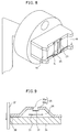
- a yoke type magnetoresistance effect type head (hereinafter referred to as a "YMR head") as shown in Fig. 9 is the mainstream.
- the YMR type head has a lower side yoke 34 forming a magnetic path, and an upper side yoke 35 divided into front and back portions. Between upper side yoke 35 and lower side yoke 34, disposed are a magnetoresistive effect element (hereinafter referred to as an "MR element”) 31 and a bias electrode 33 with an insulating layer 36 interposed therebetween.
- MR element magnetoresistive effect element
- Magnetic flux generated from a magnetic recording medium 37 is introduced into a magnetic circuit constituted of upper side yoke 35 and lower side yoke 34 in a gap portion 38 between upper side yoke 35 and lower side yoke 34. More specifically, after reaching a cutting portion of an upper side front yoke 35a, the magnetic flux passes through MR element 31 to enter upper side yoke 35 from a cutting portion of an upper side back yoke 35b. Then, the magnetic flux returns to magnetic recording medium 37 through lower side yoke 34.
- Lower side yoke 34 also serving as a substrate of the thin film magnetic head, is formed of a soft magnetic material such as ferrite. Such a thin film magnetic head has the following advantages over the conventional bulk head.
- the conventional bulk head is based on the principle that a time change of the flux led by a yoke corresponding to a signal is taken out as a voltage induced by a coil.
- the yoke type thin film magnetic head can detect a change of the flux led by the yoke directly as a resistance change of MR element 31. Therefore, a phenomenon will not occur that, as the relative speed of the tape and the head decreases, the output of the signal reproduced by the head is decreased, as seen in the conventional bulk head. As a result, at the time of traveling of the recording medium at a low speed, it is possible to obtain a sufficient reproduction sensitivity.
- the yoke type magnetoresistive effect type head is used as a reproducing head for an analog signal
- problems When a musical tone, for example, is recorded/reproduced with an analog signal, the height and magnitude of sound are directly converted from an electric signal to a magnetic signal. Therefore, when such a signal is reproduced by the yoke type thin film magnetic head, there is an unusual case where even a noise, which would not cause any problems in reproduction of a digital signal which requires only distinction between 0 and 1, gives a sense of incongruity in hearing to a listener due to a high sensitivity.
- One object of the present invention is to provide a magnetic head having a function of processing both a digital signal and an analog signal by one head, by selecting a thin film multichannel head for reproducing or recording/reproducing a digital signal and a conventional bulk head for reproducing or recording/reproducing an analog signal depending on their functions and integrating the same.
- the composite magnetic head according to the present invention which accomplishes the above object includes a head chip for an analog signal including a magnetic head reproducing or recording/reproducing an analog signal in slidable contact with a traveling magnetic recording medium, and a head chip for digital signal including a magnetic head reproducing or recording/reproducing a digital signal.
- a head chip for an analog signal including a magnetic head reproducing or recording/reproducing an analog signal in slidable contact with a traveling magnetic recording medium
- a head chip for digital signal including a magnetic head reproducing or recording/reproducing a digital signal.
- two kinds of head chips individually formed by different processes are combined into an integrated magnetic head. It is possible to use one head chip as a head chip for an analog signal, and the other head chip as a head chip for a digital signal head chip.
- the magnetic head included in the analog signal head chip includes a magnetic flux induction core of a soft magnetic bulk material with high permeability and a coil wound around the magnetic flux induction core.
- the magnetic head included in the digital signal head chip includes a reproducing head having a magnetic flux induction core of a soft magnetic thin film material with high permeability formed on the main surface of the substrate and a magnetoresistive effect element.
- the structure by using a so-called bulk type head as a head for processing an analog signal, it is possible to make the size of the head chip approximately half as compared to the case of a head of a thin film material. Therefore, it is possible to make approximately two times the number of analog signal head chips taken per one wafer. In addition, since the manufacturing cost of the bulk head is substantially lower than that of the thin film head, it is possible to reduce the total cost of the magnetic head. Moreover, by using a bulk head for analog signal processing, the problem does not occur that a noise at the time of reproduction of a musical tone tape causes a sense of incongruity in hearing, which is peculiar to the case where the thin film head is used for processing an analog signal.
- the magnetic head included in the digital signal head chip has a recording head formed on the same substrate as that of the reproducing head, whereby it is possible to carry out not only reproduction but also recording of a digital signal.
- the analog signal head chip and the digital signal head chip may be arranged so as to line up in a traveling direction of the magnetic recording medium, or may be arranged so as to line up in a direction orthogonal to the traveling direction of the magnetic recording medium. By being arranged so as to line up in the traveling direction of the magnetic recording medium, these chips can be applied to a magnetic recording/reproducing apparatus of a system which can carry out recording/reproducing of both a digital signal and an analog signal in the entire width of the magnetic recording medium.
- the analog signal head chip and the digital signal head chip can be applied to a magnetic recording/reproducing apparatus of a system in which the width of the magnetic recording medium is divided into a track region for recording/reproducing an analog signal and a track region for recording/reproducing a digital signal.
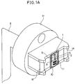
- Fig. 1A is a perspective view showing a composite magnetic head of a first embodiment of the present invention
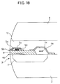
- Fig. 1B is an enlarged cross sectional view of a head for recording/reproducing a digital signal of the composite magnetic head.
- Fig. 2 is a schematic diagram showing a method of adjusting a mounting position of a magnetic head with respect to a case.
- Fig. 3 is a schematic diagram showing a method of drawing a lead from the composite magnetic head.
- Fig. 4 is a perspective view showing a composite magnetic head of a second embodiment of the present invention.
- Fig. 5 is perspective view showing a composite magnetic head of a third embodiment of the present invention.
- Fig. 6 is a cross sectional view of a core of a bulk head used in the composite magnetic head of the third embodiment shown in Fig. 5.
- Fig. 7 is a perspective view of a composite magnetic head of a fourth embodiment of the present invention.
- Fig. 8 is a perspective view showing a conventional composite magnetic head having a recording/reproducing function of both an analog signal and a digital signal.
- Fig. 9 is a cross sectional view showing an example of a yoke type magnetoresistive effective type thin film magnetic head.
- the composite magnetic head of the first embodiment based on the present invention includes a thin film magnetic head chip 1 for a digital signal, and a head chip 10 for an analog signal including a conventional bulk head for an analog signal, as shown in Fig. 1A.
- Thin film magnetic head chip 1 and head chip 10 are arranged so as to line up in a direction orthogonal to the traveling direction of a magnetic recording medium (not shown) on a magnetic recording medium traveling portion 18 to be integrated.
- thin film magnetic head 1 for processing a digital signal has a plurality of digital signal recording heads 4 and reproducing heads 5 of the same number formed on a substrate 2 of Mn-Zn ferrite or Ni-Zn ferrite.
- thin film magnetic head chip 1 as shown in Fig.
- a yoke 4a of recording head 4 and a yoke 5a of reproducing head 5 are formed on substrate 2 with a mold glass 7 and a shared core 8 interposed therebetween.
- Shared core 8 constitutes a recording magnetic circuit together with substrate 2 of a magnetic substance and yoke 4a.
- a recording gap 4b is formed at magnetic recording medium sliding surface 3 between common core 8 and substrate 2.
- Common core 8 constitutes a reproducing magnetic circuit together with a yoke 5a.
- a reproducing magnetic gap 5b is formed between common core 8 and yoke 5a.
- a recording coil 4c is provided inside yoke 4a, and an MR element 5c and a bias electrode 5d are provided inside yoke 5a.
- Yoke 4a and yoke 5a are covered with a planarized non-magnetic protecting film 12.
- a non-magnetic protecting plate 9 is affixed to the upper surface of non-magnetic protecting film 12. As described above, the thin film magnetic head is interposed between substrate 2 of a magnetic substance and non-magnetic protecting plate 9.
- an Fe-Al-Si film and an Ni-Fe film are used, respectively.
- an SiO2 film is used, and as for protecting plate 9, a CaTiO3 system ceramic substrate is used. These materials are only examples of combination.
- an amorphous alloy such as Co-Nb-Zr and metal alloy such as Fe-C, Fe-N system materials can be used other than the above.
- a lead is drawn to an external circuit by flexible print substrate 6 by applying a TAB (Tape Automated Bonding) method.
- Head chip 10 for processing an analog signal includes a conventional bulk head.
- the bulk head is formed by winding a coil around a core having thin strips 11 of permalloy in stack (not shown).
- the bulk head is resin molded at a predetermined position in a shield case (not shown).
- Other soft magnetic materials can be used as a material of the core.
- Magnetic recording medium sliding surfaces of head chips 1, 10 are processed in advance to have the same radius of coverture by cylindrical grinding and tape lapping. The radius of coverture is set to, for example, 5.0 ⁇ 0.1mm.
- head chips 1 and 10 are pressed against a reference surface 13 using optical flat arranged so as to oppose to a magnetic tape sliding surfaces of head chips 1 and 10.
- a dark and light stripes due to the light interference effect between reference surface 13 and the magnetic tape sliding surfaces of head chips 1, 10 and the relative position are monitored by a microscope.
- a parallelism (more specifically, parallelism between the magnetic surface of a tape and a tape sliding surface of the head) and projection, an azimuth with respect to a tape edge and a track position of the magnetic head included in two head chips 1, 10 are thus adjusted.
- an instantaneous adhesive agent a resin hardened by ultraviolet rays or the like, head chips 1, 10 are jointly bonded.
- Inner leads 14a of a flexible print substrate 14 are integrally connected to a pad (not shown) provided at thin film magnetic head chip 1 by the TAB method.
- Flexible print substrate 6 is connected to outer leads 14b of flexible print substrate 14 by soldering.
- a lead connecting terminal 16 of head chip 10 is connected to a terminal 15 provided at flexible print substrate 6. As described above, drawing of leads to the external circuit from two head chips 1, 10 is integrally carried out by two flexible print substrates 6, 14.
- the magnetic head integrated by such a process has the tape sliding surfaces of head chips 1, 10 and a tape sliding surface of tape guides 18a, 18b of case 17 polished by using a lapping tape, whereby the magnetic head of this embodiment is completed.
- the purpose of carrying out polishing with a lapping tape is to remove a subtle step on a joining surface between head chip 1 and head chip 10, and to finish the surface of tape guides 18a, 18b in a desired roughness.
- Case 17 is formed of a reinforced plastic having wear-resistance including carbon or fluorine. Case 17 is integrally formed by integral injection molding.
- head chips 1, 10 are integrated after finishing in advance the tape sliding surface of each of thin film magnetic head chip 1 for a digital signal and head chip 10 for an analog signal by cylindrical grinding and tape lapping.
- head chips 1, 10 are integrated in the state before applying a finishing process to the tape sliding surfaces.
- Fig. 4 shows the state where head chips 1, 10 having a tape sliding surface to which the finishing process is not applied are integrated. Adjustment of the relative position in integrating two head chips 1, 10 is carried out by using position markers 19, 20 formed on a surface serving as tape sliding surfaces of head chips 1, 10. After adjusting the relative position by position markers 19, 20, head chips 1, 10 are adhered by an instantaneous adhesive agent, a resin hardened by ultraviolet rays or the like. After that, cylindrical grinding and tape lapping are applied integrally to the tape sliding surfaces of head chips 1, 10.
- thin film magnetic head chip 1 for a digital signal thin film magnetic head chip 1 for a digital signal
- conventional bulk head chip 10 for an analog signal and a spacer 21 are integrated by a position adjusting method shown in Fig. 2.
- This embodiment is different from the first embodiment in the following points.
- a core of a shape in combination of an I type core 22 and a C type core 23 is used as a bulk head included in head chip 10 for an analog signal. It is for improving a contact state with the magnetic tape by reducing a space between a magnetic gap of a magnetic head included in head chip 1 for digital signal and a magnetic gap of a magnetic head included in head chip 10 for an analog signal.
- Fig. 6 is a cross sectional view of a portion where a bulk head of head chip 10 is formed, seen from the direction of an arrow d shown in Fig. 5.
- a material of spacer 21 a CaTiO3 system ceramic material and other ceramic materials, Mn-Zn ferrite, Ni-Zn ferrite, crystallized glass, soda glass, or the like can be used.
- a composite magnetic head of the fourth embodiment of the present invention with reference to Fig. 7.
- the composite magnetic head of this embodiment shown in Fig. 7 is applied to a so-called auto reverse system which is used in Walkman and part of cassette tape players used in automobiles.
- the composite magnetic head according to the first to the third embodiments includes a rotary magnetic head which implements recording/reproducing of the entire width of the magnetic tape by rotating the head by 180°C for a forward and reverse run of the magnetic tape.
- the composite magnetic head of this embodiment includes a fixed type magnetic head which implements recording/reproducing of the entire tape width for a forward and reverse run of the magnetic tape with the head being fixed and without rotating the same.
- the magnetic head for a fixed type auto reverse system as this embodiment, it is possible to reduce a manufacturing cost by using the conventional bulk head for processing an analog signal, compared to the case where both heads for processing digital signals and analog signals are constituted by the thin film magnetic heads.
Landscapes
- Engineering & Computer Science (AREA)
- Manufacturing & Machinery (AREA)
- Magnetic Heads (AREA)
Applications Claiming Priority (2)
| Application Number | Priority Date | Filing Date | Title |
|---|---|---|---|
| JP202123/92 | 1992-07-29 | ||
| JP4202123A JP2786783B2 (ja) | 1992-07-29 | 1992-07-29 | 複合型磁気ヘッド |
Publications (2)
| Publication Number | Publication Date |
|---|---|
| EP0581265A2 true EP0581265A2 (fr) | 1994-02-02 |
| EP0581265A3 EP0581265A3 (en) | 1995-11-15 |
Family
ID=16452349
Family Applications (1)
| Application Number | Title | Priority Date | Filing Date |
|---|---|---|---|
| EP93112061A Withdrawn EP0581265A3 (en) | 1992-07-29 | 1993-07-28 | Composite magnetic head |
Country Status (2)
| Country | Link |
|---|---|
| EP (1) | EP0581265A3 (fr) |
| JP (1) | JP2786783B2 (fr) |
Families Citing this family (1)
| Publication number | Priority date | Publication date | Assignee | Title |
|---|---|---|---|---|
| US6975405B2 (en) | 2003-05-16 | 2005-12-13 | International Business Machines Corporation | Method and apparatus for measuring flatness and/or relative angle between top and bottom surfaces of a chip |
Family Cites Families (10)
| Publication number | Priority date | Publication date | Assignee | Title |
|---|---|---|---|---|
| NL157442B (nl) * | 1968-08-22 | 1978-07-17 | Philips Nv | Werkwijze voor het vervaardigen van een poolschoeneenheid voor een magneetkop, alsmede poolschoeneenheid vervaardigd volgens deze werkwijze. |
| JPS57130224A (en) * | 1981-02-02 | 1982-08-12 | Sony Corp | Magnetic head device |
| JPS6129410A (ja) * | 1984-07-20 | 1986-02-10 | Canon Inc | 複合磁気ヘツド及びこれを用いた磁気記録装置 |
| JPS63234406A (ja) * | 1987-03-24 | 1988-09-29 | Fuji Photo Film Co Ltd | 多チヤンネル薄膜磁気ヘツド |
| NL8901712A (nl) * | 1989-01-30 | 1990-08-16 | Philips Nv | Longitudinaal magneetband recording systeem alsmede een magneetbandapparaat geschikt voor toepassing in het systeem alsmede een magneetkop geschikt voor toepassing in het magneetbandapparaat. |
| JPH03250411A (ja) * | 1990-02-28 | 1991-11-08 | Matsushita Electric Ind Co Ltd | 複合型薄膜磁気ヘッド |
| JPH04284443A (ja) * | 1991-03-14 | 1992-10-09 | Fuji Photo Film Co Ltd | 磁気ヘッド |
| JPH04305808A (ja) * | 1991-04-02 | 1992-10-28 | Sanyo Electric Co Ltd | 複合型マルチチャンネル薄膜磁気ヘッド及び磁気記録再生装置 |
| DE69217416T2 (de) * | 1991-04-22 | 1997-09-04 | Sharp Kk | Kombinierter Dünnfilmmagnetkopf |
| JPH0546909A (ja) * | 1991-08-09 | 1993-02-26 | Alps Electric Co Ltd | 磁気ヘツド |
-
1992
- 1992-07-29 JP JP4202123A patent/JP2786783B2/ja not_active Expired - Lifetime
-
1993
- 1993-07-28 EP EP93112061A patent/EP0581265A3/en not_active Withdrawn
Also Published As
| Publication number | Publication date |
|---|---|
| JP2786783B2 (ja) | 1998-08-13 |
| EP0581265A3 (en) | 1995-11-15 |
| JPH0652514A (ja) | 1994-02-25 |
Similar Documents
| Publication | Publication Date | Title |
|---|---|---|
| CA2064641C (fr) | Tete magnetique a piece polaire perfectionnee et methode de fabrication connexe | |
| EP0091812A1 (fr) | Tête pour la reproduction d'enregistrements magnétiques perpendiculaires | |
| US5394285A (en) | Multi-track longitudinal, metal-in-gap head | |
| JPH0777010B2 (ja) | 薄膜磁気ヘツド | |
| US5423116A (en) | Method of manufacturing a multi-track longitudinal, metal-in-gap head | |
| US5218498A (en) | Composite read-while-write magnetic head assembly | |
| JPH04351706A (ja) | 複合型薄膜磁気ヘッド | |
| EP0581265A2 (fr) | Tête magnétique composite | |
| US5477405A (en) | Plural track head magnetic recording/reproducing arrangement | |
| US4672495A (en) | Thin-film magnetic head | |
| JPH0773411A (ja) | データカートリッジ用磁気ヘッド装置 | |
| US4768120A (en) | Complex magnetic head having non-magnetic center core | |
| US6538855B1 (en) | Magneto-resistive thin film magnetic head preventing entry of unnecessary magnetic flux and having good reproduction characteristics | |
| JP3000905B2 (ja) | 誘導型・mr型複合磁気ヘッドおよびその製造方法 | |
| JP2529194B2 (ja) | 薄膜磁気ヘツド | |
| JPH0916903A (ja) | ビデオカセットレコーダ用磁気ヘッド及びその製造方法 | |
| KR940004485B1 (ko) | 복합형 자기헤드와 그 제조방법 | |
| JPH04159606A (ja) | 複合型薄膜磁気ヘッド | |
| JPH07182607A (ja) | 複合磁気ヘッド装置及びその製造方法 | |
| JPH04305808A (ja) | 複合型マルチチャンネル薄膜磁気ヘッド及び磁気記録再生装置 | |
| JP2526114Y2 (ja) | 磁気ヘッド | |
| JPS61909A (ja) | 磁気抵抗効果型再生ヘツド | |
| JPS60185214A (ja) | 磁気ヘツド | |
| JP3510165B2 (ja) | ヨーク型mr読み取り磁気ヘッドおよびその製造方法並びに磁気記録再生装置 | |
| JPS5812121A (ja) | 磁気ヘツド |
Legal Events
| Date | Code | Title | Description |
|---|---|---|---|
| PUAI | Public reference made under article 153(3) epc to a published international application that has entered the european phase |
Free format text: ORIGINAL CODE: 0009012 |
|
| AK | Designated contracting states |
Kind code of ref document: A2 Designated state(s): DE FR GB IT NL |
|
| PUAL | Search report despatched |
Free format text: ORIGINAL CODE: 0009013 |
|
| AK | Designated contracting states |
Kind code of ref document: A3 Designated state(s): DE FR GB IT NL |
|
| 17P | Request for examination filed |
Effective date: 19960205 |
|
| 17Q | First examination report despatched |
Effective date: 19961118 |
|
| STAA | Information on the status of an ep patent application or granted ep patent |
Free format text: STATUS: THE APPLICATION IS DEEMED TO BE WITHDRAWN |
|
| 18D | Application deemed to be withdrawn |
Effective date: 19970402 |