EP0597496A1 - Bilderwärmungsapparat mit der Möglichkeit die Beschickungsintervalle zwischen den Aufzeichnungsmaterialien zu varieren - Google Patents
Bilderwärmungsapparat mit der Möglichkeit die Beschickungsintervalle zwischen den Aufzeichnungsmaterialien zu varieren Download PDFInfo
- Publication number
- EP0597496A1 EP0597496A1 EP93118386A EP93118386A EP0597496A1 EP 0597496 A1 EP0597496 A1 EP 0597496A1 EP 93118386 A EP93118386 A EP 93118386A EP 93118386 A EP93118386 A EP 93118386A EP 0597496 A1 EP0597496 A1 EP 0597496A1
- Authority
- EP
- European Patent Office
- Prior art keywords
- heater
- temperature
- sheet
- film
- heating apparatus
- Prior art date
- Legal status (The legal status is an assumption and is not a legal conclusion. Google has not performed a legal analysis and makes no representation as to the accuracy of the status listed.)
- Granted
Links
- 239000000463 material Substances 0.000 title claims abstract description 41
- 238000010438 heat treatment Methods 0.000 title claims abstract description 27
- 230000004044 response Effects 0.000 claims description 9
- 230000007423 decrease Effects 0.000 claims description 5
- 239000010410 layer Substances 0.000 description 14
- 239000000758 substrate Substances 0.000 description 14
- 238000000034 method Methods 0.000 description 5
- 230000000052 comparative effect Effects 0.000 description 4
- 230000001276 controlling effect Effects 0.000 description 4
- KDLHZDBZIXYQEI-UHFFFAOYSA-N palladium Substances [Pd] KDLHZDBZIXYQEI-UHFFFAOYSA-N 0.000 description 3
- XAGFODPZIPBFFR-UHFFFAOYSA-N aluminium Chemical compound [Al] XAGFODPZIPBFFR-UHFFFAOYSA-N 0.000 description 2
- 229910052782 aluminium Inorganic materials 0.000 description 2
- 239000012080 ambient air Substances 0.000 description 2
- 230000008901 benefit Effects 0.000 description 2
- 238000010586 diagram Methods 0.000 description 2
- 230000009477 glass transition Effects 0.000 description 2
- 230000002035 prolonged effect Effects 0.000 description 2
- 230000001105 regulatory effect Effects 0.000 description 2
- 229920002379 silicone rubber Polymers 0.000 description 2
- 239000004945 silicone rubber Substances 0.000 description 2
- 230000037303 wrinkles Effects 0.000 description 2
- 230000015572 biosynthetic process Effects 0.000 description 1
- 230000008859 change Effects 0.000 description 1
- 239000002131 composite material Substances 0.000 description 1
- 238000001514 detection method Methods 0.000 description 1
- 230000006866 deterioration Effects 0.000 description 1
- 238000009826 distribution Methods 0.000 description 1
- 229920001971 elastomer Polymers 0.000 description 1
- 239000011521 glass Substances 0.000 description 1
- 238000003384 imaging method Methods 0.000 description 1
- 239000004816 latex Substances 0.000 description 1
- 229920000126 latex Polymers 0.000 description 1
- 239000000314 lubricant Substances 0.000 description 1
- 238000004519 manufacturing process Methods 0.000 description 1
- 238000005259 measurement Methods 0.000 description 1
- 238000012986 modification Methods 0.000 description 1
- 230000004048 modification Effects 0.000 description 1
- 229910052763 palladium Inorganic materials 0.000 description 1
- 239000002245 particle Substances 0.000 description 1
- 230000002093 peripheral effect Effects 0.000 description 1
- 229920001721 polyimide Polymers 0.000 description 1
- 239000004810 polytetrafluoroethylene Substances 0.000 description 1
- 229920001343 polytetrafluoroethylene Polymers 0.000 description 1
- 238000003825 pressing Methods 0.000 description 1
- 230000008569 process Effects 0.000 description 1
- 238000004904 shortening Methods 0.000 description 1
- 229910052709 silver Inorganic materials 0.000 description 1
- 239000004332 silver Substances 0.000 description 1
- 239000002356 single layer Substances 0.000 description 1
- 239000007787 solid Substances 0.000 description 1
- 229910001220 stainless steel Inorganic materials 0.000 description 1
- 239000010935 stainless steel Substances 0.000 description 1
- 239000002344 surface layer Substances 0.000 description 1
- 238000011144 upstream manufacturing Methods 0.000 description 1
Images


Classifications
-
- G—PHYSICS
- G03—PHOTOGRAPHY; CINEMATOGRAPHY; ANALOGOUS TECHNIQUES USING WAVES OTHER THAN OPTICAL WAVES; ELECTROGRAPHY; HOLOGRAPHY
- G03G—ELECTROGRAPHY; ELECTROPHOTOGRAPHY; MAGNETOGRAPHY
- G03G15/00—Apparatus for electrographic processes using a charge pattern
- G03G15/20—Apparatus for electrographic processes using a charge pattern for fixing, e.g. by using heat
- G03G15/2003—Apparatus for electrographic processes using a charge pattern for fixing, e.g. by using heat using heat
-
- G—PHYSICS
- G03—PHOTOGRAPHY; CINEMATOGRAPHY; ANALOGOUS TECHNIQUES USING WAVES OTHER THAN OPTICAL WAVES; ELECTROGRAPHY; HOLOGRAPHY
- G03G—ELECTROGRAPHY; ELECTROPHOTOGRAPHY; MAGNETOGRAPHY
- G03G15/00—Apparatus for electrographic processes using a charge pattern
- G03G15/20—Apparatus for electrographic processes using a charge pattern for fixing, e.g. by using heat
- G03G15/2003—Apparatus for electrographic processes using a charge pattern for fixing, e.g. by using heat using heat
- G03G15/2014—Apparatus for electrographic processes using a charge pattern for fixing, e.g. by using heat using heat using contact heat
- G03G15/2039—Apparatus for electrographic processes using a charge pattern for fixing, e.g. by using heat using heat using contact heat with means for controlling the fixing temperature
- G03G15/2042—Apparatus for electrographic processes using a charge pattern for fixing, e.g. by using heat using heat using contact heat with means for controlling the fixing temperature specially for the axial heat partition
-
- G—PHYSICS
- G03—PHOTOGRAPHY; CINEMATOGRAPHY; ANALOGOUS TECHNIQUES USING WAVES OTHER THAN OPTICAL WAVES; ELECTROGRAPHY; HOLOGRAPHY
- G03G—ELECTROGRAPHY; ELECTROPHOTOGRAPHY; MAGNETOGRAPHY
- G03G15/00—Apparatus for electrographic processes using a charge pattern
- G03G15/65—Apparatus which relate to the handling of copy material
- G03G15/6582—Special processing for irreversibly adding or changing the sheet copy material characteristics or its appearance, e.g. stamping, annotation printing, punching
-
- G—PHYSICS
- G03—PHOTOGRAPHY; CINEMATOGRAPHY; ANALOGOUS TECHNIQUES USING WAVES OTHER THAN OPTICAL WAVES; ELECTROGRAPHY; HOLOGRAPHY
- G03G—ELECTROGRAPHY; ELECTROPHOTOGRAPHY; MAGNETOGRAPHY
- G03G15/00—Apparatus for electrographic processes using a charge pattern
- G03G15/20—Apparatus for electrographic processes using a charge pattern for fixing, e.g. by using heat
- G03G15/2003—Apparatus for electrographic processes using a charge pattern for fixing, e.g. by using heat using heat
- G03G15/2014—Apparatus for electrographic processes using a charge pattern for fixing, e.g. by using heat using heat using contact heat
- G03G15/2039—Apparatus for electrographic processes using a charge pattern for fixing, e.g. by using heat using heat using contact heat with means for controlling the fixing temperature
- G03G15/2046—Apparatus for electrographic processes using a charge pattern for fixing, e.g. by using heat using heat using contact heat with means for controlling the fixing temperature specially for the influence of heat loss, e.g. due to the contact with the copy material or other roller
-
- G—PHYSICS
- G03—PHOTOGRAPHY; CINEMATOGRAPHY; ANALOGOUS TECHNIQUES USING WAVES OTHER THAN OPTICAL WAVES; ELECTROGRAPHY; HOLOGRAPHY
- G03G—ELECTROGRAPHY; ELECTROPHOTOGRAPHY; MAGNETOGRAPHY
- G03G2215/00—Apparatus for electrophotographic processes
- G03G2215/00362—Apparatus for electrophotographic processes relating to the copy medium handling
- G03G2215/00535—Stable handling of copy medium
- G03G2215/00556—Control of copy medium feeding
- G03G2215/00599—Timing, synchronisation
-
- G—PHYSICS
- G03—PHOTOGRAPHY; CINEMATOGRAPHY; ANALOGOUS TECHNIQUES USING WAVES OTHER THAN OPTICAL WAVES; ELECTROGRAPHY; HOLOGRAPHY
- G03G—ELECTROGRAPHY; ELECTROPHOTOGRAPHY; MAGNETOGRAPHY
- G03G2215/00—Apparatus for electrophotographic processes
- G03G2215/20—Details of the fixing device or porcess
- G03G2215/2003—Structural features of the fixing device
- G03G2215/2016—Heating belt
-
- G—PHYSICS
- G03—PHOTOGRAPHY; CINEMATOGRAPHY; ANALOGOUS TECHNIQUES USING WAVES OTHER THAN OPTICAL WAVES; ELECTROGRAPHY; HOLOGRAPHY
- G03G—ELECTROGRAPHY; ELECTROPHOTOGRAPHY; MAGNETOGRAPHY
- G03G2215/00—Apparatus for electrophotographic processes
- G03G2215/20—Details of the fixing device or porcess
- G03G2215/2003—Structural features of the fixing device
- G03G2215/2016—Heating belt
- G03G2215/2035—Heating belt the fixing nip having a stationary belt support member opposing a pressure member
-
- G—PHYSICS
- G03—PHOTOGRAPHY; CINEMATOGRAPHY; ANALOGOUS TECHNIQUES USING WAVES OTHER THAN OPTICAL WAVES; ELECTROGRAPHY; HOLOGRAPHY
- G03G—ELECTROGRAPHY; ELECTROPHOTOGRAPHY; MAGNETOGRAPHY
- G03G2215/00—Apparatus for electrophotographic processes
- G03G2215/20—Details of the fixing device or porcess
- G03G2215/2003—Structural features of the fixing device
- G03G2215/2016—Heating belt
- G03G2215/2035—Heating belt the fixing nip having a stationary belt support member opposing a pressure member
- G03G2215/2038—Heating belt the fixing nip having a stationary belt support member opposing a pressure member the belt further entrained around one or more rotating belt support members
Definitions
- the present invention relates to an image heating apparatus for fixing an image on a recording material or altering the surface properties of the recording material. More specifically, the present invention relates to an image heating apparatus in which the image is heated through a piece of film.
- Figure 9 depicts the general structure of the image heating apparatus of a through-film heating type.
- This particular heating apparatus comprises an endless belt of heat resistant fixing film 1, a driving roller 11 on the left side, a follower roller 12 on the right, a heater 6 which is a linear heating member of a small thermal capacity, and is fixedly supported below the substantial middle point between these two rollers, wherein the fixing film 1 is stretched around the three members 11, 12, and 6 which are arranged in parallel to each other.
- the fixing film 1 is rotated in the clockwise direction at a predetermined peripheral velocity which is the same as the speed at which a recording material P, that is, a material to be heated, is conveyed, carrying on the upper surface an unfixed toner image Ta which is delivered from an unshown image forming station.
- the follower roller 12 doubles as a tension roller so that the endless fixing film 1 is rotatively driven without wrinkling, snaking, or delaying.
- a reference numeral 2 is a pressure roller as a pressing member, comprising an elastic rubber layer such as silicone rubber excelling in parting properties.
- the endless fixing film 1 is sandwiched between the heater 6 and the pressure roller 2, being pressed on the bottom surface of the heater 6 by the pressure roller 2 with an overall contact pressure of 4 - 7 kg generated by a pressure generating means, wherein the pressure roller 2 rotates in the counterclockwise direction, that is, the direction in which the recording material P is conveyed.
- the endless fixing film 1 is repeatedly used to fixing thermally the toner image as it is rotatively driven, monolayer or multilayer film excelling in heat resistance, parting properties, and durability is used. Generally speaking, its overall thickness is less than 100 am, preferably no more than 40 am.
- the heater 6 as the heating member in this apparatus basically comprises a heater substrate 3, an exothermal layer 5, and a heater temperature detecting element 4 (for example, thermistor); wherein the heater substrate 3 is insulating and highly heat resistant, and has a low thermal capacity, and its longitudinal direction is perpendicular to the direction in which the recording material P is conveyed; the exothermal layer 5 is printed on the heater substrate 3 in the longitudinal direction of the substrate 3; and the heater temperature detecting element 4 is placed in contact with the heater substrate 3, on the surface opposite to where the exothermal layer is formed.
- the heater 6 is fixedly supported in an insulated manner by a heater holder 7, with the exothermic layer side being exposed, and the overall thermal capacity of the heater 6 is small.
- the heater substrate 3 is a piece of aluminum substrate, for example, which is 1 mm thick, 6 mm wide, and 240 mm long, or a piece of composite substrate comprising the same.
- the exothermic layer 5 is composed of electrically resistant material such as Ag/Pd, Ru0 2 , Ta 2 coated (for example, printed) 1 mm wide on the heater substrate 3, in the substantial middle of the bottom surface, along the longitudinal direction of the substrate 3.
- the power is supplied as a voltage applied between power supply electrodes connected to opposite ends of the exothermic layer 5.
- the power supply to the exothermal layer 5 is controlled in a manner to keep constant the temperature of the heater 6 detected by the thermistor 4.
- the thermistor 4 is situated at a position which falls within the sheet passage regardless of the size of the sheet (recording material size) being fed, so that the temperature of the heat 6 becomes constant within the sheet passage.
- the heater 6 may be covered by a thin surface protection layer such as heat resistant glass, on the surface where the exothermic layer 5 is formed, to prevent wear damage caused by the film 1 which slides on the surface while being rotatively driven. Further, a lubricant may be coated on the heater 6, on the surface in contact with the sliding film.
- a thin surface protection layer such as heat resistant glass
- An image forming process is started by an image formation start signal and is carried out in an unshown image forming station, wherein the recording material P delivered to a fixing apparatus is guided by an entrance guide 8 into a pressure nip N (fixing nip) formed between the temperature-controlled heater 6 and pressure roller 2, between the fixing film 1 and the pressure roller 2, and is passed through the nip while being subjected to the compressing force of the fixing nip N, as if being laminated with the fixing film, with the surface of the recording material P carrying the unfixed toner image being tightly pressed on the film 1, on the bottom surface, travelling at the same speed and in the same direction as the recording material P.
- a pressure nip N fixing nip
- the tone image carrying surface of the recording material P is tightly pressed on the film 1 surface and receives, through the film 1, the heat from the heater 6 while the recording material P is passed through the fixing nip N, whereby the toner image is softened and fused as Tb on the surface of the recording material P.
- the recording material P and film 1 are separated as the recording material P comes out of the fixing nip N.
- the toner Tb having a temperature higher than the glass-transition point naturally cools down to become a solid Tc having a temperature lower than the glass-transition point, and then, the recording material P having a fixed image is discharged.
- the heater temperature is detected by the thermistor 4, as the temperature detecting element, situated on the heater 6, on the portion which falls within the sheet passage regardless of the sheet size, and the power supply is controlled to keep constant the thus detected temperature; therefore, when small size sheets such as B5 size printing paper, envelopes, or postcards are consecutively fed, the temperature difference across the heater 6 exceeds 50 degrees between the sheet passage and non-sheet passage portions.
- the difference in the external diameter of the pressuring member 2 reaches as much as several hundreds of micron, between the sheet passage and non-sheet passage portions.
- the speed at which the film is rotated becomes different between the left and right sides, causing thereby the film to be twisted to be broken, or causing a large size sheet such as A size paper to be wrinkled if it is fed immediately after the difference occurs.
- the primary object of the present invention is to provide an image heating apparatus capable of preventing the excessive temperature increase in the non-sheet passage portion of the heater.
- the thermal deterioration or damage of the film or pressuring member is prevented.
- Another object of the present invention is to provide an image heating apparatus comprising a stationary heater, a piece of film sliding on the heater, a backup member which coordinates with the heater to form a nip, with the film being interposed between them, and a means for varying the intervals between the recording materials when the recording materials are consecutively fed.
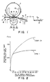
- Figure 1 is a sectional view of a preferred embodiment of the image heating apparatus in accordance with the present invention, which is a fixing apparatus for fixing thermally an unfixed image composed of toner particles.
- a reference numeral 10 designates an internal film guiding member shaped like a trough, the cross- sectional configuration of which is substantially half a circle.
- a groove in which a heater is to be fitted is cut in this guiding member 10, substantially in the middle of the outward racing bottom surface, along the longitudinal direction of the guiding member. The heater is supported by being fitted in this groove.
- a cylindrical fixing film 1 is loosely fitted around the internal film guiding member 10 fitted with the heater 6.
- a pressure roller 2 is pressed on the heater 6, with the film 1 being interposed between them. As the pressure roller 2 is rotatively driven, the cylindrical fixing film 1 rotates around the internal film guiding member 10, sliding on the bottom surface of the heater 6 while being tightly in contact with the surface.
- a recording material P is introduced between the film 1 and pressure roller 2 and enters a fixing nip N.
- the thermal energy of the heater 6 is given to the recording material P through the film 1, whereby the toner image is thermally fixed.
- tension is imparted on the film only in the portion in the fixing nip N and the portion in contact with the outward facing portion of the internal film guiding member 10, on the upstream side of the fixing nip with reference to the fixing nip N, and is not imparted on the rest of the film, which is the major portion of the film.
- the film shifting force is small, allowing a film shift movement regulating means and a film shift controlling means to be simplified.
- a simple component such as a flange may be employed as the film shift movement regulating means to hold the film edge, and the film shift controlling means may be omitted, making it possible to reducing the apparatus cost and downsizing the apparatus.
- a side of sheet is aligned with the sheet alignment reference at one lateral side regardless of the sheet size.
- a cylindrical polyimide film measuring 226 mm long, 24 mm wide, and 45 /1.m thick, the outward facing surface of which is coated 10 ⁇ m thick with PTFE.
- a pattern of silver/palladium is screen-printed as an exothermic layer on an aluminum substrate 3 (heater substrate) measuring 6.5 mm wide, 236 long, and 0.635 mm thick, and then, is baked to create an exothermic resistor having a resistance value of 28.3 Q.
- the thermistor 4 it is positioned on the heater substrate 3, on the back side (the surface opposite to the one where the exothermic layer 5 is present), 40 mm toward the sheet alignment reference from the longitudinal center of the substrate.
- a 4 mm thick silicone rubber roller layer 2b is fitted over a stainless steel shaft 2a having an external diameter of 8 mm.
- As the surface layer 2c fluorinated latex (GLS 213, a product of Daikin Industries, Ltd., containing FEP by 10 wt%) is coated 30 /1.m thick, and baked. The hardness is 50 degrees (Asker C).
- a thermal fixing apparatus comprising the above members is installed in an image forming apparatus such as a printer or electrophotographic copying machine.
- the sheet interval D is set at steady 50 mm, but when the sheets of the smaller size such as the B5 or envelope size are fed, the sheet interval D is gradually increased as the count of the consecutively fed sheets increases.
- One hundred B5 size sheets were consecutively fed, wherein the sheet interval D was controlled to be widened every 10 sheets as shown in Table 1.
- the temperature of the heater 6 was controlled to be 180°C.
- the temperature variation of the pressure roller 2 was measured at the non-sheet passage portion from the first sheet through the 100th sheet. The results are shown as a solid line in the graph of Figure 2.
- the temperature of the pressure roller 2 at the non-sheet passage portion remained below 130°C, and its difference from the temperature at the sheet passage portion, that is, 120°C, was small, causing no film damage nor wrinkling of the sheets.
- the sheet interval D was simply switched every predetermined number of sheets.
- the sheet interval D may end up being widened more than necessary, due to other parameters such as what kind of environment the apparatus is in, how warm the apparatus is immediately before the following sheet begins to be fed, or how long it takes for the apparatus to exchange the imaging data with the host computer, which may result in a reduced throughput.
- the power necessary for controlling the temperature of the heater 6 to be constant was detected, and the sheet interval D was controlled to be varied in response to this detected value of the power.
- a block diagram of this control system is shown in Figure 3.
- a CPU 15 takes in the output of the thermistor 4, through an A/D converter 16, and controls the power supply to the exothermic layer 5 of the heater 6, through an AC driver 17, whereby the temperature of the heater 6 is kept at a predetermined one.
- a power detection circuit 18 if it is of a type which controls the heater output based on the voltage of an AC input (AC power source) 19 and the wave number control, it measures the number of power supplying waves within a referential period, and computes the input power, the result of which is sent to the CPU.
- both the fixing film 1 and pressure roller 2 have not been warmed up at the initial stage, and also, the ambient air is cool; therefore, the necessary amount of the power is large.
- the power necessary to keep the predetermined temperature decreases.
- an AC power of 100 V and 50 Hz was used, and half a wave cycle was counted as a single wave unit, wherein ten cycles (20 wave units) were organized into a single control unit within which the number of wave units to be activated was varied. With such an arrangement in place, the number of wave units necessary to maintain the heater temperature at 155°C was measured from the first sheet which was fed at the start up, at the room temperature, through the 100th sheet.
- the predetermined temperature level is maintained by switching the number of wave units between an H level which is higher by a single wave unit than the minimum number of the wave units necessary to maintain the predetermined temperature, and an L level which is lower by a single wave unit than the minimum number of the wave units, wherein when the L level lasts longer than one second, the minimum number of the wave units is reduced by a single wave unit.
- the arrangement allows the power to be switched to reflect various conditions by which the fixing apparatus is affected, for example, the temperature of the pressure roller.
- the basis on which the number of wave units was switched was employed as the basis on which the length of the sheet interval D was switched.
- this embodiment was more rational than the preceding Embodiment 1 in which the sheet interval D was increased solely on the basis of the number of sheets which had been fed, realizing a higher throughput and a safeguard against damages.
- Embodiment 1 when the feeding of the sheet was temporarily held after the 50th sheet, and then, was immediately restarted, the sheet counter was reset; therefore, there was a problem that the temperature increase in the non-sheet passage region became extreme.
- the control was executed to select the sheet interval D in consideration of this estimation; therefore, even when the feeding of the sheets was restarted immediately after the interruption, the temperature increase never became extreme. The comparison between these two cases is given in Figure 4.
- the heater temperature was controlled to be constant, but an additional control may be executed in combination to lower gradually the heater temperature.
- the heater 6 was turned off for a predetermined period during the sheet interval D, wherein the length of the sheet interval D was determined in response to the amount of the temperature decrease which occurred during this predetermined period.
- Figure 5(a) shows the temperature drop in a case in which after the fixing apparatus was started up at a room temperature, the heater was turned off for 0.3 second during the sheet interval D between the first and second sheets
- Figure 5(b) shows the temperature drop in a case in which the heater was turned off for 0.3 second during the sheet interval D between the 50th and 51 st sheets being consecutively fed.
- the sheet interval D was determined as shown in Table 3, based on the amount of temperature drop T which occurred during 0.3 second.
- the off-period of the heater was fixed, but instead, the time it takes for the temperature to drop a predetermined temperature range, for example, 150°C to 140°C, may be measured. In short, what is necessary is to measure the rate of the temperature drop.
- the rate of the temperature increase may be measured while the heater temperature is increased after the off-period, and when the rate increases, it is determined that the temperature of the apparatus is higher, whereby the control is executed to widen the sheet interval D.
- the heater is turned off during the sheet interval D, but instead, the amount of heat may be increased for a predetermined period, and then, the amount of the temperature increase which occurs during this predetermined period may be measured to determine how warm the fixing apparatus is, based on which the control is executed to widen the sheet interval D.
- Embodiment 3 was described with reference to a fixed control temperature, but if an additional control is executed in combination in which the control temperature is lowered in response to how warm the fixing apparatus is, the amount by which the sheet interval D is widened can be reduced. This is convenient for the user, and in addition, is preferable from the standpoint of safety and durability of the apparatus.
- Table 4 offers a comparison between Embodiment 3 and this embodiment of the sheet interval D which was required to reduce below 130°C the temperature of the pressure roller 2, at the non-sheet passage portion.
- the throughput can be increased further than the preceding embodiment.
- the heater was turned off for a predetermined period during the sheet interval D, but this off-period may be gradually prolonged as the fixing apparatus becomes warmer.
- This arrangement decreases the amount of heat supplied to the non-sheet passage portions of the pressure roller 2 and fixing film 1 during the sheet interval D, which in turn decreases the amount of the temperature increase in the non-sheet passage portions; therefore, the amount by which the sheet interval D is increased can be reduced compared to the preceding embodiment.
- the throughput can be maintained higher than the preceding embodiment, which is convenient for the user.
- the heater temperature may be controlled to be kept at 155°C only while the sheet is in contact with the heating portion of the fixing apparatus, and at substantially 130°C during the sheet interval, and then, may be again increased to 155°C by the time when the following sheet enters the fixing nip N. This arrangement can also prevent the heater temperature from dropping excessively.
- an image forming apparatus comprising the same image heating apparatus as the one in Embodiment 1 shown in Figure 1 was used, wherein the letter size or A4 size sheets were fed with a sheet interval D of 50 mm, but when the small size sheets such as the B5 or envelop size sheets which were identified as the small size sheets, based on the sheet size signal, the number of the consecutively fed sheets were counted, and when the number reached a specific count predetermined for each sheet size, a control was executed to interrupt the printing operation.
- the sheet count was established for each sheet size as shown in Table 6, at which the continuous printing is interrupted.
- the target temperature of the heater 6 was set at 180°C.
- the results were such that the temperature of the pressure roller 2 at the non-sheet passage portion remained below 130°C, displaying a smaller temperature difference from the temperature at the sheet passage portion, that is, 100°C, and there was no damage to the film and no sheet wrinkle.
- the results of measuring the temperature of the pressure roller 2 the non-sheet passage portion were given as the solid line in the graph shown in Figure 6.
- One hundred B5 size sheets were consecutively fed with a fixed sheet interval D of 50 mm.
- the results were such that the temperature of the pressure roller 2 at the non-sheet passage portion exceeded 165 ° C after 100 sheets were fed, creating a temperature difference of more than 65 °C from the temperature at the sheet passage portion, that is, 100°C; therefore, the external diameter of the pressure roller 2 became different in the shaft direction, causing the fixing film 1 to shift to a side. As a result, the film edge was buckled or wrinkles appeared on the A4 sheet fed immediately afterward.
- the continuous printing operation is interrupted at a specific sheet count predetermined for each sheet size, to suppress the temperature increase of the pressure roller 2 at the non-sheet passage portion so that the damages to the fixing film and the wrinkling of the recording sheet can be prevented.
- the target temperature of the heater was fixed at 180°C, but it is possible to lower this target temperature as the fixing film 1, pressure roller 2, and the like component are gradually warmed up through the continuous printing operation.
- the sheet count at which the printing operation was interrupted was determined by beginning counting the number of the sheet fed after the target temperature was lowered to 155°C.
- the temperature increase at the non-sheet passage portion became smaller by approximately 20 degrees. Therefore, the problematic temperature increase became smaller compared to the preceding Embodiment 6, whereby the sheet count before the printing operation was stopped was increased, making the apparatus much easier for the user to operate.
- an off-period was provided for the heater during the sheet interval, and whether or not the printing operation was to be stopped was determined based on the temperature change after the off-period.
- Figure 8(a) shows the temperature drop in a case in which after the fixing apparatus was started up at a room temperature, the heater was turned off for 0.3 second during the sheet interval D between the first and second sheets
- Figure 8(b) shows the temperature drop in a case in which the heater was turned off for 0.3 second during the sheet interval D between the 50th and 51 st sheets being consecutively fed.
- a control may be executed to reduce the amount of the heat generated by the heater, instead of turning off the heater.
- an off-period was provided for the heater during the sheet interval in the same manner as in Embodiment 8, during which whether or not the printing operation was to be stopped was determined based on the rate at which the temperature dropped.
- the duration of the off-period for the heater was fixed, but instead, the time it takes for the temperature to drop a predetermined temperature range, for example, from 150 ° C to 140°C, may be measured. In short, all that is necessary is to measure the rate at which the temperature drops.
- the rate at which the temperature rises after the heater is reactivated after the off-period may be measured, and when the rate increases, it is determined that the temperature at the non-sheet passage portion has increased, and a control is executed to stop the printing operation.
- the heater was turned off during the sheet interval, but instead, the amount of the heat may be increased for a predetermined period, during which the amount of the temperature increase is measured to determine how high the temperature at the non-sheet passage portion is, and a control is executed to stop the printer, based on this measurement.
- the printing operation was stopped when it was determined that the temperature increase at the non-sheet passage portion became excessive while the small size sheets were consecutively fed. At this time, a display recognizable to the user can be presented, or a signal can be sent to the host computer or the like connected to the apparatus, which offers the benefit of informing the user of the apparatus status so that perplexing or confusing him it can be avoided.
- This embodiment relates to a method for releasing the apparatus from a print-lock status which might have occurred in Embodiments 6 - 10.
- the apparatus prefferably for the apparatus to be automatically released from the print-lock status as soon as the temperature at the non-sheet passage portion sufficiently drops after the printing operation is stopped.
- the temperature increase at the non-sheet passage portion could be indirectly measured by identifying the sheet size, counting the number of the consecutively fed sheets, or measuring the temperature variation when the heater was turned off during the sheet interval.
- the temperature drop at the non-sheet passage portion can be estimated from the temperature variation after the printing stoppage, the number of the prints before the time of the printing stoppage, or the elapsed time after the printing stoppage.
- Figure 10 shows an alternative embodiment of the image heating apparatus in accordance with the present invention, in which a roll of non-endless film is employed in place of the endless one.
- An image heating apparatus includes a heater which is stationary in use; a film slidable on the heater; a backup member cooperable the heater to form a nip, with the film being interposed between them, an image carried on a recording material being heated through the film in the nip by heat from the heater; and a feeding interval controlling device for varying the recording material interval with which the recording materials are consecutively fed.
Landscapes
- Physics & Mathematics (AREA)
- General Physics & Mathematics (AREA)
- Fixing For Electrophotography (AREA)
- Control Or Security For Electrophotography (AREA)
- Accessory Devices And Overall Control Thereof (AREA)
Applications Claiming Priority (2)
| Application Number | Priority Date | Filing Date | Title |
|---|---|---|---|
| JP4328837A JP2727899B2 (ja) | 1992-11-13 | 1992-11-13 | 像加熱装置及び画像形成装置 |
| JP328837/92 | 1992-11-13 |
Publications (2)
| Publication Number | Publication Date |
|---|---|
| EP0597496A1 true EP0597496A1 (de) | 1994-05-18 |
| EP0597496B1 EP0597496B1 (de) | 1998-04-01 |
Family
ID=18214643
Family Applications (1)
| Application Number | Title | Priority Date | Filing Date |
|---|---|---|---|
| EP93118386A Expired - Lifetime EP0597496B1 (de) | 1992-11-13 | 1993-11-12 | Bilderwärmungsapparat mit der Möglichkeit die Beschickungsintervalle zwischen den Aufzeichnungsmaterialien zu varieren |
Country Status (5)
| Country | Link |
|---|---|
| US (1) | US5669039A (de) |
| EP (1) | EP0597496B1 (de) |
| JP (1) | JP2727899B2 (de) |
| DE (1) | DE69317732T2 (de) |
| ES (1) | ES2113988T3 (de) |
Cited By (2)
| Publication number | Priority date | Publication date | Assignee | Title |
|---|---|---|---|---|
| EP0915394A3 (de) * | 1997-11-07 | 1999-12-15 | Canon Kabushiki Kaisha | Bildfixiergerät |
| EP1688804B1 (de) * | 2003-11-28 | 2013-10-09 | Fuji Xerox Co., Ltd | Bilderzeugungsverfahren |
Families Citing this family (31)
| Publication number | Priority date | Publication date | Assignee | Title |
|---|---|---|---|---|
| JPH09297433A (ja) * | 1996-05-08 | 1997-11-18 | Minolta Co Ltd | ディジタル複写機 |
| JP3389475B2 (ja) * | 1997-09-19 | 2003-03-24 | シャープ株式会社 | 画像形成装置 |
| US6185389B1 (en) | 2000-01-28 | 2001-02-06 | Lexmark International, Inc. | Control of thermal heating in a belt fuser |
| US6253046B1 (en) | 2000-04-19 | 2001-06-26 | Lexmark International, Inc. | Multi-functional fuser backup roll release mechanism |
| US6285838B1 (en) | 2000-09-01 | 2001-09-04 | Lexmark International, Inc. | Belt fuser overheat control |
| JP4659204B2 (ja) | 2000-11-24 | 2011-03-30 | キヤノン株式会社 | 定着装置及びこの定着装置を備える画像形成装置 |
| JP4125023B2 (ja) | 2001-03-13 | 2008-07-23 | キヤノン株式会社 | 定着装置 |
| JP5054868B2 (ja) * | 2001-07-03 | 2012-10-24 | キヤノン株式会社 | 画像形成装置 |
| JP2003255769A (ja) * | 2002-02-28 | 2003-09-10 | Ricoh Co Ltd | 画像形成装置 |
| JP2004205988A (ja) | 2002-12-26 | 2004-07-22 | Canon Inc | 加熱装置 |
| EP1632822B1 (de) * | 2004-09-06 | 2017-04-05 | Canon Kabushiki Kaisha | Bilderzeugungsapparat und Bilderzeugungsverfahren |
| JP4829551B2 (ja) * | 2004-09-07 | 2011-12-07 | キヤノン株式会社 | 画像形成装置 |
| US7702249B2 (en) | 2004-09-07 | 2010-04-20 | Canon Kabushiki Kaisha | Image forming apparatus with variable temperature treating modes |
| JP4549199B2 (ja) | 2005-02-08 | 2010-09-22 | キヤノン株式会社 | 画像加熱装置 |
| JP2007025237A (ja) | 2005-07-15 | 2007-02-01 | Ricoh Co Ltd | 定着装置及び画像形成装置 |
| JP4794954B2 (ja) * | 2005-09-13 | 2011-10-19 | キヤノン株式会社 | 画像加熱装置 |
| JP5173464B2 (ja) | 2008-02-08 | 2013-04-03 | キヤノン株式会社 | 画像形成装置 |
| JP2009199030A (ja) * | 2008-02-25 | 2009-09-03 | Murata Mach Ltd | 画像形成装置 |
| US20100329766A1 (en) * | 2009-06-26 | 2010-12-30 | Daniel Paul Cahill | Device and method for printing banner media |
| US7957661B2 (en) * | 2009-06-30 | 2011-06-07 | Lexmark International, Inc. | Control of overheating in an image fixing assembly |
| JP5538866B2 (ja) * | 2009-12-22 | 2014-07-02 | キヤノン株式会社 | 画像形成装置 |
| JP2011133524A (ja) * | 2009-12-22 | 2011-07-07 | Canon Inc | 画像形成装置 |
| US9213280B2 (en) * | 2013-10-21 | 2015-12-15 | Canon Kabushiki Kaisha | Image-forming apparatus supplying power to heat generating member using phase control and/or wave number control |
| JP2015221721A (ja) | 2014-04-30 | 2015-12-10 | キヤノン株式会社 | シート搬送装置及び画像形成装置 |
| JP6855745B2 (ja) * | 2016-10-14 | 2021-04-07 | ブラザー工業株式会社 | 画像形成装置および制御方法 |
| JP6939028B2 (ja) | 2017-03-31 | 2021-09-22 | ブラザー工業株式会社 | 画像形成装置 |
| JP6737228B2 (ja) * | 2017-04-27 | 2020-08-05 | 京セラドキュメントソリューションズ株式会社 | 画像形成装置 |
| JP2021076658A (ja) * | 2019-11-06 | 2021-05-20 | ブラザー工業株式会社 | 画像形成装置 |
| JP7414485B2 (ja) * | 2019-11-19 | 2024-01-16 | キヤノン株式会社 | 画像形成装置 |
| JP7634420B2 (ja) * | 2021-05-11 | 2025-02-21 | 東芝テック株式会社 | 画像形成装置 |
| JP2024150277A (ja) | 2023-04-10 | 2024-10-23 | キヤノン株式会社 | 画像形成装置 |
Citations (12)
| Publication number | Priority date | Publication date | Assignee | Title |
|---|---|---|---|---|
| JPS5714866A (en) * | 1980-06-30 | 1982-01-26 | Fuji Xerox Co Ltd | Control device for copying machine |
| JPS6041050A (ja) * | 1983-08-16 | 1985-03-04 | Canon Inc | 像形成装置 |
| JPS6118983A (ja) | 1984-07-06 | 1986-01-27 | Toshiba Corp | 画像形成装置 |
| EP0362791A2 (de) * | 1988-10-03 | 1990-04-11 | Canon Kabushiki Kaisha | Bilderzeugungsgerät |
| EP0402143A2 (de) * | 1989-06-07 | 1990-12-12 | Canon Kabushiki Kaisha | Bilderzeugungsgerät |
| EP0415752A2 (de) * | 1989-09-01 | 1991-03-06 | Canon Kabushiki Kaisha | Bilderzeugungsgerät |
| US5148226A (en) | 1990-06-11 | 1992-09-15 | Canon Kabushiki Kaisha | Heating apparatus using endless film |
| US5149941A (en) | 1987-06-16 | 1992-09-22 | Canon Kabushiki Kaisha | Image fixing apparatus with movable sheet member and detectors |
| EP0534417A2 (de) | 1991-09-24 | 1993-03-31 | Canon Kabushiki Kaisha | Bildheizgerät mit mehreren Temperaturdetektoren |
| US5204723A (en) | 1990-11-02 | 1993-04-20 | Canon Kabushiki Kaisha | Heating apparatus having heater with branch |
| US5262834A (en) | 1988-12-06 | 1993-11-16 | Canon Kabushiki Kaisha | Image fixing apparatus |
| US5525775A (en) | 1990-06-11 | 1996-06-11 | Canon Kabushiki Kaisha | Heating apparatus using endless film |
Family Cites Families (19)
| Publication number | Priority date | Publication date | Assignee | Title |
|---|---|---|---|---|
| JPS5480135A (en) * | 1977-12-09 | 1979-06-26 | Fuji Xerox Co Ltd | Method of controlling temperature of fixing unit for copying machine |
| US4416534A (en) * | 1981-11-05 | 1983-11-22 | Xerox Corporation | Apparatus and method for registering copy sheets in a variable pitch reproduction machine |
| US4719489A (en) * | 1984-02-03 | 1988-01-12 | Canon Kabushiki Kaisha | Recording apparatus having material feed mode dependent fixing control |
| JPS60207155A (ja) * | 1984-03-30 | 1985-10-18 | Mita Ind Co Ltd | 複写機 |
| JPS62187364A (ja) * | 1986-02-14 | 1987-08-15 | Ricoh Co Ltd | 画像形成装置 |
| JPS638779A (ja) * | 1986-06-30 | 1988-01-14 | Canon Inc | 画像処理装置 |
| US5171145A (en) * | 1988-11-11 | 1992-12-15 | Canon Kabushiki Kaisha | Image fixing apparatus for heat fixing a toner image through a film |
| JP2941827B2 (ja) * | 1988-12-15 | 1999-08-30 | キヤノン株式会社 | 記録装置 |
| US5307133A (en) * | 1989-07-07 | 1994-04-26 | Canon Kabushiki Kaisha | Image fixing apparatus with means for preventing moisture dew on film |
| JPH03163464A (ja) * | 1989-11-21 | 1991-07-15 | Mita Ind Co Ltd | 画像形成装置 |
| JPH03192382A (ja) * | 1989-12-22 | 1991-08-22 | Fuji Xerox Co Ltd | 定着装置 |
| JP2833088B2 (ja) * | 1990-01-09 | 1998-12-09 | キヤノン株式会社 | 定着装置 |
| JPH03209492A (ja) * | 1990-01-12 | 1991-09-12 | Canon Inc | 定着装置 |
| US5177549A (en) * | 1990-05-15 | 1993-01-05 | Canon Kabushiki Kaisha | Image forming apparatus supplied with controllable bias voltage |
| JP2847927B2 (ja) * | 1990-08-03 | 1999-01-20 | キヤノン株式会社 | 画像転写装置 |
| JPH04174457A (ja) * | 1990-11-07 | 1992-06-22 | Sharp Corp | 電子写真装置 |
| US5130750A (en) * | 1990-12-21 | 1992-07-14 | Xerox Corporation | Cross-pitch scheduling of documents and copy sheets in a copy system |
| US5184185A (en) * | 1991-08-29 | 1993-02-02 | Xerox Corporation | Method for duplex printing scheduling system combining finisher interset skipped pitches with duplex sheet scheduling |
| JPH06314008A (ja) * | 1993-04-28 | 1994-11-08 | Canon Inc | 定着装置 |
-
1992
- 1992-11-13 JP JP4328837A patent/JP2727899B2/ja not_active Expired - Lifetime
-
1993
- 1993-11-12 EP EP93118386A patent/EP0597496B1/de not_active Expired - Lifetime
- 1993-11-12 ES ES93118386T patent/ES2113988T3/es not_active Expired - Lifetime
- 1993-11-12 DE DE69317732T patent/DE69317732T2/de not_active Expired - Lifetime
-
1996
- 1996-09-30 US US08/720,470 patent/US5669039A/en not_active Expired - Lifetime
Patent Citations (12)
| Publication number | Priority date | Publication date | Assignee | Title |
|---|---|---|---|---|
| JPS5714866A (en) * | 1980-06-30 | 1982-01-26 | Fuji Xerox Co Ltd | Control device for copying machine |
| JPS6041050A (ja) * | 1983-08-16 | 1985-03-04 | Canon Inc | 像形成装置 |
| JPS6118983A (ja) | 1984-07-06 | 1986-01-27 | Toshiba Corp | 画像形成装置 |
| US5149941A (en) | 1987-06-16 | 1992-09-22 | Canon Kabushiki Kaisha | Image fixing apparatus with movable sheet member and detectors |
| EP0362791A2 (de) * | 1988-10-03 | 1990-04-11 | Canon Kabushiki Kaisha | Bilderzeugungsgerät |
| US5262834A (en) | 1988-12-06 | 1993-11-16 | Canon Kabushiki Kaisha | Image fixing apparatus |
| EP0402143A2 (de) * | 1989-06-07 | 1990-12-12 | Canon Kabushiki Kaisha | Bilderzeugungsgerät |
| EP0415752A2 (de) * | 1989-09-01 | 1991-03-06 | Canon Kabushiki Kaisha | Bilderzeugungsgerät |
| US5148226A (en) | 1990-06-11 | 1992-09-15 | Canon Kabushiki Kaisha | Heating apparatus using endless film |
| US5525775A (en) | 1990-06-11 | 1996-06-11 | Canon Kabushiki Kaisha | Heating apparatus using endless film |
| US5204723A (en) | 1990-11-02 | 1993-04-20 | Canon Kabushiki Kaisha | Heating apparatus having heater with branch |
| EP0534417A2 (de) | 1991-09-24 | 1993-03-31 | Canon Kabushiki Kaisha | Bildheizgerät mit mehreren Temperaturdetektoren |
Non-Patent Citations (4)
| Title |
|---|
| BRANDON ET AL.: "Fusing Offset Masters", IBM TECHNICAL DISCLOSURE BULLETIN., vol. 23, no. 10, March 1981 (1981-03-01), NEW YORK US, pages 4432 * |
| PATENT ABSTRACTS OF JAPAN vol. 10, no. 165 (P - 467) 12 June 1986 (1986-06-12) * |
| PATENT ABSTRACTS OF JAPAN vol. 6, no. 79 (P - 115) 18 May 1982 (1982-05-18) * |
| PATENT ABSTRACTS OF JAPAN vol. 9, no. 163 (P - 371) 9 July 1985 (1985-07-09) * |
Cited By (3)
| Publication number | Priority date | Publication date | Assignee | Title |
|---|---|---|---|---|
| EP0915394A3 (de) * | 1997-11-07 | 1999-12-15 | Canon Kabushiki Kaisha | Bildfixiergerät |
| US6115563A (en) * | 1997-11-07 | 2000-09-05 | Canon Kabushiki Kaisha | Image fixing apparatus |
| EP1688804B1 (de) * | 2003-11-28 | 2013-10-09 | Fuji Xerox Co., Ltd | Bilderzeugungsverfahren |
Also Published As
| Publication number | Publication date |
|---|---|
| EP0597496B1 (de) | 1998-04-01 |
| JPH06149103A (ja) | 1994-05-27 |
| DE69317732D1 (de) | 1998-05-07 |
| HK1011757A1 (en) | 1999-07-16 |
| ES2113988T3 (es) | 1998-05-16 |
| DE69317732T2 (de) | 1998-09-24 |
| US5669039A (en) | 1997-09-16 |
| JP2727899B2 (ja) | 1998-03-18 |
Similar Documents
| Publication | Publication Date | Title |
|---|---|---|
| EP0597496A1 (de) | Bilderwärmungsapparat mit der Möglichkeit die Beschickungsintervalle zwischen den Aufzeichnungsmaterialien zu varieren | |
| JP3880424B2 (ja) | 画像形成装置 | |
| US5862435A (en) | Image forming apparatus | |
| JP4944987B2 (ja) | 画像形成方法 | |
| CN107924156B (zh) | 图像加热设备 | |
| EP0632345B1 (de) | Bilderzeugungsgerät | |
| JP5054868B2 (ja) | 画像形成装置 | |
| EP1703338A1 (de) | Bilderfixiervorrichtung mit einem Temperatursensor für ein induktiv erhitztes Fixierband | |
| US5436709A (en) | Fixing device which controls an energizing condition of a heater after fixing operation | |
| JP2776101B2 (ja) | 加熱装置 | |
| CN108475034A (zh) | 定影装置和成像装置 | |
| US20180246456A1 (en) | Image forming apparatus | |
| JP3844201B2 (ja) | 定着装置及びこれを有する画像形成装置 | |
| JP3848001B2 (ja) | 加熱定着装置および画像形成装置 | |
| JP3102136B2 (ja) | 加熱装置 | |
| HK1011757B (en) | Image heating apparatus capable of varying feeding intervals between recording materials | |
| JP2001183929A (ja) | 像加熱装置及び画像形成装置 | |
| JP3125569B2 (ja) | 像加熱装置 | |
| JP4642213B2 (ja) | 画像形成装置 | |
| JPH07248697A (ja) | 定着装置 | |
| JP2008275753A (ja) | 加熱定着装置 | |
| JP3958108B2 (ja) | 画像形成装置 | |
| JP2006038920A (ja) | 画像形成装置 | |
| JPH05150675A (ja) | 画像形成装置 | |
| JPH06202507A (ja) | 加熱装置 |
Legal Events
| Date | Code | Title | Description |
|---|---|---|---|
| PUAI | Public reference made under article 153(3) epc to a published international application that has entered the european phase |
Free format text: ORIGINAL CODE: 0009012 |
|
| 17P | Request for examination filed |
Effective date: 19931112 |
|
| AK | Designated contracting states |
Kind code of ref document: A1 Designated state(s): DE ES FR GB IT NL |
|
| 17Q | First examination report despatched |
Effective date: 19951205 |
|
| GRAG | Despatch of communication of intention to grant |
Free format text: ORIGINAL CODE: EPIDOS AGRA |
|
| GRAG | Despatch of communication of intention to grant |
Free format text: ORIGINAL CODE: EPIDOS AGRA |
|
| GRAH | Despatch of communication of intention to grant a patent |
Free format text: ORIGINAL CODE: EPIDOS IGRA |
|
| GRAH | Despatch of communication of intention to grant a patent |
Free format text: ORIGINAL CODE: EPIDOS IGRA |
|
| GRAA | (expected) grant |
Free format text: ORIGINAL CODE: 0009210 |
|
| AK | Designated contracting states |
Kind code of ref document: B1 Designated state(s): DE ES FR GB IT NL |
|
| REF | Corresponds to: |
Ref document number: 69317732 Country of ref document: DE Date of ref document: 19980507 |
|
| REG | Reference to a national code |
Ref country code: ES Ref legal event code: FG2A Ref document number: 2113988 Country of ref document: ES Kind code of ref document: T3 |
|
| ITF | It: translation for a ep patent filed | ||
| ET | Fr: translation filed | ||
| PLBE | No opposition filed within time limit |
Free format text: ORIGINAL CODE: 0009261 |
|
| STAA | Information on the status of an ep patent application or granted ep patent |
Free format text: STATUS: NO OPPOSITION FILED WITHIN TIME LIMIT |
|
| 26N | No opposition filed | ||
| REG | Reference to a national code |
Ref country code: GB Ref legal event code: IF02 |
|
| PGFP | Annual fee paid to national office [announced via postgrant information from national office to epo] |
Ref country code: DE Payment date: 20101130 Year of fee payment: 18 |
|
| PGFP | Annual fee paid to national office [announced via postgrant information from national office to epo] |
Ref country code: IT Payment date: 20101112 Year of fee payment: 18 Ref country code: GB Payment date: 20101126 Year of fee payment: 18 |
|
| PGFP | Annual fee paid to national office [announced via postgrant information from national office to epo] |
Ref country code: NL Payment date: 20111123 Year of fee payment: 19 Ref country code: FR Payment date: 20111212 Year of fee payment: 19 Ref country code: ES Payment date: 20111102 Year of fee payment: 19 |
|
| REG | Reference to a national code |
Ref country code: NL Ref legal event code: V1 Effective date: 20130601 |
|
| GBPC | Gb: european patent ceased through non-payment of renewal fee |
Effective date: 20121112 |
|
| REG | Reference to a national code |
Ref country code: FR Ref legal event code: ST Effective date: 20130731 |
|
| PG25 | Lapsed in a contracting state [announced via postgrant information from national office to epo] |
Ref country code: NL Free format text: LAPSE BECAUSE OF NON-PAYMENT OF DUE FEES Effective date: 20130601 Ref country code: IT Free format text: LAPSE BECAUSE OF NON-PAYMENT OF DUE FEES Effective date: 20121112 |
|
| REG | Reference to a national code |
Ref country code: DE Ref legal event code: R119 Ref document number: 69317732 Country of ref document: DE Effective date: 20130601 |
|
| PG25 | Lapsed in a contracting state [announced via postgrant information from national office to epo] |
Ref country code: DE Free format text: LAPSE BECAUSE OF NON-PAYMENT OF DUE FEES Effective date: 20130601 |
|
| PG25 | Lapsed in a contracting state [announced via postgrant information from national office to epo] |
Ref country code: GB Free format text: LAPSE BECAUSE OF NON-PAYMENT OF DUE FEES Effective date: 20121112 Ref country code: FR Free format text: LAPSE BECAUSE OF NON-PAYMENT OF DUE FEES Effective date: 20121130 |
|
| REG | Reference to a national code |
Ref country code: ES Ref legal event code: FD2A Effective date: 20140304 |
|
| PG25 | Lapsed in a contracting state [announced via postgrant information from national office to epo] |
Ref country code: ES Free format text: LAPSE BECAUSE OF NON-PAYMENT OF DUE FEES Effective date: 20121113 |