EP0601364A1 - Filmbildbearbeitungsgerät - Google Patents
Filmbildbearbeitungsgerät Download PDFInfo
- Publication number
- EP0601364A1 EP0601364A1 EP93118678A EP93118678A EP0601364A1 EP 0601364 A1 EP0601364 A1 EP 0601364A1 EP 93118678 A EP93118678 A EP 93118678A EP 93118678 A EP93118678 A EP 93118678A EP 0601364 A1 EP0601364 A1 EP 0601364A1
- Authority
- EP
- European Patent Office
- Prior art keywords
- image
- size
- density variation
- editing
- picture size
- Prior art date
- Legal status (The legal status is an assumption and is not a legal conclusion. Google has not performed a legal analysis and makes no representation as to the accuracy of the status listed.)
- Withdrawn
Links
Images


Classifications
-
- G—PHYSICS
- G03—PHOTOGRAPHY; CINEMATOGRAPHY; ANALOGOUS TECHNIQUES USING WAVES OTHER THAN OPTICAL WAVES; ELECTROGRAPHY; HOLOGRAPHY
- G03B—APPARATUS OR ARRANGEMENTS FOR TAKING PHOTOGRAPHS OR FOR PROJECTING OR VIEWING THEM; APPARATUS OR ARRANGEMENTS EMPLOYING ANALOGOUS TECHNIQUES USING WAVES OTHER THAN OPTICAL WAVES; ACCESSORIES THEREFOR
- G03B27/00—Photographic printing apparatus
- G03B27/32—Projection printing apparatus, e.g. enlarger, copying camera
- G03B27/46—Projection printing apparatus, e.g. enlarger, copying camera for automatic sequential copying of different originals, e.g. enlargers, roll film printers
- G03B27/462—Projection printing apparatus, e.g. enlarger, copying camera for automatic sequential copying of different originals, e.g. enlargers, roll film printers in enlargers, e.g. roll film printers
-
- H—ELECTRICITY
- H04—ELECTRIC COMMUNICATION TECHNIQUE
- H04N—PICTORIAL COMMUNICATION, e.g. TELEVISION
- H04N1/00—Scanning, transmission or reproduction of documents or the like, e.g. facsimile transmission; Details thereof
- H04N1/387—Composing, repositioning or otherwise geometrically modifying originals
-
- G—PHYSICS
- G03—PHOTOGRAPHY; CINEMATOGRAPHY; ANALOGOUS TECHNIQUES USING WAVES OTHER THAN OPTICAL WAVES; ELECTROGRAPHY; HOLOGRAPHY
- G03B—APPARATUS OR ARRANGEMENTS FOR TAKING PHOTOGRAPHS OR FOR PROJECTING OR VIEWING THEM; APPARATUS OR ARRANGEMENTS EMPLOYING ANALOGOUS TECHNIQUES USING WAVES OTHER THAN OPTICAL WAVES; ACCESSORIES THEREFOR
- G03B2227/00—Photographic printing apparatus
- G03B2227/005—Matrix print; Index print
Definitions
- the present invention relates to a film image editing apparatus that reads from a developed photographic film a plurality of images photographed on the photographic film.
- images (documents) are inputted from an input drum and then edited images are outputted, which means that the apparatus is not on the assumption that images photographed on a photographic film are read from the photographic film processed.
- images photographed on a photographic film are usually in various sizes of plural kinds including normal picture size (full size), a panorama size which oblong being long from side to side and a half size. Therefore, it has been difficult to apply the apparatus.
- the same 35 mm film has therein various picture sizes such as a full size, an oblong size (a panorama size and a low-aspect-ratio size), and a half size.
- various picture sizes such as a full size, an oblong size (a panorama size and a low-aspect-ratio size), and a half size.
- normal photographing full size photographing
- panorama size photographing can be switched in the course of photographing on a single roll of film, thus a film having therein different picture sizes has made its appearance.
- the editing apparatus as disclosed in the Japanese Patent Examined Publication mentioned above is one wherein a display indicates only images after editing. In the case of editing, therefore, it is not possible to observe inputted images which were actually read. Accordingly, it is necessary to put inputted images in order and to decide an layout before conducting a work which requires skillfulness and is specialized. With the background mentioned above, easy editing work has been desired.
- Japanese Patent Publication Open to Public Inspection No. 272755/1987 discloses one wherein color correction by means of cursor input or the like on a color chart is made for each picture area and a point is designated on each picture area so that color before correction and color after correction on the designated point may be indicated for judging whether the correction has been made appropriately or not.
- an object of the invention is to provide a film image editing apparatus which can read correctly images photographed on a photographic film and edit them even in the case where each photographic film has a different picture size or the same photographic film has different picture sizes.
- Further object of the invention is to make editing work easy by enabling an operator to edit while observing actually plural images which have been read from a developed photographic film and are on standby for editing, and further to make image correction (especially, color correction) and layout editing easy.
- the film image editing apparatus of the invention comprises image information reading means (A) that reads image information on each picture area having an ordinary picture size from a developed photographic film as shown in Fig. 1, picture size detecting means (B) that detects a picture size of each image from density variation information on each picture area to be read based on image information read by the image information reading means, editing means (C) that edits, according to input from the outside for instructing the edition, a plurality of images decided by both image information read by the image information reading means and picture sizes detected by the picture size detecting means, and output means (D) that outputs images edited by the editing means.
- image information reading means A
- picture size detecting means B
- editing means that edits, according to input from the outside for instructing the edition, a plurality of images decided by both image information read by the image information reading means and picture sizes detected by the picture size detecting means
- output means (D) that outputs images edited by the editing means.
- the image information reading means (A) is preferably one wherein the photographic film and the line sensor both mentioned above are moved relatively in the secondary scanning direction while the line sensor is scanning a developed photographic film in the primary scanning direction, and thereby image information on the photographic film is read by the line sensor.
- the picture size detecting means (B) mentioned above comprises a density variation detecting means that detects the pattern of density variation in the predetermined direction on each picture area to be read based on image information read by the image information reading means and a picture size judging means that judges picture size of each image by comparing the pattern of density variation detected by the density variation detecting means with a reference pattern.
- the density variation detecting means is one wherein the pattern of density variation in the longitudinal direction on each of non-image recording areas formed to have a predetermined width over and below the oblong size picture area on a full size frame can be detected.
- the density variation detecting means may be one wherein the pattern of density variation in the longitudinal direction on an area formed to have a predetermined width between two half size picture areas on a full size frame can be detected.
- the density variation detecting means is preferably one wherein a binary coding means that binary-codes image information read by the image information reading means is provided, and the pattern of density variation is detected based on data binary-coded by the binary-coding means.
- the editing means (C) is provided with a display means capable of index-displaying plural images decided by both image information read by the image information reading means and picture sizes detected by the picture size detecting means.
- the editing means (C) is provided with a correction image selecting means that selects the image to be corrected from a plurality of images decided by both image information read by the image information reading means and picture sizes detected by the picture size detecting means, and with a correcting means that corrects the selected image according to input for instructing the correction.
- the correcting means in this case may preferably be provided with a color correction area designating means that designates an area where color correction is made on an original image, a target color selecting means that selects a target color from plural target colors established in advance as a target color for color correction, and a color converting means that performs color conversion for images so that the designated area may match the selected target color.
- the editing means (C) mentioned above may further be provided with an edition image selecting means that selects images to be edited from plural images decided by both image information read by the image information reading means and picture sizes detected by the picture size detecting means and with a layout editing means that edits the selected images according to the predetermined layout.
- image information on each picture area having a normal picture size is first read from a developed photographic film by the image information reading means (A).
- the developed photographic film is scanned in the primary scanning direction and in the secondary scanning direction by a line sensor, thus image information recorded on a photographic film is read on a two-dimensional basis.
- a picture size of each image is detected by the picture size detecting means (B) from density variation information on each picture area to be read based on image information read by the aforementioned image information reading means.
- the pattern of density variation in the predetermined direction on each picture area to be read is detected based on image information read. Then, the pattern of density variation detected is compared with a reference pattern corresponding to specific pattern of density variation on each picture size, and a picture size of each image is judged based on the results of the aforesaid comparison.
- detection of the pattern of density variation may be made in the longitudinal direction of an area with a predetermined width formed as a non-image recording area outside an oblong size (panorama size, low-aspect-ratio size) area or a half size area on a full size frame.
- a full size, an oblong size and a half size may be judged by whether or not the pattern of density variation on the area mentioned above corresponds to the non-image recording area for an oblong size or a half size.
- image information read may be binary-coded based on a reference level capable of distinguishing between an image recording area and a non-image recording area, and the pattern of density variation may be detected based on the binary-coded data.
- Fig. 1 is a block diagram in terms of function showing the constitution of the invention.
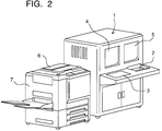
- Fig. 2 is a sketch drawing of a film image editing apparatus showing an example of the invention.
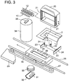
- Fig. 3 is a structural diagram of a film reading device.
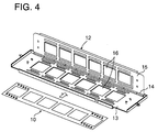
- Fig. 4 is a perspective view of a film holder.
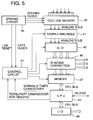
- Fig. 5 is a block diagram showing the circuit structure of a film reading device.
- Fig. 6 is a time chart showing a normal mode and an 8 times greater speed mode.
- Fig. 7 is a diagram showing how different picture sizes are mixed in a photographic film.
- Fig. 8 is a diagram showing detecting areas (judgment areas) for density variation.
- Fig. 9 is a diagram showing a pattern of density variation caused by picture sizes.
- Fig. 10 is a diagram showing a pattern of density variation caused by picture sizes.
- Fig. 11 is a time chart showing a full image reading mode.
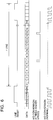
- Fig. 12 is a time chart showing a partial image reading mode.
- Fig. 13 is a time chart showing the total flow of picture size detection.
- Fig. 14 is a flow chart showing the detailed contents of picture size detection.
- Fig. 15 is a diagram showing a pattern of density variation in a panorama size.
- Fig. 16 is a diagram showing a pattern of density variation in a half size.
- Fig. 17 is a diagram showing a pattern of density variation in a full size.
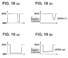
- Fig. 18 is a diagram showing a pattern of density variation in the case of occurrence of noise in a panorama size.
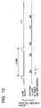
- Fig. 19 is a diagram showing a pattern of density variation in the primary scanning direction in the case of a panorama size.
- Fig. 20 is a flow chart showing the total flow of an editing work.
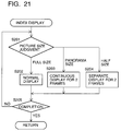
- Fig. 21 is a flow chart of index-display.
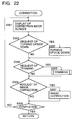
- Fig. 22 is a flow chart of a correction mode.
- Fig. 23 is a flow chart of an image correction mode.
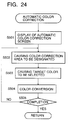
- Fig. 24 is a flow chart of an automatic color correction mode.
- Fig. 25 is a diagram showing display example 1 for a touch panel and CRT.
- Fig. 26 is a diagram showing display example 2 for a touch panel and CRT.
- Fig. 27 is a diagram showing display example 3 for a touch panel and CRT.
- Fig. 28 is a diagram showing display example 4 for a touch panel and CRT.
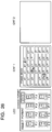
- Fig. 29 is a diagram showing display example 5 for a touch panel and CRT.
- Fig. 30 is a diagram showing display example 6 for a touch panel and CRT.
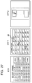
- Fig. 31 is a diagram showing display example 7 for a touch panel and CRT.
- Fig. 2 is a sketch drawing of a film image editing apparatus.
- cassette inlet 2 for film reading and touch panel (LCD) 3 of a liquid crystal type for operation there are provided first CRT 4 for indicating input images and second CRT 5 for indicating output images on a side by side basis.
- Printer 7 provided with scanner 6 for reading reflection type originals can be connected to the image editing apparatus main body 1.
- Fig. 3 is a structural drawing of a film reading unit portion.
- developed photographic films (negative films) 10 each having 6 frames are held by film holder 12, and film holders 12 in the maximum quantity of 7 are housed in cassette 20.
- the cassette 20 is inserted into the cassette inlet 2.
- the film holder 12 is provided with lower frame 13 and upper frame 15 affixed through shaft 14 in the hinge type as shown in Fig. 4, and photographic film 10 is sandwiched between the lower frame 13 and the upper frame 15 to be held.
- Cassette 20 is a case whose front side is open and 7 steps of holding grooves 21 are formed on each of both sides of the cassette, and film holders 12 in quantity of the maximum 7 can be held in the cassette with their both ends guided by holding grooves 21 at both sides of the cassette in the state that film surfaces are in parallel with each other. Each film holder in the cassette can be drawn out in the direction of the film surface.
- film holders 12 for negative films are housed in cassette 20, and 6 frames x 7 holders, the maximum 42 frames in total can be housed in the cassette.
- the maximum 35 frames in total can be housed.
- Film holders for a negative film and those for a positive film can naturally be housed mixedly.
- film holder transport devices 23 and 23 are provided on both sides of the cassette receiver 22.
- the film holder transport devices 23 are moved up or down by an elevating mechanism to the position where the film holder 12 to be transported is housed so that holding arms 24 thereon may hold the film holder 12, and then, the film holder transport devices are further moved back or forth by a sliding mechanism so that the film holder held by the holding arms 24 may be transported onto secondary scanning table 25.
- the secondary scanning table 25 is one on which film holder 12 transported by film holder transport devices 23 is placed, and it is provided with aperture 26 which faces a frame on a film.
- the secondary scanning table 25 is reciprocated by belt 30 driven by a stepping motor that is housed in driving unit 29 while being guided by two guide rails 27 and 28 extending in the direction perpendicular to the transporting direction of the film holder transport devices 23.
- lamp 31 converging mirror 32 and condenser lens 33 so that light emitted from the lamp 31 may be converged by the converging mirror 32 and condenser lens 33 to illuminate photographic film 10 held by the film holder 12.
- CCD line sensor 35 for color use through reading lens system (including a diaphragm and a filter) 34.
- the CCD line sensor 35 is one wherein a large number of pixels (photoelectric conversion elements) are arranged in the direction (primary scanning direction) perpendicular to the reciprocating direction (secondary scanning direction) of the secondary scanning table 25.
- cassette 20 wherein film holder 12 is housed is set on cassette inlet 2, designated film holder 12 is transported by transport device 23 onto secondary scanning table 25 from the cassette 20.
- the secondary scanning table 25 is moved by driving unit 29 so that signals of the CCD line sensor 35 may be read while the film holder 12 is moving, thus image information on all frames in the film holder 12 or image information of the designated frame can be obtained.
- an unillustrated origin mark is provided on the secondary scanning table 25, and when the origin mark is detected by an affixed unillustrated photosensor, the original position can be detected.
- an amount of driving an amount of rotation of a stepping motor
- each frame namely each picture area having an ordinary picture size (full size) can be read in succession.
- the driving unit 29 moves reversely the secondary scanning table 25 to return it to its initial position. Thereby, the film holder 12 on the secondary scanning table 25 is returned again to its original portion on the cassette 20 by the transport device 23.
- Rough scanning means reading images of all frames in the high speed (for example, 8 times greater speed) mode, namely reading roughly by reducing the number of pixels to be read, for the purpose of picture size detecting and index-displaying.
- 8 times greater speed for example, the number of pixels to be read is reduced to 1/8 in the primary scanning direction and secondary scanning direction respectively (totaling 1/64).
- images of all frames on all film holders 12 are read roughly at 8 times greater speed while a plurality of film holders 12 in the cassette 20 are transported onto the secondary scanning table 25.
- each film holder 12 is scanned twice, and the first scanning is called pre-scanning and the second one is called index-scanning.
- image data are obtained through the pre-scanning at 8 times greater speed, and then, reading conditions wherein gradation balance or the like is corrected based on the image data are established.
- image data are obtained while images are corrected based on the established reading conditions mentioned above.
- the film holder 12 containing the selected frame is transported from the cassette 20 onto the secondary scanning table 25, and images of the selected frame are read at the normal speed from the film holder 12. Even in this case of reading, correction is made with reading conditions established based on the data obtained in the pre-scanning mentioned above.
- Fig. 5 is a block diagram showing the circuit arrangement for a film reading unit.
- Analog image signals for each of the three primary colors (R, G and B) outputted from the CCD line sensor 35 for color use mentioned above are inputted in A/D converter 42 through sample-and-hold circuit 41, and the analog image signals are converted to digital image signals of each of three primary colors in the A/D converter 42.
- CPU 43 is connected to an actuator or a sensor in the mechanism portion shown in Fig. 3, and it has a function of controlling reading operation of the mechanism portion and a function to instruct to control circuit 44 either a normal mode for reading image data of all pixels or an 8 times greater speed mode reducing the number of pixels to be read to 1/8 in both the primary scanning direction and the secondary scanning direction, as a data reading mode.
- the control circuit 44 receives the signal for switching between normal/8 times higher modes, and controls sample-and-hold circuit 41 and A/D converter 42 in the normal mode or 8 times greater speed mode synchronizing with data clocks and line reset signals in driving circuit 45 that drives CCD line sensor 35 based on reference clock signals from an unillustrated oscillator, thus, it switches between fine scanning and rough scanning.
- A/D conversion is made at the timing shown in Fig. 6.
- Digital image signals outputted from the A/D converter 42 are subjected to shading correction made by shading correction circuit 46.
- first scanning pre-scanning
- second scanning index-scanning
- correction is made according to conditions for correction established based on the aforementioned scanning, to be stored in a frame memory in the later stage.
- photographic film 10 to be read is one wherein a panorama size picture area photographed with upper and lower shielded portions on a normal full size picture area and a half size picture area obtained by dividing a normal full size picture area into two equal parts are existing mixedly with a full size picture area.
- image processing for editing which is conducted based on image signals obtained by reading the photographic film 10
- picture sizes on the film need to be distinguished.
- digital image signals obtained through A/D conversion made by A/D converter 42 are stored temporarily in memory 47, and picture sizes are distinguished automatically based on the stored data.
- CPU 43 has a function to control, through control circuit 44, the operation of writing digital image signals to memory 47. Based on the digital image signals stored in the memory 47, picture sizes are distinguished in the manner mentioned later, and the results of the distinguishment are outputted to an image processing circuit for editing through I/O interface 48.
- Photographic film 10 to be read is one wherein a full size picture area, a panorama size picture area and a half size picture area are existing mixedly as shown in Fig. 7.
- a panorama size (or low-aspect-ratio size) which is oblong compared with a full size is formed by narrowing the full size picture area vertically with upper and lower non-image recording portions (light-shielded portions) each having a predetermined width.
- a half size is formed by dividing a full size picture area into two equal image-recording areas with a non-image recording portion having a predetermined width extending vertically (transverse direction of the film) on the central portion of the full size picture area.
- non-image recording portions within a full size picture area can be distinguished based on image signals which have been read as a full size picture area, it is possible to distinguish a full size, a panorama size and a half size.
- a non-image recording portion between two half size picture areas on a full size picture area is assumed as judgment area u ⁇ (see Fig. 8), and density variation in the longitudinal direction (primary scanning direction in the present example and is in accord with the transverse direction of the film) on the judgment area u ⁇ is detected.
- each of starting side and ending side shows the maximum transmissivity (minimum density) corresponding to each non-image recording portion having a predetermined width, and an in-between portion show relatively high density corresponding to image recording (see Fig. 10 (a)).
- the picture size is a half size, on the other hand, the judgment area u ⁇ mentioned above agrees with a non-image recording portion. Therefore, base density (minimum density) showing the maximum transmissivity is fixed (see Fig. 10 (b)).
- the portion from the starting point to the ending point is an image recording area. Therefore, density is kept to be higher than the minimum density (see Fig. 10 (c)).
- a non-image recording portion formed by a panorama size or by a half size on a full size picture area is specified as a judgment area, and the pattern of density variation in the longitudinal direction on the judgment area is detected.
- picture sizes (a full size, a panorama size and a half size) can be detected based on image signals read as a full size picture area, by judging agreement between the detected pattern and the pattern specific to each picture area (reference pattern)
- CPU 43 detects picture sizes based on digital image signals stored in memory 47.
- the digital image signals stored in the memory 47 are made to be rough scanning data for 8 times greater speed because they are the data used only for detection of picture sizes.
- the memory 47 may also be arranged so that image signals on the entire portion on a full size picture area may be stored in the memory 47.
- CPU 43 is arranged to be capable of giving instruction to control circuit 44 either for storing all areas in the memory 47 (full reading mode) or for storing only image signals of the aforementioned judgment area in the memory 47 (partial reading mode). Therefore, the control circuit 44 can output writing clocks shown in Fig. 11 or Fig. 12 to the memory 47 according to the instruction concerning storage area from the CPU 43.
- a flow chart in Fig. 13 shows a total flow of detection of picture sizes.
- step 1 (shown as S1 in the figure; which applies also to the following cases), the control circuit 44 is set to a mode of 8 times greater speed.
- step 2 discrimination is made for whether a full image reading mode is selected or a partial reading mode is selected. Depending on the results of the discrimination, the sequence advances to Step 3 or to step 4 to set the control circuit 44 to the full image reading mode or the partial reading mode so that image signals of a full image or image signals of only a judgment area may be stored in the memory 47.
- step 5 actual writing of digital image signals on the memory 47 is started and is kept until the moment when completion of the writing is confirmed in Step 6.
- a pattern of density variation in the predetermined direction on a picture area is detected in step 7 based on the data stored in the memory 47, and the pattern of density variation thus detected is compared with a reference pattern that is specific to each picture size, thus, a picture size can be detected.
- step 8 the detected picture size is outputted to an image processing circuit for editing use in the later step to be stored therein.
- a flow chart shown in Fig. 14 indicates in detail how a picture size is detected in step 7 in the flow chart shown in Fig. 13.
- step 11 image signals in each of judgment areas t1, t2 and u ⁇ (see Fig. 8) are averaged in its transverse direction so that a pattern of density variation in the longitudinal direction on each judgment area may be detected based on the mean value obtained through averaging.
- averaging may also be made in the direction for obtaining a pattern of density variation, in addition to the transverse direction.
- step 12 digital image signals subjected to the averaging processing mentioned above are binary-coded.
- a threshold level in the aforementioned binary-coding is established to the intermediate value between base density of photographic film 1 (density corresponding to non-image recording area) and the maximum density on an image recording area, and is binary-coded to the density level corresponding to a non-image recording area (light-shielded area) and to the density level corresponding to the maximum density on an image recording area (see Figs. 15 - 19).
- the threshold level mentioned above may also be variably established based on the result of detection of base density (transmissivity of a base portion) of each photographic film.
- step 13 discrimination is made for whether or not a pattern of density variation (pattern for indicating density variation with a binary number) in the secondary scanning direction detected on each of judgment areas t1 and t2 which are formed, as a non-image recording area (light-shielded area), respectively at the upper side and the lower side transversely on a full size picture area in the case of a panorama size agrees with a reference pattern of a panorama size representing the constant maximum transmissivity (corresponding to a base portion) as shown in Fig. 15 (a).
- a pattern of density variation pattern for indicating density variation with a binary number
- both two judgment areas t1 and t2 located respectively at the upper side and the lower side transversely on a film are light-shielded areas where no image is recorded. Therefore, each of them should show the density variation specific to a panorama size representing a constant maximum transmissivity as shown in Fig. 15 (a). In this case, the sequence advances to Step 14 and the read image is recognized to be of a panorama size.
- step 15 for distinguishing between a full size and a half size, discrimination is made for whether or not the pattern of density variation detected on each of judgment areas t1 and t2 formed respectively at the upper side and the lower side as a non-image recording area agrees with the pattern that the central portion of a picture area only shows a non-image recording area (reference pattern for a half size).
- the sequence advances to step 16 for recognizing that the picture size is a half size, while when it does not agree with the reference pattern, the sequence advances to step 17 for discriminating further whether or not the picture size is a full size remaining unchecked.
- step 17 discrimination is made for whether or not the pattern of density variation detected on each of judgment areas t1 and t2 agrees with the pattern shown in Fig. 17 (a) corresponding to the occasion where images are recorded (reference pattern of a full size).
- the sequence advances to step 18 for recognizing that the picture size is a full size.
- step 19 when the pattern of density variation on the lower judgment area t1 represents a pattern wherein the pattern showing that the most area is a non-image recording area and only a part thereof is an image recording area as shown in Fig. 18 (a) appears although the density variation in the secondary scanning direction (longitudinal direction in a judgment area) for the upper judgment area t2 agrees with the pattern (Fig. 15 (a)) of a panorama size, a portion representing the aforementioned image recording is estimated to be a noise caused by printing of a date or the like, and the sequence advances to step 20 for further confirmation.
- step 20 a pattern of density variation in the longitudinal direction (that agrees with the primary scanning direction) on judgment area u ⁇ which is a non-image recording area extended vertically at the center of a picture area in the case of a half size is detected, and then discrimination is made whether or not the detected pattern agrees with a reference pattern of a panorama size with which upper and lower non-image recording areas shown in Fig. 19 (a) are formed.
- steps 19 and 20 when the picture size is confirmed not to be a panorama size even when printing of a date is taken into consideration, the sequence advances to step 21 for processing under the condition of unknown picture size.
- the picture size is unknown, it is also possible to process under the condition that all picture sizes are a full size.
- a portion of step 14 in Fig. 14 corresponds to a means for detecting density variation
- a portion of step 12 corresponds to a means for binary-coding
- a portion of steps 13 - 21 corresponds to a means for judging picture sizes.
- judgment areas t1, t2 and judgment area u ⁇ In detection of picture sizes shown in a flow chart in Fig. 14, there are used judgment areas t1, t2 and judgment area u ⁇ , however, either judgment areas t1 and t2 or judgment area u ⁇ only may also be used as a judgment area.
- a flow of an editing work in the present film image editing apparatus will be explained as follows, referring to the flow charts in Figs. 20 - 24 and display examples in Figs. 25 - 31.
- the section of "LCD” shows an image area of touch-panel 3 of a liquid crystal type
- the section of "CRT1” shows an image area of first CRT4
- the section of "CRT2” shows an image area of second CRT5.
- Fig. 20 is a flow chart showing the total flow of an editing work.
- the image area of the touch panel instructs to insert a cassette, and a start button operated after the insertion of the cassette starts the apparatus to read from the cassette (step 101 in Fig. 20).
- a plurality of film holders 12 in the cassette 20 are transported in succession onto secondary scanning table 25, and all images of all frames from all film holders 12 are read roughly at high speed (rough scanning).
- the rough scanning is repeated twice for each film holder 12, and the first half thereof is called pre-scanning, while the second half thereof is called index-scanning. Namely, image data are obtained through the prescanning at 8 times greater speed in the first half of the rough scanning, then, based on the image data thus obtained, correction data are prepared, and after that, image data are obtained through the index scanning at 8 times greater speed in the second half of the rough scanning while correcting with the correction data, and the image data thus obtained are stored in a frame memory.
- index-display in step 102 in Fig. 20 is performed according to the flow chart in Fig. 21, and picture size of each frame is discriminated (step 201) based on the results of detection of picture sizes mentioned above.
- picture size is a full size
- normal display is made for each frame (step 202)
- panorama size low-aspect-ratio size
- display is made successively on the space equivalent to two consecutive frames (step 203)
- half size a frame is divided into two and each divided one is tilted by 90 degrees for display (step 204).
- the sequence advances to return (step 25).
- mode-selection menus for index print (51), album (52), free layout (53), post card (54) and calendar (55) are displayed in icons together with their selection buttons as shown in Fig. 25 so that desired mode may be selected (step 103 in Fig. 20).
- desired mode may be selected (step 103 in Fig. 20).
- a format (F.1 - F.8) selection image area is displayed on the touch panel as shown in Fig. 26, for selection.(step 104 ⁇ step 105 in Fig. 20).
- frame-selecting buttons 1 - 42 are displayed on the touch panel as shown in Fig. 27 as a frame selection screen, for selection (step 106 in Fig. 20).
- the selected frame is subjected to framing (62) on the first CRT clarifying that the frame has been selected.
- framing 62) on the first CRT clarifying that the frame has been selected.
- the selected format is displayed on the second CRT, and when the frame is selected, the selected frame is written on the format of the second CRT.
- a correction mode screen is displayed on the touch panel as shown in Fig. 28, and the mode advances toward the correction mode (step 107 ⁇ step 108 in Fig. 20).
- the correction in the correction mode is made according to flow charts in Fig. 22 - Fig. 24, which will be explained later.
- album page editing is completed after layout editing and layout correction are completed in the way mentioned above, the selected frame is subjected to fine canning to prepare image data for printing on a page memory. (step 110 in Fig. 20).
- film holder 12 containing the frame selected from cassette 20 is transported onto secondary scanning table 25, and images on the frame that is in selection are read from the film holder 12 at the normal speed, thus, image data for printing are obtained.
- correction data obtained through the aforementioned pre-scanning and data for correction set in the correction mode which will be explained later are used.
- the image data are sent to printer 7 for printing out (step 111 in Fig. 20).
- a portion of step 101 corresponds to an image information reading means
- a portion of step 102 - step 110 corresponds to an editing means
- a portion of step 111 corresponds to an output means.
- Out of editing means of step 102 - step 110 a portion of step 102 corresponds to an index display means
- a portion of step 106 corresponds to a correction image selection means and an edition image selection means
- a portion of step 107 and step 108 corresponds to a correction means
- a portion of steps 103, 104, 105, 109 and 110 corresponds to an editing means.
- Fig. 22 is a flow chart showing concrete contents of a correction mode (step 108 in Fig. 21).
- a selection mode screen is displayed on the touch panel as shown in Fig. 28 (step 301 in Fig. 22).
- an original image an image before correction
- the second CRT is used for the purpose of indicating the corrected image in an enlarged size.
- step 301 when the turning upside down button (65) is operated, turning upside down is carried out (step 301 ⁇ step 302 in Fig. 22). In this case, an image after correction is displayed on the second CRT (see Fig. 28).
- trimming button (66) when operated, the mode advances to a trimming mode and trimming is carried out, for which the detailed explanation is omitted (step 304 ⁇ step 305 in Fig. 22).
- the mode advances to an image correction mode which will be explained later and correction of images is carried out (step 306 ⁇ step 307 in Fig. 22).
- Fig. 23 represents a flow chart showing the concrete contents of the image correction mode (step 307 in Fig. 22).
- the correction mode screen is displayed on the touch panel as shown in Fig. 29 (step 401 in Fig. 23).
- the mode proceeds to a manual color correction mode (step 410 ⁇ step 411 in Fig. 23).
- a manual color correction screen as shown in Fig. 30 is displayed. Namely, a color chart (red, yellow, green, cyan, blue and magenta) of a circular coordinate form is displayed on each of the touch panel and the first CRT. In this case, when touching an appropriate position (for example, 76) on the touch panel, correction direction and correction amount are determined for color correction. Even in this case, an original image is shown on the first CRT and an image after correction is shown on the second CRT. When completion button (77) is operated, the screen returns to image correction screen (Fig. 29).
- a color chart red, yellow, green, cyan, blue and magenta
- an automatic color correction screen as shown in Fig. 31 is displayed as the concrete contents of step 413 in Fig. 23 are shown on a flow chart in Fig. 24 (step 501 in Fig. 24).
- correction area designating button (78) is indicated on a touch panel, and target color selecting button such as, for example, target color selecting buttons (81 - 83) respectively for skin color, gray and blue are indicated according to a plurality of target colors established in advance.
- a portion of step 502 in Fig. 24 corresponds to a color correction area designating means
- a portion of step 503 corresponds to a target color selecting means
- a portion of step 504 corresponds to a color changing means.
- colors which are frequently desired to be used are established in advance as a target color, and a target color of skin color, for example, is selected when desiring to show the color of a human skin, and a target color of blue is selected when desiring to show the color of the sky.
- a target color of skin color for example, is selected when desiring to show the color of a human skin
- a target color of blue is selected when desiring to show the color of the sky.
- an operation of completion button (75) brings an image correction mode to an end for returning. (step 414 in Fig. 23).
- the invention has an effect to make it possible to detect the picture size and to read each image correctly even from a developed photographic film wherein images of different sizes such as a full size, an oblong size (panorama size, low-aspect-ratio size) and a half size are mixed, thereby to edit them.
- an operator can observe the display, select and edit including correcting. Due to the edition which is done while viewing index-displayed images, the operation is easy and efficient. Thus, it is possible to obtain the results satisfying the intention of an operator.
- an image can be selected from a plurality of images before editing, and the selected image can simply be corrected and edited in terms of layout.
- color correction in particular, correction to colors which are frequently desired to show can be done in a single operation, which means a remarkable improvement in practical use.
Landscapes
- Engineering & Computer Science (AREA)
- Multimedia (AREA)
- Signal Processing (AREA)
- Physics & Mathematics (AREA)
- General Physics & Mathematics (AREA)
- Facsimiles In General (AREA)
- Editing Of Facsimile Originals (AREA)
Applications Claiming Priority (4)
| Application Number | Priority Date | Filing Date | Title |
|---|---|---|---|
| JP32083492 | 1992-11-30 | ||
| JP320834/92 | 1992-11-30 | ||
| JP332857/92 | 1992-12-14 | ||
| JP33285792 | 1992-12-14 |
Publications (1)
| Publication Number | Publication Date |
|---|---|
| EP0601364A1 true EP0601364A1 (de) | 1994-06-15 |
Family
ID=26570223
Family Applications (1)
| Application Number | Title | Priority Date | Filing Date |
|---|---|---|---|
| EP93118678A Withdrawn EP0601364A1 (de) | 1992-11-30 | 1993-11-19 | Filmbildbearbeitungsgerät |
Country Status (2)
| Country | Link |
|---|---|
| US (1) | US5448377A (de) |
| EP (1) | EP0601364A1 (de) |
Cited By (36)
| Publication number | Priority date | Publication date | Assignee | Title |
|---|---|---|---|---|
| FR2738929A1 (fr) * | 1995-09-14 | 1997-03-21 | Kis | Dispositif automatique pour la realisation de planches index a partir d'un film negatif |
| EP0773665A1 (de) * | 1995-11-09 | 1997-05-14 | Eastman Kodak Company | System zur Herstellung eines Index-Prints mittels fotographischer Negative |
| EP0845700A1 (de) * | 1996-11-27 | 1998-06-03 | Fuji Photo Film Co., Ltd. | Verfahren und System zum Speichern von Bilddaten zum Nachdrucken |
| EP0961480A1 (de) * | 1998-05-29 | 1999-12-01 | Noritsu Koki Co., Ltd. | System zur Entscheidung des Inhalts eines Bildrahmens |
| WO2001050733A3 (en) * | 1999-12-30 | 2002-01-03 | Applied Science Fiction Inc | Digital film processing feature location method and system |
| US6404516B1 (en) | 1999-02-22 | 2002-06-11 | Applied Science Fiction, Inc. | Parametric image stitching |
| US6439784B1 (en) | 1999-08-17 | 2002-08-27 | Applied Science Fiction, Inc. | Method and system for using calibration patches in electronic film processing |
| US6443639B1 (en) | 1999-06-29 | 2002-09-03 | Applied Science Fiction, Inc. | Slot coater device for applying developer to film for electronic film development |
| US6461061B2 (en) | 1999-12-30 | 2002-10-08 | Applied Science Fiction, Inc. | System and method for digital film development using visible light |
| US6475711B1 (en) | 1999-12-31 | 2002-11-05 | Applied Science Fiction, Inc. | Photographic element and digital film processing method using same |
| US6503002B1 (en) | 1996-12-05 | 2003-01-07 | Applied Science Fiction, Inc. | Method and apparatus for reducing noise in electronic film development |
| US6505977B2 (en) | 1999-12-30 | 2003-01-14 | Applied Science Fiction, Inc. | System and method for digital color dye film processing |
| US6512601B1 (en) * | 1998-02-23 | 2003-01-28 | Applied Science Fiction, Inc. | Progressive area scan in electronic film development |
| US6540416B2 (en) | 1999-12-30 | 2003-04-01 | Applied Science Fiction, Inc. | System and method for digital film development using visible light |
| US6554504B2 (en) | 1999-12-30 | 2003-04-29 | Applied Science Fiction, Inc. | Distributed digital film processing system and method |
| US6558052B2 (en) | 1997-01-30 | 2003-05-06 | Applied Science Fiction, Inc. | System and method for latent film recovery in electronic film development |
| US6594041B1 (en) | 1998-11-20 | 2003-07-15 | Applied Science Fiction, Inc. | Log time processing and stitching system |
| US6599036B2 (en) | 2000-02-03 | 2003-07-29 | Applied Science Fiction, Inc. | Film processing solution cartridge and method for developing and digitizing film |
| US6619863B2 (en) | 2000-02-03 | 2003-09-16 | Eastman Kodak Company | Method and system for capturing film images |
| US6628884B2 (en) | 1999-12-30 | 2003-09-30 | Eastman Kodak Company | Digital film processing system using a light transfer device |
| US6664034B2 (en) | 1999-12-31 | 2003-12-16 | Eastman Kodak Company | Digital film processing method |
| US6707557B2 (en) | 1999-12-30 | 2004-03-16 | Eastman Kodak Company | Method and system for estimating sensor dark current drift and sensor/illumination non-uniformities |
| US6733960B2 (en) | 2001-02-09 | 2004-05-11 | Eastman Kodak Company | Digital film processing solutions and method of digital film processing |
| US6781620B1 (en) | 1999-03-16 | 2004-08-24 | Eastman Kodak Company | Mixed-element stitching and noise reduction system |
| US6786655B2 (en) | 2000-02-03 | 2004-09-07 | Eastman Kodak Company | Method and system for self-service film processing |
| US6788335B2 (en) | 1999-12-30 | 2004-09-07 | Eastman Kodak Company | Pulsed illumination signal modulation control & adjustment method and system |
| US6805501B2 (en) | 2001-07-16 | 2004-10-19 | Eastman Kodak Company | System and method for digital film development using visible light |
| US6813392B2 (en) | 1999-12-30 | 2004-11-02 | Eastman Kodak Company | Method and apparatus for aligning multiple scans of the same area of a medium using mathematical correlation |
| EP1441501A3 (de) * | 2003-01-15 | 2005-04-20 | Ricoh Company, Ltd. | Bilderzeugungsvorrichtung und Bilderzeugungsverfahren für eine vereinfachte Bildausgabeeinstellung |
| US6888997B2 (en) | 2000-12-05 | 2005-05-03 | Eastman Kodak Company | Waveguide device and optical transfer system for directing light to an image plane |
| US6915021B2 (en) | 1999-12-17 | 2005-07-05 | Eastman Kodak Company | Method and system for selective enhancement of image data |
| US6943920B2 (en) | 2000-02-03 | 2005-09-13 | Eastman Kodak Company | Method, system, and software for signal processing using pyramidal decomposition |
| US6990251B2 (en) | 2000-02-03 | 2006-01-24 | Eastman Kodak Company | Method, system, and software for signal processing using sheep and shepherd artifacts |
| US7016080B2 (en) | 2000-09-21 | 2006-03-21 | Eastman Kodak Company | Method and system for improving scanned image detail |
| US7020344B2 (en) | 2000-02-03 | 2006-03-28 | Eastman Kodak Company | Match blur system and method |
| US7263240B2 (en) | 2002-01-14 | 2007-08-28 | Eastman Kodak Company | Method, system, and software for improving signal quality using pyramidal decomposition |
Families Citing this family (15)
| Publication number | Priority date | Publication date | Assignee | Title |
|---|---|---|---|---|
| JP2822832B2 (ja) * | 1993-02-17 | 1998-11-11 | ノーリツ鋼機株式会社 | 写真焼付装置 |
| JP3409045B2 (ja) * | 1993-12-24 | 2003-05-19 | 富士写真フイルム株式会社 | フイルム画像入力方法及び装置 |
| JP3367062B2 (ja) * | 1994-01-10 | 2003-01-14 | 富士写真フイルム株式会社 | プリントの注文装置 |
| US5604610A (en) * | 1994-11-03 | 1997-02-18 | Eastman Kodak Company | Transforming color signal values for use by a particular device |
| JPH08220654A (ja) * | 1994-12-13 | 1996-08-30 | Nikon Corp | フィルムホルダ及びこれを用いた画像読み取り装置 |
| US5959665A (en) * | 1995-07-06 | 1999-09-28 | Nikon Corporation | Film scanner comprising a display information storage means which stores display information including character information for narration |
| DE69620533T2 (de) * | 1995-10-04 | 2002-10-02 | Canon K.K., Tokio/Tokyo | Bildverarbeitungsverfahren |
| JPH09330397A (ja) * | 1996-06-13 | 1997-12-22 | Canon Inc | 自動画像編集装置 |
| JPH11191870A (ja) * | 1997-12-25 | 1999-07-13 | Fuji Photo Film Co Ltd | 画像出力サービスの注文処理方法およびシステム並びにその方法に使用される注文情報作成装置、注文受付装置およびデジタルカメラ |
| US6906833B1 (en) * | 1999-04-30 | 2005-06-14 | Fuji Photo Film Co., Ltd. | Constant speed image reading device and method |
| US20020030831A1 (en) * | 2000-05-10 | 2002-03-14 | Fuji Photo Film Co., Ltd. | Image correction method |
| JP4068119B2 (ja) * | 2006-07-25 | 2008-03-26 | シャープ株式会社 | 映像表示装置、映像表示方法、映像表示プログラム、および記録媒体 |
| CN106471799B (zh) * | 2014-07-02 | 2020-06-05 | 索尼公司 | 图像显示装置 |
| US10313622B2 (en) | 2016-04-06 | 2019-06-04 | Kla-Tencor Corporation | Dual-column-parallel CCD sensor and inspection systems using a sensor |
| US10778925B2 (en) * | 2016-04-06 | 2020-09-15 | Kla-Tencor Corporation | Multiple column per channel CCD sensor architecture for inspection and metrology |
Citations (2)
| Publication number | Priority date | Publication date | Assignee | Title |
|---|---|---|---|---|
| JPH04289841A (ja) * | 1991-03-19 | 1992-10-14 | Fuji Photo Film Co Ltd | 写真フィルムの画像コマサイズ判定方法及びその判定装置 |
| EP0516055A2 (de) * | 1991-05-28 | 1992-12-02 | Fuji Photo Film Co., Ltd. | Photographischer Filmträger und Verfahren zur Positionierung eines Bildfeldes |
Family Cites Families (5)
| Publication number | Priority date | Publication date | Assignee | Title |
|---|---|---|---|---|
| DE2705097C3 (de) * | 1977-02-08 | 1981-05-21 | Agfa-Gevaert Ag, 5090 Leverkusen | Verfahren und Vorrichtung zum automatischen Erkennen der in einem Filmstreifen liegenden Bildfelder |
| JPS5662243A (en) * | 1979-10-25 | 1981-05-28 | Fuji Photo Film Co Ltd | Color film checking device |
| US4827526A (en) * | 1985-04-16 | 1989-05-02 | Fuji Photo Film Co., Ltd. | Image information detecting/processing method |
| US5166786A (en) * | 1988-07-28 | 1992-11-24 | Canon Kabushiki Kaisha | Image forming apparatus containing a display showing an adjustable image |
| US5251023A (en) * | 1989-08-02 | 1993-10-05 | Canon Kabushiki Kaisha | Image processing method including means for judging a chromatic portion of an image |
-
1993
- 1993-11-15 US US08/152,674 patent/US5448377A/en not_active Expired - Fee Related
- 1993-11-19 EP EP93118678A patent/EP0601364A1/de not_active Withdrawn
Patent Citations (2)
| Publication number | Priority date | Publication date | Assignee | Title |
|---|---|---|---|---|
| JPH04289841A (ja) * | 1991-03-19 | 1992-10-14 | Fuji Photo Film Co Ltd | 写真フィルムの画像コマサイズ判定方法及びその判定装置 |
| EP0516055A2 (de) * | 1991-05-28 | 1992-12-02 | Fuji Photo Film Co., Ltd. | Photographischer Filmträger und Verfahren zur Positionierung eines Bildfeldes |
Non-Patent Citations (1)
| Title |
|---|
| PATENT ABSTRACTS OF JAPAN vol. 17, no. 90 (P - 1492) 23 February 1993 (1993-02-23) * |
Cited By (43)
| Publication number | Priority date | Publication date | Assignee | Title |
|---|---|---|---|---|
| FR2738929A1 (fr) * | 1995-09-14 | 1997-03-21 | Kis | Dispositif automatique pour la realisation de planches index a partir d'un film negatif |
| EP0773665A1 (de) * | 1995-11-09 | 1997-05-14 | Eastman Kodak Company | System zur Herstellung eines Index-Prints mittels fotographischer Negative |
| EP0845700A1 (de) * | 1996-11-27 | 1998-06-03 | Fuji Photo Film Co., Ltd. | Verfahren und System zum Speichern von Bilddaten zum Nachdrucken |
| US6064427A (en) * | 1996-11-27 | 2000-05-16 | Fuji Photo Film Co., Ltd. | Method and system for storing picture image data for reprint |
| US6503002B1 (en) | 1996-12-05 | 2003-01-07 | Applied Science Fiction, Inc. | Method and apparatus for reducing noise in electronic film development |
| US6558052B2 (en) | 1997-01-30 | 2003-05-06 | Applied Science Fiction, Inc. | System and method for latent film recovery in electronic film development |
| US6512601B1 (en) * | 1998-02-23 | 2003-01-28 | Applied Science Fiction, Inc. | Progressive area scan in electronic film development |
| EP0961480A1 (de) * | 1998-05-29 | 1999-12-01 | Noritsu Koki Co., Ltd. | System zur Entscheidung des Inhalts eines Bildrahmens |
| US6542637B1 (en) | 1998-05-29 | 2003-04-01 | Noritsu Koki Co., Ltd. | System for deciding the contents of a picture frame |
| US6594041B1 (en) | 1998-11-20 | 2003-07-15 | Applied Science Fiction, Inc. | Log time processing and stitching system |
| US6404516B1 (en) | 1999-02-22 | 2002-06-11 | Applied Science Fiction, Inc. | Parametric image stitching |
| US6781620B1 (en) | 1999-03-16 | 2004-08-24 | Eastman Kodak Company | Mixed-element stitching and noise reduction system |
| US6443639B1 (en) | 1999-06-29 | 2002-09-03 | Applied Science Fiction, Inc. | Slot coater device for applying developer to film for electronic film development |
| US6439784B1 (en) | 1999-08-17 | 2002-08-27 | Applied Science Fiction, Inc. | Method and system for using calibration patches in electronic film processing |
| US6915021B2 (en) | 1999-12-17 | 2005-07-05 | Eastman Kodak Company | Method and system for selective enhancement of image data |
| US6705777B2 (en) | 1999-12-30 | 2004-03-16 | Eastman Kodak Company | System and method for digital film development using visible light |
| US6554504B2 (en) | 1999-12-30 | 2003-04-29 | Applied Science Fiction, Inc. | Distributed digital film processing system and method |
| US6461061B2 (en) | 1999-12-30 | 2002-10-08 | Applied Science Fiction, Inc. | System and method for digital film development using visible light |
| US6540416B2 (en) | 1999-12-30 | 2003-04-01 | Applied Science Fiction, Inc. | System and method for digital film development using visible light |
| US6788335B2 (en) | 1999-12-30 | 2004-09-07 | Eastman Kodak Company | Pulsed illumination signal modulation control & adjustment method and system |
| US6628884B2 (en) | 1999-12-30 | 2003-09-30 | Eastman Kodak Company | Digital film processing system using a light transfer device |
| US6505977B2 (en) | 1999-12-30 | 2003-01-14 | Applied Science Fiction, Inc. | System and method for digital color dye film processing |
| US6707557B2 (en) | 1999-12-30 | 2004-03-16 | Eastman Kodak Company | Method and system for estimating sensor dark current drift and sensor/illumination non-uniformities |
| US6813392B2 (en) | 1999-12-30 | 2004-11-02 | Eastman Kodak Company | Method and apparatus for aligning multiple scans of the same area of a medium using mathematical correlation |
| WO2001050733A3 (en) * | 1999-12-30 | 2002-01-03 | Applied Science Fiction Inc | Digital film processing feature location method and system |
| US6793417B2 (en) | 1999-12-30 | 2004-09-21 | Eastman Kodak Company | System and method for digital film development using visible light |
| US6475711B1 (en) | 1999-12-31 | 2002-11-05 | Applied Science Fiction, Inc. | Photographic element and digital film processing method using same |
| US6664034B2 (en) | 1999-12-31 | 2003-12-16 | Eastman Kodak Company | Digital film processing method |
| US6619863B2 (en) | 2000-02-03 | 2003-09-16 | Eastman Kodak Company | Method and system for capturing film images |
| US7020344B2 (en) | 2000-02-03 | 2006-03-28 | Eastman Kodak Company | Match blur system and method |
| US6786655B2 (en) | 2000-02-03 | 2004-09-07 | Eastman Kodak Company | Method and system for self-service film processing |
| US6599036B2 (en) | 2000-02-03 | 2003-07-29 | Applied Science Fiction, Inc. | Film processing solution cartridge and method for developing and digitizing film |
| US6913404B2 (en) | 2000-02-03 | 2005-07-05 | Eastman Kodak Company | Film processing solution cartridge and method for developing and digitizing film |
| US6943920B2 (en) | 2000-02-03 | 2005-09-13 | Eastman Kodak Company | Method, system, and software for signal processing using pyramidal decomposition |
| US6990251B2 (en) | 2000-02-03 | 2006-01-24 | Eastman Kodak Company | Method, system, and software for signal processing using sheep and shepherd artifacts |
| US7016080B2 (en) | 2000-09-21 | 2006-03-21 | Eastman Kodak Company | Method and system for improving scanned image detail |
| US6888997B2 (en) | 2000-12-05 | 2005-05-03 | Eastman Kodak Company | Waveguide device and optical transfer system for directing light to an image plane |
| US6733960B2 (en) | 2001-02-09 | 2004-05-11 | Eastman Kodak Company | Digital film processing solutions and method of digital film processing |
| US6805501B2 (en) | 2001-07-16 | 2004-10-19 | Eastman Kodak Company | System and method for digital film development using visible light |
| US6916125B2 (en) | 2001-07-16 | 2005-07-12 | Eastman Kodak Company | Method for film inspection and development |
| US7263240B2 (en) | 2002-01-14 | 2007-08-28 | Eastman Kodak Company | Method, system, and software for improving signal quality using pyramidal decomposition |
| EP1441501A3 (de) * | 2003-01-15 | 2005-04-20 | Ricoh Company, Ltd. | Bilderzeugungsvorrichtung und Bilderzeugungsverfahren für eine vereinfachte Bildausgabeeinstellung |
| EP1605683A3 (de) * | 2003-01-15 | 2006-01-04 | Ricoh Company, Ltd. | Bilderzeugungsvorrichtung und Bilderzeugungsverfahren für ein vereinfachte Bildausgabeeinstellung |
Also Published As
| Publication number | Publication date |
|---|---|
| US5448377A (en) | 1995-09-05 |
Similar Documents
| Publication | Publication Date | Title |
|---|---|---|
| US5448377A (en) | Film image editing apparatus using image density variation detection | |
| US6989858B2 (en) | Photographic system for recording data and reproducing images using correlation data between frames | |
| EP0794454B1 (de) | Filmabtaster | |
| US7397969B2 (en) | Red eye compensation method, image processing apparatus and method for implementing the red eye compensation method, as well as printing method and printer | |
| US6313923B1 (en) | Image processing apparatus | |
| JPH1073888A (ja) | フィルム画像読取装置及びフィルム画像読取装置に対する制御手順を記憶する記憶媒体 | |
| JP3743664B2 (ja) | 画像編集方法及び画像表示方法 | |
| JP3482532B2 (ja) | 画像編集方法及び画像表示方法 | |
| JP3386859B2 (ja) | フィルム画像編集装置 | |
| US20020044304A1 (en) | Image reading device and method | |
| JPH10327301A (ja) | 画像読取装置 | |
| JPH11194866A (ja) | 画像処理装置 | |
| JP3598165B2 (ja) | フイルムスキャナ | |
| JPH0754958B2 (ja) | 像処理装置 | |
| US20090046327A1 (en) | Image Processing Device | |
| JP3813713B2 (ja) | 画像処理装置 | |
| JP2971471B2 (ja) | 画像処理方法 | |
| JP3570541B2 (ja) | プリント装置 | |
| JPH11331102A (ja) | 写真プリントシステム | |
| JPH09247316A (ja) | フイルムスキャナ | |
| JPS5972856A (ja) | 像処理装置 | |
| JPH01179139A (ja) | ビデオ式カラーフイルムアナライザー | |
| JP2004222328A (ja) | 画像表示方法 | |
| JP2006311081A (ja) | 画像読取装置および画像読取装置の制御方法 | |
| JPH11234475A (ja) | フィルム読取装置 |
Legal Events
| Date | Code | Title | Description |
|---|---|---|---|
| PUAI | Public reference made under article 153(3) epc to a published international application that has entered the european phase |
Free format text: ORIGINAL CODE: 0009012 |
|
| AK | Designated contracting states |
Kind code of ref document: A1 Designated state(s): DE GB |
|
| STAA | Information on the status of an ep patent application or granted ep patent |
Free format text: STATUS: THE APPLICATION IS DEEMED TO BE WITHDRAWN |
|
| 18D | Application deemed to be withdrawn |
Effective date: 19941216 |