EP0602490A2 - Procédé et dispositif pour compenser le glissement d'une machine à induction - Google Patents
Procédé et dispositif pour compenser le glissement d'une machine à induction Download PDFInfo
- Publication number
- EP0602490A2 EP0602490A2 EP93119602A EP93119602A EP0602490A2 EP 0602490 A2 EP0602490 A2 EP 0602490A2 EP 93119602 A EP93119602 A EP 93119602A EP 93119602 A EP93119602 A EP 93119602A EP 0602490 A2 EP0602490 A2 EP 0602490A2
- Authority
- EP
- European Patent Office
- Prior art keywords
- frequency
- speed
- motor
- signal
- proportional
- Prior art date
- Legal status (The legal status is an assumption and is not a legal conclusion. Google has not performed a legal analysis and makes no representation as to the accuracy of the status listed.)
- Granted
Links
Images

Classifications
-
- H—ELECTRICITY
- H02—GENERATION; CONVERSION OR DISTRIBUTION OF ELECTRIC POWER
- H02P—CONTROL OR REGULATION OF ELECTRIC MOTORS, ELECTRIC GENERATORS OR DYNAMO-ELECTRIC CONVERTERS; CONTROLLING TRANSFORMERS, REACTORS OR CHOKE COILS
- H02P23/00—Arrangements or methods for the control of AC motors characterised by a control method other than vector control
- H02P23/08—Controlling based on slip frequency, e.g. adding slip frequency and speed proportional frequency
Definitions
- the invention relates to a procedure as defined in the preamble of claim 1 and to an apparatus as defined in claim 5 for compensating the slip of an induction machine.
- the speed of rotation of an induction machine deviates from the frequency of the supplying network in a known manner by a certain slip.
- the speed of rotation is somewhat lower than the supplying frequency divided by the number of pole pairs, i.e. the synchronous speed in motor operation and, correspondingly, the speed of rotation in generator operation is somewhat higher than the network frequency divided by the number of pole pairs.
- the magnitude of the slip depends on the load of the machine, which is why adjusting the speed of rotation often leads to a complicated control system, because the variable quantities cannot always be measured accurately. For this reason, it is difficult to maintain a constant speed of rotation of an induction machine, especially when the load varies.
- the object of the invention is to achieve a new method for regulating the speed of rotation of an induction machine by suitably compensating in a control loop the deviation caused by the slip between the supplying frequency and the actual and reference values of the speed of rotation.
- the procedure of the invention is characterized by the features presented in the characterization part of claim 1.
- the apparatus of the invention is characterized by the features presented in the characterization part of claim 5.
- Other embodiments of the invention are defined in the subclaims.
- the solution of the invention makes it possible to achieve an advantageous and reliable system for controlling the speed of rotation of an induction machine.
- the motor speed can be determined e.g. using a simple inductive detector without a separate tachometer or optic pulse sensor mounted on the motor shaft. Especially in cases where the axial length of the motor is limited, this provides a considerable advantage.
- the slip is compensated digitally via speed feedback, resulting in fast and accurate operation.
- the feedback is implemented using a few cheap integrated circuits.
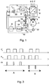
- Fig. 1 illustrates the system of the invention for the compensation of the slip of an asynchronous motor.
- a three-phase asynchronous motor 1 is fed through conductors 2, 4 and 5 by a frequency converter 2, which converts the constant-frequency voltage of the supply network connected to its input terminals R, S and T into a motor supply voltage determined by the control, the frequency and voltage of which are adjustable.
- the frequency converter 2 consists e.g. of a PWM converter 6 and a controller 7 which generates a reference voltage u s and a reference frequency f s for it.
- the speed reference f R for the motor 1 is connected to the reference input of the frequency converter 2 or it is generated within the frequency converter in accordance with external control.
- the signal C compensating the slip of the asynchronous motor is passed via conductor 10 to the control terminal 11 of the frequency converter so that it is summed with the speed reference f R , producing a reference frequency f s .
- the system controlling the frequency converter determines, in a manner known in itself, the magnitude of the motor supply voltage on the basis of the frequency reference.
- the motor speed is measured by means of a pulse sensor 12, which outputs a frequency signal n m proportional to the speed of rotation of the motor.
- the pulse sensor 12 is preferably implemented by providing the motor with an inductive sensor responding to the brake wheel toothing, the cooling ribs of the rotor or e.g. to the fan blades. Thus, no separate tachometer or optic sensor is needed.
- the frequency reference f s of the frequency converter is divided by the number of pole pairs p by a divider 8, and the signal n s obtained from the divider, which is proportional to the synchronous speed of the motor, and the frequency signal n m obtained from the pulse sensor, which is proportional to the speed, are passed to the slip compensator 15 via conductors 13 and 14.
- the output c of the slip compensator 15 is applied to the input of the frequency converter 2 as described above.
- the frequency converter 2, the motor 1 and the speed detector 12 measuring the speed of rotation constitute the outer control loop of the system of the invention, controlling the speed of the motor.
- the slip compensator 15 consists of a summing element 16, a voltage/frequency converter 17, a phase comparator 18 and an integrator 9.
- the frequency signal n m obtained from the pulse sensor 12 is passed via conductor 14 to one of the inputs of the phase comparator 18.
- the synchronous speed n s is obtained as a voltage signal from the frequency converter 2 and passed to the summing element 16, which subtracts from its value the signal ds given by the phase comparator 18.
- the output signal of the summing element 16 is passed to the voltage/frequency converter 17, which forms a frequency signal n s ' corresponding to the reference speed f R of the motor.
- the phase comparator 18 forms a phase difference signal ds on the basis of the phase difference between its input signals n m and n s ' in the manner illustrated by Fig. 3.
- the phase difference signal ds is conveyed to the summing element 16 and to the integrator 9, which generates from the phase difference signal ds a correction signal C, which is applied to the correcting reference input 11 of the frequency converter 2.
- the summing element 16, the voltage-controlled oscillator 17 and the phase comparator 18 constitute the inner loop of the control system, which is structured as a so-called phase-locked loop.
- the speed control system of the invention works as follows.
- the signal n s obtained from the frequency converter 2 is proportional to the output frequency of the frequency converter and to the synchronous speed of the motor.
- the voltage-controlled oscillator 17 produces a frequency signal n s ' proportional to the reference speed of the motor.
- the pulse sensor 12 produces a pulse train n m of a frequency proportional to the speed of rotation of the motor 1.
- the phase comparator 18 compares the pulse trains of signals n s ' and n m . As a result of this comparation, the phase difference signal ds increases if the pulses received from the motor are retarded.
- the phase difference signal ds is subtracted from signal n s , causing the output frequency n s ' of the oscillator 17 to fall and the oscillator to be synchronized with the frequency n m obtained from the pulse sensor.
- the mean value of the phase difference signal causing the synchronization is proportional to the difference between the synchronous speed and the speed of rotation of the motor, i.e. to the slip.
- the integrator 9 generates the correction signal C by filtering the phase difference signal ds.
- a closed speed control circuit is formed which determines the slip of the motor and corrects its supply frequency correspondingly.
- the static state speed of the motor is not dependent on the load but is adjusted to a value corresponding to the reference frequency f R as long as the motor is able to generate a torque corresponding to the load.
- Fig. 2 presents a circuit designed to perform the function of the slip compensator shown in Fig. 1.
- the voltage signal n s (0...10 V) proportional to the motor supply frequency f s is taken through amplifiers 21 and 22 to the voltage-controlled oscillator 23.
- a phase difference signal corresponding to the slip is applied to the summing point at amplifier 22, which subtracts it from the signal n s .
- the oscillator 23 produces at its output a frequency signal n s ' proportional to the reference speed, which is passed to the phase comparator 25.
- the signal n m obtained from the pulse sensor connected to the motor is applied to the other input of the phase comparator.
- the output 26 of the phase comparator 25 is passed to an integrator 27 acting as a filter, whose output gives the correction signal C via amplifier 28.
- the signal ZS keeps the integrator output at zero when the machine has been stopped.
- the phase comparator 25 controls the input of the integrator 27 on the basis of the phase difference between the frequency signals n s ' and n m so that the integrator output increases when the pulse of signal n m lags behind the pulse of signal n s '.
- Fig. 3 represents the input and output pulses of the phase comparator.
- the pulse sensor produces e.g. 24 pulses per revolution, in which case a motor speed of 1800 r/min corresponds to a pulse frequency of 720 Hz.
- the phase comparator is implemented using a CMOS circuit with a three-state output.
- signal n s ' causes the differential signal ds to go into the state +1
- signal n m causes ds to return into the 0-state.
- the pulse duration of ds also increases.
- the pulse of signal nm causes ds to change into the -1-state and the pulse of signal ns' back into the 0-state as is illustrated by the area indicated by arrow B.
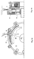
- Fig. 4a shows how the pulse sensor is mounted on the motor.
- the inductive sensor 41 is attached with a fixing element 42 to the body of a brake installed at the end of the motor.
- the brake wheel 43 is provided with a toothing 44 and the sensor is fitted in the immediate vicinity of the teeth.
- Fig. 4b presents a section through Fig. 4a along line A-A.
Landscapes
- Engineering & Computer Science (AREA)
- Power Engineering (AREA)
- Control Of Ac Motors In General (AREA)
- Control Of Electric Motors In General (AREA)
Applications Claiming Priority (2)
| Application Number | Priority Date | Filing Date | Title |
|---|---|---|---|
| FI925710 | 1992-12-16 | ||
| FI925710A FI93061C (fi) | 1992-12-16 | 1992-12-16 | Menetelmä ja laitteisto epätahtikoneen jättämän kompensoimiseksi |
Publications (3)
| Publication Number | Publication Date |
|---|---|
| EP0602490A2 true EP0602490A2 (fr) | 1994-06-22 |
| EP0602490A3 EP0602490A3 (fr) | 1995-02-01 |
| EP0602490B1 EP0602490B1 (fr) | 1997-11-12 |
Family
ID=8536408
Family Applications (1)
| Application Number | Title | Priority Date | Filing Date |
|---|---|---|---|
| EP93119602A Expired - Lifetime EP0602490B1 (fr) | 1992-12-16 | 1993-12-06 | Procédé et dispositif pour compenser le glissement d'une machine à induction |
Country Status (6)
| Country | Link |
|---|---|
| US (1) | US5477121A (fr) |
| EP (1) | EP0602490B1 (fr) |
| JP (1) | JPH06225576A (fr) |
| CA (1) | CA2110465A1 (fr) |
| DE (1) | DE69315180T2 (fr) |
| FI (1) | FI93061C (fr) |
Families Citing this family (6)
| Publication number | Priority date | Publication date | Assignee | Title |
|---|---|---|---|---|
| US5644203A (en) * | 1992-11-10 | 1997-07-01 | Sanyo Seiki Mfg. Co., Ltd. | Brushless motor speed detector |
| US20040070363A1 (en) * | 2002-10-10 | 2004-04-15 | Bardsley David J. | Integrated induction starter/generator system with hybrid control for high speed generation and idle speed smoothing |
| US7424998B1 (en) | 2003-09-22 | 2008-09-16 | John Barney | Motorized lifter |
| KR20130108497A (ko) * | 2010-01-12 | 2013-10-04 | 엠카 레겔테흐닉 아게 | 향상된 효율을 가진 비동기식 모터의 동작 방법 및 장치 |
| JP5563923B2 (ja) * | 2010-07-28 | 2014-07-30 | 本田技研工業株式会社 | 電力変換装置及びモータ駆動制御装置 |
| US10444711B2 (en) * | 2012-04-25 | 2019-10-15 | Sanofi-Aventis Deutschland Gmbh | Apparatus comprising electromechanical device and motion detector and method for operating apparatus |
Family Cites Families (13)
| Publication number | Priority date | Publication date | Assignee | Title |
|---|---|---|---|---|
| CH484566A (de) * | 1967-12-20 | 1970-01-15 | Bosch Gmbh Robert | Einrichtung zum Addieren zweier Impulsfolgen |
| DE2120193C3 (de) * | 1971-04-24 | 1982-02-04 | Robert Bosch Gmbh, 7000 Stuttgart | Digitale Schlupffrequenzregelschaltung für eine umrichtergespeiste Asynchronmaschine |
| US3887853A (en) * | 1973-12-14 | 1975-06-03 | Eaton Corp | Stabilizing system for an inverter-driven induction motor |
| US4044285A (en) * | 1975-08-19 | 1977-08-23 | General Electric Company | Method and apparatus for controlling variable speed, controlled current induction motor drive systems |
| US4358722A (en) * | 1977-08-17 | 1982-11-09 | Kabushiki Kaisha Yaskawa Denki Seisakusho | Speed detector using resolver |
| JPS57199489A (en) * | 1981-05-29 | 1982-12-07 | Hitachi Ltd | Controller for induction motor |
| JPS5886888A (ja) * | 1981-11-16 | 1983-05-24 | Hitachi Ltd | 誘導電動機の制御方式 |
| JPS58119792A (ja) * | 1982-01-11 | 1983-07-16 | Hitachi Ltd | 誘導電動機の制御方法 |
| JPS59156184A (ja) * | 1983-02-23 | 1984-09-05 | Hitachi Ltd | 誘導電動機の制御方法 |
| US4459533A (en) * | 1983-06-03 | 1984-07-10 | Beckman Instruments, Inc. | Variable slip drive system for induction motor |
| JPS6181152A (ja) * | 1984-09-25 | 1986-04-24 | Toshiba Corp | 回転電機の速度センサ−取付装置 |
| JPS62107691A (ja) * | 1985-10-31 | 1987-05-19 | Mitsubishi Electric Corp | 交流電動機の速度制御装置 |
| JPH03270685A (ja) * | 1990-03-16 | 1991-12-02 | Hitachi Ltd | 誘導電動機の制御装置 |
-
1992
- 1992-12-16 FI FI925710A patent/FI93061C/fi not_active IP Right Cessation
-
1993
- 1993-12-01 CA CA002110465A patent/CA2110465A1/fr not_active Abandoned
- 1993-12-06 EP EP93119602A patent/EP0602490B1/fr not_active Expired - Lifetime
- 1993-12-06 DE DE69315180T patent/DE69315180T2/de not_active Expired - Lifetime
- 1993-12-09 US US08/164,696 patent/US5477121A/en not_active Expired - Lifetime
- 1993-12-14 JP JP5342025A patent/JPH06225576A/ja active Pending
Also Published As
| Publication number | Publication date |
|---|---|
| JPH06225576A (ja) | 1994-08-12 |
| EP0602490A3 (fr) | 1995-02-01 |
| DE69315180T2 (de) | 1998-04-09 |
| FI93061B (fi) | 1994-10-31 |
| US5477121A (en) | 1995-12-19 |
| DE69315180D1 (de) | 1997-12-18 |
| FI93061C (fi) | 1995-02-10 |
| EP0602490B1 (fr) | 1997-11-12 |
| FI925710A0 (fi) | 1992-12-16 |
| FI925710L (fi) | 1994-06-17 |
| CA2110465A1 (fr) | 1994-06-17 |
Similar Documents
| Publication | Publication Date | Title |
|---|---|---|
| US5113125A (en) | AC drive with optimized torque | |
| FI71642B (fi) | Reglering av belastningstillstaondet foer en frekvensomformar matad asynkronmotor | |
| US5175483A (en) | Method and an apparatus for computing moment of inertia in a motor speed controller, and a speed control method and apparatus for a motor | |
| EP0490024B1 (fr) | Contrôle vectoriel de moteur asynchrone | |
| EP0602490B1 (fr) | Procédé et dispositif pour compenser le glissement d'une machine à induction | |
| EP3945653A1 (fr) | Détection d'opération d'îlotage | |
| US4721861A (en) | Turbine helper drive apparatus | |
| US3916275A (en) | Accurate motor slip control system with speed rate limited | |
| US3648138A (en) | Arrangement for frequency-analogous speed control of an induction machine fed through an inverter | |
| JPH0410319B2 (fr) | ||
| US4600088A (en) | Apparatus for controlling elevators | |
| EP0446957B1 (fr) | Procédure de régulation de la vitesse de référence d'un moteur à cage commandé en tension | |
| JPH0697880B2 (ja) | 同期機の励磁制御装置 | |
| JP3515389B2 (ja) | ロータリエンコーダの電源供給装置 | |
| US4543513A (en) | Method and an apparatus for controlling a.c. rotating machinery power plants | |
| KR100304790B1 (ko) | 전동기속도제어기 | |
| EP1597818B1 (fr) | Procede et appareil pour regler l'angle de rotor d'un moteur d'ascenseur | |
| JPH08237867A (ja) | 電力変換装置の制御装置 | |
| JPS5915268Y2 (ja) | 電流形インバ−タによる誘導電動機のすべり周波数制御装置 | |
| JPS622899A (ja) | 同期機の乱調・脱調防止方法 | |
| JPH08289597A (ja) | 発電機運転制限装置 | |
| SU1415327A1 (ru) | Способ управлени возбуждением синхронного генератора | |
| SU838996A1 (ru) | Устройство дл управлени частотойВРАщЕНи POTOPA АСиНХРОННОгО элЕКТРОдВигАТЕл | |
| JPS63136997A (ja) | 同期電動機の制御装置 | |
| JPH01186185A (ja) | 駆動電動機の速度制御装置 |
Legal Events
| Date | Code | Title | Description |
|---|---|---|---|
| PUAI | Public reference made under article 153(3) epc to a published international application that has entered the european phase |
Free format text: ORIGINAL CODE: 0009012 |
|
| AK | Designated contracting states |
Kind code of ref document: A2 Designated state(s): DE FR GB IT |
|
| PUAL | Search report despatched |
Free format text: ORIGINAL CODE: 0009013 |
|
| AK | Designated contracting states |
Kind code of ref document: A3 Designated state(s): DE FR GB IT |
|
| 17P | Request for examination filed |
Effective date: 19950629 |
|
| RAP1 | Party data changed (applicant data changed or rights of an application transferred) |
Owner name: KCI KONECRANES INTERNATIONAL CORPORATION |
|
| 17Q | First examination report despatched |
Effective date: 19951221 |
|
| GRAG | Despatch of communication of intention to grant |
Free format text: ORIGINAL CODE: EPIDOS AGRA |
|
| GRAH | Despatch of communication of intention to grant a patent |
Free format text: ORIGINAL CODE: EPIDOS IGRA |
|
| GRAH | Despatch of communication of intention to grant a patent |
Free format text: ORIGINAL CODE: EPIDOS IGRA |
|
| GRAA | (expected) grant |
Free format text: ORIGINAL CODE: 0009210 |
|
| ITF | It: translation for a ep patent filed | ||
| AK | Designated contracting states |
Kind code of ref document: B1 Designated state(s): DE FR GB IT |
|
| REF | Corresponds to: |
Ref document number: 69315180 Country of ref document: DE Date of ref document: 19971218 |
|
| ET | Fr: translation filed | ||
| PLBE | No opposition filed within time limit |
Free format text: ORIGINAL CODE: 0009261 |
|
| STAA | Information on the status of an ep patent application or granted ep patent |
Free format text: STATUS: NO OPPOSITION FILED WITHIN TIME LIMIT |
|
| 26N | No opposition filed | ||
| REG | Reference to a national code |
Ref country code: GB Ref legal event code: IF02 |
|
| PGFP | Annual fee paid to national office [announced via postgrant information from national office to epo] |
Ref country code: GB Payment date: 20121220 Year of fee payment: 20 Ref country code: IT Payment date: 20121217 Year of fee payment: 20 |
|
| PGFP | Annual fee paid to national office [announced via postgrant information from national office to epo] |
Ref country code: DE Payment date: 20121219 Year of fee payment: 20 Ref country code: FR Payment date: 20130123 Year of fee payment: 20 |
|
| REG | Reference to a national code |
Ref country code: DE Ref legal event code: R071 Ref document number: 69315180 Country of ref document: DE |
|
| REG | Reference to a national code |
Ref country code: GB Ref legal event code: PE20 Expiry date: 20131205 |
|
| PG25 | Lapsed in a contracting state [announced via postgrant information from national office to epo] |
Ref country code: DE Free format text: LAPSE BECAUSE OF EXPIRATION OF PROTECTION Effective date: 20131207 Ref country code: GB Free format text: LAPSE BECAUSE OF EXPIRATION OF PROTECTION Effective date: 20131205 |