EP0603832B1 - Dispositif d'appui pour le rattrapage de jeu d'un frein à tambour - Google Patents
Dispositif d'appui pour le rattrapage de jeu d'un frein à tambour Download PDFInfo
- Publication number
- EP0603832B1 EP0603832B1 EP93120629A EP93120629A EP0603832B1 EP 0603832 B1 EP0603832 B1 EP 0603832B1 EP 93120629 A EP93120629 A EP 93120629A EP 93120629 A EP93120629 A EP 93120629A EP 0603832 B1 EP0603832 B1 EP 0603832B1
- Authority
- EP
- European Patent Office
- Prior art keywords
- temperature sensor
- brake
- detector
- shoe web
- shoe
- Prior art date
- Legal status (The legal status is an assumption and is not a legal conclusion. Google has not performed a legal analysis and makes no representation as to the accuracy of the status listed.)
- Expired - Lifetime
Links
Images




Classifications
-
- F—MECHANICAL ENGINEERING; LIGHTING; HEATING; WEAPONS; BLASTING
- F16—ENGINEERING ELEMENTS AND UNITS; GENERAL MEASURES FOR PRODUCING AND MAINTAINING EFFECTIVE FUNCTIONING OF MACHINES OR INSTALLATIONS; THERMAL INSULATION IN GENERAL
- F16D—COUPLINGS FOR TRANSMITTING ROTATION; CLUTCHES; BRAKES
- F16D65/00—Parts or details
- F16D65/38—Slack adjusters
- F16D65/40—Slack adjusters mechanical
- F16D65/52—Slack adjusters mechanical self-acting in one direction for adjusting excessive play
- F16D65/58—Slack adjusters mechanical self-acting in one direction for adjusting excessive play with eccentric or helical body
Definitions
- This invention relates to a drum brake equipped with a device that automatically adjusts shoe clearances, and more specifically relates to a drum brake clearance adjustment staying device that halts this said clearance adjustment when the brake temperature rises.
- a drum brake is generally fitted with an automatic shoe clearance adjustment device.
- This is a device in which a protrusion at one end of a bell crank lever, mounted to pivot on a strut, interlocks in a hole moulded in one shoe web, with a slack in the direction of movement of the brake shoe; and when wear of the brake shoe lining would cause the amount of expansion of the brake shoes to exceed the said slack, the bell crank lever pivots to expand the diameter between the two brake shoes thereby automatically reducing the excess clearance.
- a brake clearance adjustment staying device was developed to resolve this problem, and comprises a flat temperature sensor, which starts to deform at a specified temperature, with its base end riveted to the shoe web and a detector component, bent and molded at the free end of the temperature sensor, interlocking in the hole in which the protrusion of the bell crank lever is inserted; wherein if the brake temperature starts to rise, the detector component of the temperature sensor slips out of the hole in the shoe web and starts to deform in the direction to actually increase the above-mentioned slack.
- the objective of this invention is to provide a drum brake clearance adjustment staying device in which the temperature sensor can easily slip in and out of the shoe web, and wherein the blind movement of the temperature sensor can be regulated.
- a drum brake clearance adjustment staying device as described in the preamble of claim 1 by the feature of the characterizing part.
- a drum brake clearance adjustment staying device comprising these features shows following advantages:
- Figure 1 is a planar diagram of a drum brake.
- Figure 2 is a cross section diagram of Part II-II of Figure 1.
- Figure 3 is an assembly diagram of the temperature sensor.
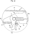
- Figure 4 is an enlarged diagram of the area within the circle indicated by IV in Figure 2.
- Figure 5 is a cross section diagram of part V-V of Figure 1.
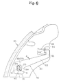
- Figure 6 is a planar diagram to explain the operation of the temperature sensor.
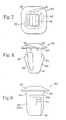
- Figure 7 is a planar diagram of the temperature sensor as observed from the head.
- Figure 8 is a frontal diagram of the temperature sensor.
- Figure 9 is a side diagram of the temperature sensor.
- Figure 10 is an explanatory diagram of another type of temperature sensor as embodied in Example 3.
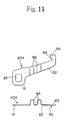
- Figure 11 is an explanatory diagram of another type of temperature sensor as embodied in Example 4.
- Figure 1 and Figure 2 illustrate examples of a drum brake fitted with an automatic shoe clearance adjustment device and a clearance adjustment staying device.
- the back plate 10 is affixed to the vehicle body, and a pair of left and right brake shoes 20, 30 are set inside the said back plate such that they can open and expand.
- Said brake shoes 20, 30 are formed from shoe webs 22, 32 bonded on the inner circumference of arc-shaped rims 21, 31, and friction liners 23, 33 affixed on the external circumference thereof.
- the wheel cylinder 40 that expands the brakes shoes 20, 30, and the anchor 41 that becomes the fulcrum for the brake shoes 20, 30 to expand and contract, are positioned on the upper and lower end respectively inside the back plate 10.
- the upper return spring 50 and lower return spring 51 are tensioned between the brake shoes 20, 30.
- the brake lever 60 penetrates through the back plate 10, wherein one end of the said brake lever pivots at the right end of the strut 70 by means of pin 61 ; the locking arm 62 of the said brake lever 60 interlocks in the hollow hole 34 bored in the shoe web 32 of the brake shoe 30 on the right side of the diagram; the other end of the brake level 60 is connected to a tension cable not shown in the diagram.
- the bell crank lever 72 pivots by means of pin 71 at the left end of the flat strut 70; and the protrusion 72a at one end of the said bell crank lever 72 interlocks in the detector hole 24 bored into the brake shoe 20 on the left side of the diagram.
- the shoe web 32 of the other brake shoe fits into the groove 73 on the right end of the strut 70, and a spring 53 tensioned between the strut 70 and the shoe web 32 constrains any rattling between the two components.
- the toothed edge 72b of the bell crank lever 72 curved radially around the pin 71 meshes with the toothed mating edge 74 on the left side (of diagram) of the strut 70 ; and spring 54 , energized in the direction to mesh the toothed edge 72b with the toothed mating edge 74 is tensioned between the pill 71 and strut 70.
- Figure 3 illustrates the state of the clearance adjustment staying device before assembly into the automatic shoe clearance adjustement device
- Figure 4 illustrates its state after assembly.
- the temperature sensitive component 80 which detects a temperature rise in the brakes and deforms accordingly, is molded from a flat strip of bimetallic or shape-memory alloy or similar metal, and is comprised of a base end 81 affixed to the shoe web 22 of one brake shoe 20, a free end 82 extending from the said base end in the same plane, a hook 83 extending from and in the same plane as the free end 82, and a detector 84 bent at right angles to the flat surface of the hook 83.
- the assembly configuration of the temperature sensor 80 of this invention has been modified as follows.
- the detector 84 of the temperature sensor 80 is inserted into the detector hole 24 in the shoe web 22 so as to abut the side face of protrusion 72a of the bell crank lever 72 , such that a specified slack g is secured at normal temperatures between the detector 84 and the detector hole 24.
- the clip 90 has another function in addition to elastically affixing the base end 81 of the temperature sensor 80 to the shoe web 22 ; as shown in Figure 6, the temperature sensor 80 is energized with a rolational force to pivot around the clip 90 in a counterclockwise direction A (the direction outward from the center of an imaginary circle formed by the pair of brake shoes 20, 30 ).
- the clip 90 was provided with this function for the following reason. Fitting of the clip 90, the mounting hole 85 of the temperature sensor 80, and the mounting hole 25 of the shoe web 22 is such as to cause rattling of the three components, wherein when the temperature falls, the detector 84 of the temperature sensor 80 could get snagged and remain outside of the detector hole 24 . This would create an excessive slack of the protrusion 72a of the bell crank lever 72 inside the detetor hole 24 , and the normal automatic shoe clearance adjustement function will be lost. Thus, to prevent this type of dangerous situation, the clip 90 constantly energizes the detector 84 in the direction to be housed securely within the detector hole 24.
- Figures 5-9 illustrate the clip 90 .
- the clip 90 is comprised of an insertable stem 91 of a cross section shape corresponding to and therefore insertable through the mounting hole 85 in the base end of the temperature sensor 80 and the mounting hole 25 in the shoe web 22, and a head 92 molded of a diameter greater than and glued with resin or other substance on top of the insertable body 91 to form an integrated unit.
- the insertable stem 91 forms a reverse-S in the cross section, and at minimum, the two side faces 91a and 91b facing each other are elastic. These faces must be elastic so that when squeezed for insertion into the mounting holes 85 and 25 , an elastic force (rotational force) will be generated in clip 90. To provide this elastic force the clip 90 should be molded of a dimension such that in its free state, it will be bigger than the said mounting holes 85, 25 .
- an interlocking wedge 93 is molded in the shape of a wedge around the point of symmetry, increasing in thickness in the direction from the bottom towards the head 92.
- This interlocking wedge 93 abuts against the bottom face of the shoe web 22, and functions together with the head 92 to keep the base end 81 of the temperature sensor 80 and the shoe web 22 fitted together.
- the interlocking wedge 93 is not restricted to a two-piece unit as shown in the figure, but can be a 4-piece, or even a 3-or-5-piece unit corresponding to the shape of the mounting holes 25, 85 .
- strips 95 project vertically down from around the circumference of the neck 94 at the top of the insertable stem 91 . These strips 95 reduce the contact resistance between the mounting holes 85 and 25 of the temperature sensor 80 and the shoe web 22 respectively, and facilitate the insertion or removal of the clip 90 , and can be omitted.
- the temperature sensor 80 had to be mounted by rivets or other means onto a specific brake shoe before assembling the brake shoes 20, 30 into the brake assembly.
- the temperature sensor 80 need not be pre-installed onto the brake shoe 20 , but can be installed as follows after the brake shoes 20, 30 are assembled inside the brake assembly.
- the temperature sensor is mounted on the lower face of the brake shoe 20 on the reverse side of the back plate 10 .
- the detector 84 is inserted into the detector hole 24 of the said brake shoe 20.
- the mounting hole 85 of the temperature sensor 80 and the mounting hole 25 of the brake shoe 20 are aligned, and the insertable stem 91 of the clip 90 is inserted until the head 92 presses against the temperature sensor 80, and the interlocking wedge 93 locks onto the lower face of the shoe web 22.
- the base end of the temperature sensor will thus be elastically affixed to the shoe web 22 .
- the temperature sensor 80 receives the rotational force of the clip 90 , the detector 84 at the tip of the temperature sensor 80 abuts the bell crank lever 72 as shown in Figure 4, and a specified slack g ( Figure 4) will be secured between the detector 84 and the detector hole 24 .
- the temperature sensor 80 With its base end 81 as the pivot point as shown in Figure 5, actively moves in the direction to separate from the shoe web 22 of the brake shoe 20 ; and, as shown by the broken line in Figure 4, the detector 84 slips out of the detector hole 24 of the shoe web 22 , wherein the slack of the protrusion 72a of the bell crank lever 72 inside the said detector hole expands.
- the temperature sensor expelled from the detector hole 24 receives the rotational force of the clip 90 and rotates only very slightly around the said clip.
- the state of the detector 84 of the temperature sensor 80 after rotation is shown by the dotted line.
- the temperature sensor 80 deforms in the direction to abut the shoe web 22 of the brake shoe. Since, as shown in Figure 6, the temperature sensor 80 is changing position with receipt of the rotational force of the clip 90 , then the detector 84 returns securely into the detector hole 24 despite a slight looseness between the clip 90 , the mounting hole 85 of the temperature sensor 80 , and the mounting hole 25 of the shoe web 22 .
- a proper tool is used to pinch the interlocking wedge 93 of the clip 90 , and remove the clip 90 in the direction of the head 92 .
- the temperature sensor 80 is then dismounted from the brake shoe 20 .
- the clip 90 need not be glued together with resin as described above, but can for example be of a flat spring or wire spring construction.
- Figure 10 illustrates another embodiment of this invention wherein the clip is molded to the temperature sensor 80a as one integral unit.
- the clip is molded to the temperature sensor 80a as one integral unit.
- the base end 81 of the temperature sensor 80 is molded like a box, but with the two facing sides 81a and 81b extended to form segments 81c and 81d respectively, which are bent backwards to form elastic interlocking components 81e and 81f respectively.
- the upper portion of each interlocking component 81e and 81f is cut away to a specified width in order to abut the underside of the shoe web (not shown in diagram).
- Figure 11 illustrates another temperature sensor in which curves 86 are molded in the body and the free end 82 is bent. The inclusion of these curves 86 lengthens the free end 82 to improve temperature sensitivity.
Landscapes
- Engineering & Computer Science (AREA)
- General Engineering & Computer Science (AREA)
- Mechanical Engineering (AREA)
- Braking Arrangements (AREA)
Claims (3)
- Dispositif d'appui pour le rattrapage de jeu d'un frein à tambour comprenant :caractérisé en ce queun dispositif de réglage de jeu automatique configuré à partir d'un support (70) positionné entre deux garnitures de frein opposées (20, 30) comportant un levier à renvoi (72) monté de manière à pivoter sur une extrémité du support (70), ledit levier à renvoi (72) comportant une saillie (72a) sur une extrémité qui s'emboíte avec un jeu déterminé à l'intérieur d'un orifice de détecteur (24) percé dans un flasque de garniture (22), dans lequel, au cas où la dilatation des garnitures de frein (20, 30) dépasse ledit jeu déterminé, le levier à renvoi (72) pivote afin de régler automatiquement le jeu entre les garnitures de frein (20, 30) et le tambour, etune sonde de température plane (80) configurée de sorte que son extrémité d'embase (81) est montée sur le flasque de garniture (22), et un bord de l'extrémité libre opposée (82) est plié à angles droits de manière à former un détecteur (84) qui s'emboíte dans un orifice de détecteur (24) percé dans ledit flasque de garniture (22), dans lequel, lorsque la température du frein augmente, le détecteur (84) de ladite sonde de température (80) glisse en dehors du flasque de garniture (22) afin de permettre à la sonde de température (80) de se déformer dans un sens destiné à augmenter essentiellement le jeu décrit ci-dessus, et dans lequel, lorsque la température du frein diminue, la sonde de température (80) se déforme dans un sens dirigé vers le flasque de garniture (22),l'extrémité d'embase (81) de la sonde de température (80) est fixée de manière élastique sur ledit flasque de garniture (22) au moyen d'une attache (90), ce qui active le détecteur (84) de la sonde de température (80) par une force de rotation dirigée vers l'extérieur du centre d'un cercle imaginaire formé par la paire de garnitures de frein (20, 30).
- Dispositif d'appui pour le rattrapage de jeu d'un frein à tambour selon la revendication 1, dans lequel ladite attache (90) est formée de manière intégrée à ladite sonde de température (80).
- Dispositif d'appui pour le rattrapage de jeu d'un frein à tambour selon la revendication 1, dans lequel des courbes (86) sont formées dans le corps de la sonde de température (80) de manière à améliorer la sensibilité à la température.
Applications Claiming Priority (2)
| Application Number | Priority Date | Filing Date | Title |
|---|---|---|---|
| JP4355379A JPH06193659A (ja) | 1992-12-21 | 1992-12-21 | ドラムブレーキの間隙調整停止装置 |
| JP355379/92 | 1992-12-21 |
Publications (2)
| Publication Number | Publication Date |
|---|---|
| EP0603832A1 EP0603832A1 (fr) | 1994-06-29 |
| EP0603832B1 true EP0603832B1 (fr) | 1998-03-11 |
Family
ID=18443596
Family Applications (1)
| Application Number | Title | Priority Date | Filing Date |
|---|---|---|---|
| EP93120629A Expired - Lifetime EP0603832B1 (fr) | 1992-12-21 | 1993-12-21 | Dispositif d'appui pour le rattrapage de jeu d'un frein à tambour |
Country Status (4)
| Country | Link |
|---|---|
| US (1) | US5429213A (fr) |
| EP (1) | EP0603832B1 (fr) |
| JP (1) | JPH06193659A (fr) |
| DE (1) | DE69317379T2 (fr) |
Families Citing this family (7)
| Publication number | Priority date | Publication date | Assignee | Title |
|---|---|---|---|---|
| US5992579A (en) * | 1997-08-07 | 1999-11-30 | Meritor Heavy Vehicle Systems, Llc | Method and apparatus for detecting an improperly adjusted slack adjuster |
| GB9822874D0 (en) * | 1998-10-21 | 1998-12-16 | Lucas Ind Plc | Improvements relating to internal shoe drum brakes for vehicles |
| DE19910491A1 (de) * | 1999-03-10 | 2000-09-14 | Continental Teves Ag & Co Ohg | Keilnachstellung mit Thermo-Clip |
| JP3953348B2 (ja) * | 2002-03-27 | 2007-08-08 | 日清紡績株式会社 | ドラムブレーキ |
| JP4096105B2 (ja) * | 2002-09-17 | 2008-06-04 | 日清紡績株式会社 | ブレーキケーブルの接続装置 |
| US8702303B2 (en) | 2011-06-29 | 2014-04-22 | Schneider Electric USA, Inc. | Sensor mounting methodology |
| DE102022208728B3 (de) * | 2022-08-23 | 2023-10-05 | Vitesco Technologies GmbH | Trommelbremse, Bremssystem und Fahrzeug |
Family Cites Families (7)
| Publication number | Priority date | Publication date | Assignee | Title |
|---|---|---|---|---|
| US2570398A (en) * | 1948-03-15 | 1951-10-09 | Thermo Brakes Corp | Automatic adjusting mechanism for brakes |
| FR2285545A1 (fr) * | 1974-09-17 | 1976-04-16 | Dba | Dispositif de rattrapage d'usure sensible a la temperature pour frein a tambour |
| DE3139173A1 (de) * | 1981-10-02 | 1983-04-21 | Volkswagenwerk Ag, 3180 Wolfsburg | "innenbacken-trommelbremse fuer kraftfahrzeuge mit einer mechanischen lueftspiel-nachstellvorrichtung" |
| DE3248015A1 (de) * | 1982-12-24 | 1984-06-28 | Alfred Teves Gmbh, 6000 Frankfurt | Vorrichtung zur nachstellung von bremsbelaegen |
| JPS62292934A (ja) * | 1986-06-10 | 1987-12-19 | Nisshinbo Ind Inc | ドラムブレ−キ |
| JPS6426036A (en) * | 1988-06-22 | 1989-01-27 | Nisshin Spinning | Shoe gap regulating suspension device for drum brake |
| GB9112350D0 (en) * | 1991-06-08 | 1991-07-31 | Gen Motors France | Drum brake and wear adjuster therefor |
-
1992
- 1992-12-21 JP JP4355379A patent/JPH06193659A/ja active Pending
-
1993
- 1993-12-16 US US08/167,345 patent/US5429213A/en not_active Expired - Fee Related
- 1993-12-21 EP EP93120629A patent/EP0603832B1/fr not_active Expired - Lifetime
- 1993-12-21 DE DE69317379T patent/DE69317379T2/de not_active Expired - Fee Related
Also Published As
| Publication number | Publication date |
|---|---|
| JPH06193659A (ja) | 1994-07-15 |
| DE69317379D1 (de) | 1998-04-16 |
| US5429213A (en) | 1995-07-04 |
| DE69317379T2 (de) | 1998-08-06 |
| EP0603832A1 (fr) | 1994-06-29 |
Similar Documents
| Publication | Publication Date | Title |
|---|---|---|
| US4527669A (en) | Friction pad assemblies for use in disc brakes | |
| US4296841A (en) | Antirattle spring for a disc brake of vehicles | |
| EP0603832B1 (fr) | Dispositif d'appui pour le rattrapage de jeu d'un frein à tambour | |
| JPH076565B2 (ja) | ドラムブレ−キ用の感熱ロツク式自動調整ストラツト | |
| EP0388057B1 (fr) | Dispositif d'ajustement automatique pour frein à tambour | |
| GB2147673A (en) | Floating caliper spot-type disc brake | |
| US3983970A (en) | Drum brake | |
| JPS6054531B2 (ja) | デイスクブレ−キ | |
| KR20070065880A (ko) | 마찰 요소 및 디스크 브레이크 | |
| US6196360B1 (en) | Automatic shoe clearance adjustment device for drum brakes | |
| US5159998A (en) | Unispring drum brake assembly | |
| US4216850A (en) | Return spring retention for a vehicle drum brake | |
| US5941356A (en) | Pressure plate assembly for a motor vehicle friction clutch having a wear sensor and a device for protecting the wear sensor during shipment and a method for shipping the pressure plate assembly | |
| EP1432924B1 (fr) | Ensemble frein a tambour | |
| JPS61252926A (ja) | 自動調整装置 | |
| US4533023A (en) | Elastic and sliding locking device for disc brake with a floating caliper supported by a single axial pin, and disc brake equipped with such a device | |
| JPH03500202A (ja) | 特に内側架橋型のスポットタイプディスクブレーキ | |
| EP0398318A2 (fr) | Frein à tambour | |
| AU2002325651A1 (en) | Drum brake assembly | |
| US4196795A (en) | Automatic brake shoe clearance adjusting device | |
| EP1054179A2 (fr) | Dispositif de support de segments pour frein à tambour | |
| US4502573A (en) | Automatic-adjustment drum brake | |
| GB2090928A (en) | Improvements relating to friction pad assemblies for use in disc brakes | |
| JPH0637635U (ja) | ドラムブレーキの間隙調整停止装置 | |
| JP3350796B2 (ja) | ドラムブレーキ装置 |
Legal Events
| Date | Code | Title | Description |
|---|---|---|---|
| PUAI | Public reference made under article 153(3) epc to a published international application that has entered the european phase |
Free format text: ORIGINAL CODE: 0009012 |
|
| AK | Designated contracting states |
Kind code of ref document: A1 Designated state(s): DE FR GB |
|
| 17P | Request for examination filed |
Effective date: 19941110 |
|
| 17Q | First examination report despatched |
Effective date: 19950817 |
|
| GRAG | Despatch of communication of intention to grant |
Free format text: ORIGINAL CODE: EPIDOS AGRA |
|
| RAP1 | Party data changed (applicant data changed or rights of an application transferred) |
Owner name: TOGO SEISAKUSYO CORPORATION Owner name: NISSHINBO INDUSTRIES INC. |
|
| GRAG | Despatch of communication of intention to grant |
Free format text: ORIGINAL CODE: EPIDOS AGRA |
|
| GRAG | Despatch of communication of intention to grant |
Free format text: ORIGINAL CODE: EPIDOS AGRA |
|
| GRAH | Despatch of communication of intention to grant a patent |
Free format text: ORIGINAL CODE: EPIDOS IGRA |
|
| GRAH | Despatch of communication of intention to grant a patent |
Free format text: ORIGINAL CODE: EPIDOS IGRA |
|
| GRAA | (expected) grant |
Free format text: ORIGINAL CODE: 0009210 |
|
| AK | Designated contracting states |
Kind code of ref document: B1 Designated state(s): DE FR GB |
|
| REF | Corresponds to: |
Ref document number: 69317379 Country of ref document: DE Date of ref document: 19980416 |
|
| ET | Fr: translation filed | ||
| PGFP | Annual fee paid to national office [announced via postgrant information from national office to epo] |
Ref country code: FR Payment date: 19981116 Year of fee payment: 6 |
|
| PLBE | No opposition filed within time limit |
Free format text: ORIGINAL CODE: 0009261 |
|
| STAA | Information on the status of an ep patent application or granted ep patent |
Free format text: STATUS: NO OPPOSITION FILED WITHIN TIME LIMIT |
|
| 26N | No opposition filed | ||
| PGFP | Annual fee paid to national office [announced via postgrant information from national office to epo] |
Ref country code: GB Payment date: 19991202 Year of fee payment: 7 |
|
| PGFP | Annual fee paid to national office [announced via postgrant information from national office to epo] |
Ref country code: DE Payment date: 19991230 Year of fee payment: 7 |
|
| PG25 | Lapsed in a contracting state [announced via postgrant information from national office to epo] |
Ref country code: FR Free format text: LAPSE BECAUSE OF NON-PAYMENT OF DUE FEES Effective date: 20000831 |
|
| REG | Reference to a national code |
Ref country code: FR Ref legal event code: ST |
|
| PG25 | Lapsed in a contracting state [announced via postgrant information from national office to epo] |
Ref country code: GB Free format text: LAPSE BECAUSE OF NON-PAYMENT OF DUE FEES Effective date: 20001221 |
|
| GBPC | Gb: european patent ceased through non-payment of renewal fee |
Effective date: 20001221 |
|
| PG25 | Lapsed in a contracting state [announced via postgrant information from national office to epo] |
Ref country code: DE Free format text: LAPSE BECAUSE OF NON-PAYMENT OF DUE FEES Effective date: 20011002 |