EP0606766A1 - Amplificateur de signaux logiques - Google Patents
Amplificateur de signaux logiques Download PDFInfo
- Publication number
- EP0606766A1 EP0606766A1 EP93310548A EP93310548A EP0606766A1 EP 0606766 A1 EP0606766 A1 EP 0606766A1 EP 93310548 A EP93310548 A EP 93310548A EP 93310548 A EP93310548 A EP 93310548A EP 0606766 A1 EP0606766 A1 EP 0606766A1
- Authority
- EP
- European Patent Office
- Prior art keywords
- logic
- signal
- differential
- amplifier
- input
- Prior art date
- Legal status (The legal status is an assumption and is not a legal conclusion. Google has not performed a legal analysis and makes no representation as to the accuracy of the status listed.)
- Withdrawn
Links
- 230000007704 transition Effects 0.000 claims abstract description 9
- 229910044991 metal oxide Inorganic materials 0.000 claims description 3
- 150000004706 metal oxides Chemical class 0.000 claims description 3
- 239000004065 semiconductor Substances 0.000 claims description 3
- 230000005669 field effect Effects 0.000 claims description 2
- 238000010586 diagram Methods 0.000 description 8
- 230000003111 delayed effect Effects 0.000 description 5
- 230000003068 static effect Effects 0.000 description 4
- 230000001934 delay Effects 0.000 description 3
- 230000000295 complement effect Effects 0.000 description 2
- 230000004075 alteration Effects 0.000 description 1
- 230000000694 effects Effects 0.000 description 1
- 238000005516 engineering process Methods 0.000 description 1
- 238000002347 injection Methods 0.000 description 1
- 239000007924 injection Substances 0.000 description 1
- 238000000034 method Methods 0.000 description 1
- 238000012986 modification Methods 0.000 description 1
- 230000004048 modification Effects 0.000 description 1
- 229920006395 saturated elastomer Polymers 0.000 description 1
Images


Classifications
-
- H—ELECTRICITY
- H03—ELECTRONIC CIRCUITRY
- H03K—PULSE TECHNIQUE
- H03K5/00—Manipulating of pulses not covered by one of the other main groups of this subclass
- H03K5/22—Circuits having more than one input and one output for comparing pulses or pulse trains with each other according to input signal characteristics, e.g. slope, integral
- H03K5/24—Circuits having more than one input and one output for comparing pulses or pulse trains with each other according to input signal characteristics, e.g. slope, integral the characteristic being amplitude
- H03K5/2472—Circuits having more than one input and one output for comparing pulses or pulse trains with each other according to input signal characteristics, e.g. slope, integral the characteristic being amplitude using field effect transistors
- H03K5/2481—Circuits having more than one input and one output for comparing pulses or pulse trains with each other according to input signal characteristics, e.g. slope, integral the characteristic being amplitude using field effect transistors with at least one differential stage
-
- H—ELECTRICITY
- H03—ELECTRONIC CIRCUITRY
- H03K—PULSE TECHNIQUE
- H03K19/00—Logic circuits, i.e. having at least two inputs acting on one output; Inverting circuits
- H03K19/003—Modifications for increasing the reliability for protection
- H03K19/00346—Modifications for eliminating interference or parasitic voltages or currents
-
- H—ELECTRICITY
- H03—ELECTRONIC CIRCUITRY
- H03K—PULSE TECHNIQUE
- H03K19/00—Logic circuits, i.e. having at least two inputs acting on one output; Inverting circuits
- H03K19/0175—Coupling arrangements; Interface arrangements
- H03K19/017509—Interface arrangements
- H03K19/017518—Interface arrangements using a combination of bipolar and field effect transistors [BIFET]
- H03K19/017527—Interface arrangements using a combination of bipolar and field effect transistors [BIFET] with at least one differential stage
-
- H—ELECTRICITY
- H03—ELECTRONIC CIRCUITRY
- H03K—PULSE TECHNIQUE
- H03K5/00—Manipulating of pulses not covered by one of the other main groups of this subclass
- H03K5/01—Shaping pulses
- H03K5/02—Shaping pulses by amplifying
- H03K5/023—Shaping pulses by amplifying using field effect transistors
-
- H—ELECTRICITY
- H03—ELECTRONIC CIRCUITRY
- H03K—PULSE TECHNIQUE
- H03K5/00—Manipulating of pulses not covered by one of the other main groups of this subclass
- H03K5/15—Arrangements in which pulses are delivered at different times at several outputs, i.e. pulse distributors
- H03K5/151—Arrangements in which pulses are delivered at different times at several outputs, i.e. pulse distributors with two complementary outputs
Definitions
- the present invention relates to logic amplifiers, and in particular, to logic amplifiers which receive and convert nondifferential logic signals to differential logic signals.
- CMOS complementary metal oxide semiconductor
- CML common mode logic
- ECL emitter-coupled logic
- a conventional logic amplifier 10 for performing this function is shown.
- This amplifier 10 is biased between a positive voltage supply VDD and the circuit reference, i.e. ground GND, and includes an input amplifier 12, current source 14, biasing circuit 16 and output amplifier 18.
- the input amplifier 12 consists of two source-coupled metal oxide semiconductor field effect transistors ("MOSFETs”) M1 and M2 whose drain terminals are tied to VDD by resistors R1 and R2, respectively.
- BJT NPN bipolar junction transistor
- the fixed biasing voltage VB is typically provided by a reference voltage generating circuit called a "bandgap" circuit [not shown] which is powered by the main power supply VDD.
- the biasing circuit 16 produces a fixed biasing voltage VA according to voltage dividing resistors R6 and R7.
- Output amplifier 18 consists of transistor pairs Q4/Q2 and Q5/Q3 which are each coupled in a totem-pole configuration (along with resistors R4 and R5, respectively) and biased by a fixed biasing voltage VD. Parameters and component values for this circuit 10 are summarized below in Table 1.
- the MOSFET M1 receives a single-ended, i.e. nondifferential, CMOS-compatible input signal VIN while MOSFET M2 receives a fixed biased voltage VA established by the voltage divider biasing circuit 16 of resistors R6 and R7.
- the result of these two inputs VIN and VA produce a differential output voltage VD across the drain terminals of MOSFETs M1 and M2.
- the output amplifier 18 receives this differential signal VD and converts it to two nondifferential output signals VOUT and VOUT* which together form the two phases of a differential output signal VOUT-VOUT* (where "X*" indicates a signal which is the inverse phase, i.e. ⁇ 180° [approx.], of signal "X").
- an alternative circuit 20 also includes the input amplifier 12, current source 14 and output amplifier 18, as discussed above.
- the biasing circuit 26 is different in that BJT Q6, biased by the biasing voltage VB, is used to generate the biasing voltage VA (e.g. as an active biasing voltage rather than as the passive biasing voltage generated by the passive biasing circuit 16 of Figure 1).
- VA biasing voltage
- a further alternative circuit 30 also includes the input amplifier 12, current source 14 and output amplifier 18, as discussed above.
- biasing circuit 36 is used for generating the biasing voltage VA.
- Inverter I1 with its input and output terminals connected together produce the biasing voltage VA.
- This type of active voltage divider biasing circuit 36 is well known in the art and is shown in Figure 3A.
- Complementary MOSFETs MP and MN with their source terminals connected to VDD and ground GND, respectively, and their gate and drain terminals all connected together, produce an active biasing voltage VA since both MOSFETs MP and MN are biased on and thereby effectively operate as a voltage divider between VDD and ground.
- the actual DC voltage potential available at the output VA can be preselected by appropriately scaling the device geometries (e.g. the channel widths and lengths) of the two MOSFETs MP and MN. (Parameters and component values for this circuit 30 are summarized above in Table 1.)
- FIG. 4 another conventional circuit 40 has been implemented as an attempt to overcome the above-mentioned problem of static power consumption in the biasing circuits 16, 26, 36.
- this circuit 40 no biasing circuit is used. Rather, the input signal VIN is fed directly to the gate of MOSFET M1, as before, and also to an inverter I1 so as to feed the inverse VIN* of the input signal VIN to the gate of MOSFET M2.
- the input amplifier 12 is now operated as a differential amplifier in that its input signals VIN and VIN* form the two signal phases of a differential input signal VIN-VIN*.
- the two input signals VIN and VIN* should be exactly out of phase and thereby cause MOSFETs M1 and M2 to alternate in their conductance of the biasing current IQ1 provided by the current source 14.
- the MOSFET currents IM1 and IM2 should ideally be exactly out of phase with one another and should each equal the biasing current IQ1.
- the invertor I1 when inverting the input signal VIN to produce its inverse VIN*, introduces a slight time delay t(I1), or phase lag.
- t(I1) time delay
- the output signal currents IM1 and IM2 are also out of phase by t(I1).
- t(I1) no current IQ1 is drawn from the current source 14 and BJT Q1 becomes saturated.
- This causes a perturbation in the voltage VC at the collector of BJT Q1.
- this introduces a noise spike into the biasing voltage VB, which can also affect the output amplifier 18 via BJTs Q2 and Q3.
- the effects of this phase delay t(I1) on the various signals or voltages VIN, VIN*, VOUT, VOUT* and VC can be better understood.
- a logic amplifier in accordance with the present invention includes a differential logic amplifier and an input converter.
- the differential logic amplifier receives a bias current and a differential logic input signal, and in accordance therewith generates a differential logic output signal.
- the differential logic amplifier receives a bias current, a nondifferential logic input signal and a differential logic input signal, and in accordance therewith generates a differential logic output signal.
- the input converter receives the nondifferential logic input signal and converts it to the differential logic input signal for use by the differential logic amplifier.
- the differential logic amplifier includes multiple output signal current paths, each of which is selectively conductive for the differential logic amplifier bias current. At least one of the multiple output signal current paths is conductive for the biasing current uninterruptedly during high-to-low and low-to-high logic transitions of the differential logic input signal.
- At least one of the output signal current paths is conductive for the bias current.
- a bias current source is included to provide the bias current to the differential logic amplifier, and the bias current flows through the differential logic amplifier uninterruptedly during high-to-low and low-to-high logic transitions of the differential logic input signal.
- a bias current source is included to provide the bias current to the differential logic amplifier, and the bias current flows through the differential logic amplifier continuously during the generating of the differential logic output signal.
- Figure 1 is a schematic diagram of a conventional logic amplifier circuit.
- Figure 2 is a schematic diagram of an alternative conventional logic amplifier circuit.
- Figure 3 is a schematic diagram of a further alternative conventional logic amplifier circuit.
- Figure 3A is a schematic diagram of a conventional active voltage divider biasing circuit.
- Figure 4 is a schematic diagram of a still further alternative conventional logic amplifier circuit.
- Figures 5A and 5B depict various signal amplitude and phase relationships for the circuit of Figure 4.
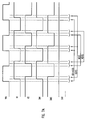
- Figure 6 is a schematic diagram of a logic amplifier in accordance with the present invention.
- Figures 7A and 7B depict various signal amplitude and phase relationships for the circuit of Figure 6.
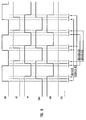
- Figure 8 is a schematic diagram of an alternative preferred embodiment of a logic amplifier in accordance with the present invention.
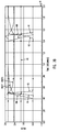
- Figure 9 depicts various signal amplitude and phase relationships for the circuit of Figure 8.
- Figure 10 is a schematic diagram of a further alternative preferred embodiment of a logic amplifier in accordance with the present invention.
- Figure 11 depicts various signal amplitude and phase relationships for the circuit of Figure 10.
- a preferred embodiment 100 of a logic amplifier in accordance with the present invention includes a differential input amplifier 102, current source 104, input converter 106 and output amplifier 108. Circuit parameters and component values are summarized below in Table 2. TABLE 2 Figures 6-8 VDD 3.0 volts dc VB 1.2 volts dc M1 N-MOSFET M2 N-MOSFET M3 ( Figure 8) N-MOSFET Q1 NPN Bipolar Q2 NPN Bipolar Q3 NPN Bipolar Q4 NPN Bipolar Q5 NPN Bipolar R1 20 K ⁇ R2 20 K ⁇ R3 20 K ⁇ R4 30 K ⁇ R5 30 K ⁇ I1 C-MOSFET Inverter I2 ( Figures 7-8) C-MOSFET Inverter I3 ( Figure 7) C-MOSFET Inverter G1 C-MOSFET NAND ( Figure 6) C-MOSFET NOR ( Figure 7) G2 C-MOSFET NAND ( Figure 6) C-MOSFET NOR ( Figure 7)
- the differential input amplifier 102 consists of source-coupled MOSFETs M1 and M2 whose drain terminals are coupled to VDD via resistors R1 and R2 respectively.
- the differential input amplifier 102 receives a bias current IQ1 from the current source 104, which consists of NPN BJT Q1 and resistor R3 biased by a fixed bias voltage VB.
- the differential input amplifier 102 receives a differential input signal V1-V2 (at the gates of MOSFETs M1 and M2) and produces a differential output signal VD (across the drain terminals of MOSFETs M1 and M2).
- the output amplifier 108 receives this differential output signal VD (via the bases of BJTs Q4 and Q5) and produces a differential output signal VOUT-VOUT*.
- the input converter 106 consists of cross-coupled NAND gates G1 and G2 and inverter I1, as shown.
- the nondifferential input signal VIN is converted by the input converter 106 to produce signals V1 and V2 which together, as the signal phases therefor, form the aforementioned differential input signal V1-V2.
- MOSFET M1 when signal V1 is a logical high signal, MOSFET M1 is conductive and output signal current IM1 (MOSFET M1 drain current) flows therethrough.
- MOSFET M2 is conductive and output signal current IM2 (MOSFET M2 drain current) flows therethrough.
- the input signals V1 and V2 have amplitudes and phases relative to one another such that either output signal current IM1 or IM2, or both, flows continuously. This prevents saturation of the current source transistor Q1 and any perturbation in the bias current IQ1 and MOSFETs' source voltage VC.
- Signals V1 and V2, generated from the input signal VIN by the input converter 106 are approximately opposite in phase from one another.
- the leading edge of signal V1 is delayed relative to the leading edge of input VIN by the time delay t(I1+G2) introduced by the inverter I1 and gate G2.
- the leading edge of signal V2 is delayed relative to the leading edge of signal V1 by the time delay t(G1) introduced by gate G1.
- the trailing edge of signal V2 is delayed from the trailing edge of input VIN by the time delay t(G1) introduced by gate G1
- the trailing edge of signal V1 is delayed from the trailing edge of signal V2 by the time delay t(G2) introduced by gate G2.
- the signals V1 and V2 produced by the input converter 106 have duty cycles (positive) which exceed 50%.
- the duty cycles of signals V1 and V2 cause continuous flow of the bias current IQ1 in the form of MOSFET current IM1 or IM2, or in some instances both IM1 and IM2 together.
- MOSFET current IM1 or IM2 flows.
- both IM1 and IM2 flow. Therefore, the bias current IQ1 flows without interruption during all logic transitions (high-to-low and low-to-high) of the input signal VIN.
- the above-discussed amplitude and phase relationships of the signals V1 and V2 produced by the input converter 106 advantageously prevent perturbations in the bias current IQ1 and bias voltage VC. Accordingly, generation and injection of noise spikes into the bias voltage VB, and therefore the output amplifier 108 (via the bases of BJTs Q2 and Q3) is prevented.
- an alternative preferred embodiment 200 of a logic amplifier in accordance with the present invention uses a different form of input converter 206.
- the input converter 206 consists of cross-coupled NOR gates G1, G2, and inverters I1, I2, I3, as shown. Circuit operation for this embodiment 200 is similar to that discussed above for the embodiment 100 shown in Figure 6.
- the relative amplitudes and phases of the signals V1 and V2 produced by the input converter 206 from the input signal VIN are inverse to those for the embodiment 100 of Figure 6.
- the time delays differ somewhat due to the different configuration of gates G1, G2 and inverters I1, I2, I3 used in this particular input converter 206.
- a further alternative preferred embodiment 300 of a logic amplifier in accordance with the present invention uses a different differential input amplifier 302 and input converter 306.
- this differential input amplifier 302 one branch of its output circuit consists of two MOSFETs M2 and M3 connected in parallel.
- MOSFET M3 receives an input signal V3, which is the same as the input signal VIN.
- the MOSFETs M1 and M2 receive their input signals V1 and V2 as output signals from the inverters I1 and I2 which form the input converter 306.
- the relative amplitudes and phases of the various signals VIN, V1, V2 and V3 can be seen. Due to the time delays introduced by the inverters I1 and I2, the leading and trailing edges of signals V1 and V2 are delayed relative to the leading and trailing edge of VIN (and V3).
- a logic amplifier in accordance with the present invention avoids generating noise spikes which occur when a nondifferential signal is converted to a true differential signal.
- an approximate, or quasi, differential signal is first generated in which overlapping signal phases are used to ensure continuous bias current flow, particularly during all logic transitions of the input signal. This advantageously avoids abrupt changes in bias current flow which can generate and inject noise spikes into other signals or circuitry.
- a logic amplifier in accordance with the present invention has an input nondifferential-to-differential signal converter which selectively alters the "lengths" of, i.e. the time delays associated with, the signal paths responsible for generating the differential input signal phases from the nondifferential input signal.
- the signal path which provides the differential input signal phase e.g. V1 [ Figure 6]
- the signal path which provides the differential input signal phase e.g. V1 [ Figure 6]
- V2 inverse differential input signal phase responsible for turning the other branch of the differential amplifier OFF
Landscapes
- Physics & Mathematics (AREA)
- Nonlinear Science (AREA)
- Engineering & Computer Science (AREA)
- Computer Hardware Design (AREA)
- Computing Systems (AREA)
- General Engineering & Computer Science (AREA)
- Mathematical Physics (AREA)
- Logic Circuits (AREA)
- Amplifiers (AREA)
- Electronic Switches (AREA)
Applications Claiming Priority (2)
| Application Number | Priority Date | Filing Date | Title |
|---|---|---|---|
| US08/004,136 US5343094A (en) | 1993-01-13 | 1993-01-13 | Low noise logic amplifier with nondifferential to differential conversion |
| US4136 | 1998-01-07 |
Publications (1)
| Publication Number | Publication Date |
|---|---|
| EP0606766A1 true EP0606766A1 (fr) | 1994-07-20 |
Family
ID=21709350
Family Applications (1)
| Application Number | Title | Priority Date | Filing Date |
|---|---|---|---|
| EP93310548A Withdrawn EP0606766A1 (fr) | 1993-01-13 | 1993-12-24 | Amplificateur de signaux logiques |
Country Status (4)
| Country | Link |
|---|---|
| US (1) | US5343094A (fr) |
| EP (1) | EP0606766A1 (fr) |
| JP (1) | JP3442124B2 (fr) |
| KR (1) | KR100301151B1 (fr) |
Cited By (4)
| Publication number | Priority date | Publication date | Assignee | Title |
|---|---|---|---|---|
| EP0731563A2 (fr) * | 1995-03-10 | 1996-09-11 | Nec Corporation | Porte BICMOS de circuit logique |
| EP0777330A3 (fr) * | 1995-10-31 | 1998-04-08 | STMicroelectronics, Inc. | Tampon PECL |
| EP1248371A1 (fr) * | 2001-04-06 | 2002-10-09 | STMicroelectronics S.r.l. | Convertisseur pour la conversion de niveau des signaux différentiels |
| EP1612941A1 (fr) * | 2004-06-28 | 2006-01-04 | Alcatel | Circuit convertisseur du niveau de puissance |
Families Citing this family (14)
| Publication number | Priority date | Publication date | Assignee | Title |
|---|---|---|---|---|
| US5883538A (en) * | 1996-11-13 | 1999-03-16 | Micron Technology, Inc. | Low-to-high voltage CMOS driver circuit for driving capacitive loads |
| TW265489B (en) * | 1994-07-20 | 1995-12-11 | Micron Technology Inc | Low-to-high voltage cmos driver circuit for driving capacitive loads |
| US5570042B1 (en) * | 1995-01-03 | 2000-10-17 | Sgs Thomson Micro Electronics | Pecl input buffer |
| US5920729A (en) * | 1996-04-30 | 1999-07-06 | Vtc Inc. | Apparatus for providing pair of complementary outputs with first and subcircuits to convert non-complementary and complementary inputs to first and second pair of complementary output |
| US5978379A (en) | 1997-01-23 | 1999-11-02 | Gadzoox Networks, Inc. | Fiber channel learning bridge, learning half bridge, and protocol |
| US7430171B2 (en) | 1998-11-19 | 2008-09-30 | Broadcom Corporation | Fibre channel arbitrated loop bufferless switch circuitry to increase bandwidth without significant increase in cost |
| EP1376867A1 (fr) * | 2002-06-19 | 2004-01-02 | Alcatel | Convertisseur différentiel rapide de logique CMOS en ECL |
| US7019678B1 (en) * | 2005-01-14 | 2006-03-28 | National Semiconductor Corporation | Digital-to-analog converter with constant differential gain and method |
| CN102983852B (zh) * | 2012-11-23 | 2015-01-28 | 深圳市九洲电器有限公司 | 一种差分信号分离器 |
| US12593222B2 (en) | 2022-06-28 | 2026-03-31 | Silicon Laboratories Inc. | Central entity update of configurable receiver front end module between static modes |
| US12218702B2 (en) | 2022-06-28 | 2025-02-04 | Silicon Laboratories Inc. | Providing a single filter for transmit and receive modes |
| US12580601B2 (en) | 2022-06-28 | 2026-03-17 | Silicon Laboratories Inc. | Control of configurable receiver front end module based at least in part on signal metric information |
| US12431929B2 (en) | 2022-06-28 | 2025-09-30 | Silicon Laboratories Inc. | Configurable receiver front end module having configurable detection capabilities |
| US12255678B2 (en) * | 2022-06-28 | 2025-03-18 | Silicon Laboratories Inc. | Interrupt driven reconfiguration of configurable receiver front end module |
Citations (2)
| Publication number | Priority date | Publication date | Assignee | Title |
|---|---|---|---|---|
| US4645951A (en) * | 1983-08-31 | 1987-02-24 | Hitachi, Ltd. | Semiconductor integrated circuit having a C-MOS internal logic block and an output buffer for providing ECL level signals |
| US5117134A (en) * | 1989-08-24 | 1992-05-26 | Nec Corporation | CMOS or TTL to ECL level conversion device |
Family Cites Families (28)
| Publication number | Priority date | Publication date | Assignee | Title |
|---|---|---|---|---|
| FR2272536B1 (fr) * | 1974-05-20 | 1978-02-03 | Tokyo Shibaura Electric Co | |
| US4161663A (en) * | 1978-03-10 | 1979-07-17 | Rockwell International Corporation | High voltage CMOS level shifter |
| US4437171A (en) * | 1982-01-07 | 1984-03-13 | Intel Corporation | ECL Compatible CMOS memory |
| US4532436A (en) * | 1983-09-30 | 1985-07-30 | Rca Corporation | Fast switching circuit |
| US4585958A (en) * | 1983-12-30 | 1986-04-29 | At&T Bell Laboratories | IC chip with noise suppression circuit |
| US4605871A (en) * | 1984-03-12 | 1986-08-12 | Amdahl Corporation | Inverter function logic gate |
| US4703199A (en) * | 1985-04-03 | 1987-10-27 | Intersil, Inc. | Non-restricted level shifter |
| US4656372A (en) * | 1985-11-25 | 1987-04-07 | Ncr Corporation | CMOS to ECL interface circuit |
| US4656375A (en) * | 1985-12-16 | 1987-04-07 | Ncr Corporation | Temperature compensated CMOS to ECL translator |
| JPS62159916A (ja) * | 1986-01-09 | 1987-07-15 | Toshiba Corp | レベル変換回路 |
| US4782250A (en) * | 1987-08-31 | 1988-11-01 | International Business Machines Corporation | CMOS off-chip driver circuits |
| JPH01157121A (ja) * | 1987-09-29 | 1989-06-20 | Toshiba Corp | 論理回路 |
| FI78580C (fi) * | 1987-11-23 | 1989-08-10 | Solitra Oy | Mikrobandkrets och foerfarandet att reglera dess egenskaper. |
| US4982108A (en) * | 1988-08-02 | 1991-01-01 | Motorola, Inc. | Low current CMOS translator circuit |
| JPH0282713A (ja) * | 1988-09-19 | 1990-03-23 | Fujitsu Ltd | スイッチング補助回路 |
| US5047671A (en) * | 1988-10-13 | 1991-09-10 | Ncr Corporation | CMOS to ECL converter |
| US4947061A (en) * | 1989-02-13 | 1990-08-07 | At&T Bell Laboratories | CMOS to ECL output buffer circuit |
| US4978870A (en) * | 1989-07-19 | 1990-12-18 | Industrial Technology Research Institute | CMOS digital level shifter circuit |
| DE3929351C1 (fr) * | 1989-09-04 | 1990-10-11 | Siemens Ag, 1000 Berlin Und 8000 Muenchen, De | |
| JPH03166821A (ja) * | 1989-11-27 | 1991-07-18 | Hitachi Ltd | 半導体集積回路装置 |
| JP2545146B2 (ja) * | 1990-01-25 | 1996-10-16 | 富士通株式会社 | レベル変換回路 |
| US4998028A (en) * | 1990-01-26 | 1991-03-05 | International Business Machines Corp. | High speed CMOS logic device for providing ECL compatible logic levels |
| EP0452675B1 (fr) * | 1990-03-15 | 1996-05-22 | Fujitsu Limited | Circuit tampon pour la conversion de niveaux logiques |
| JP2544826B2 (ja) * | 1990-05-17 | 1996-10-16 | 富士通株式会社 | 半導体集積回路 |
| US5101123A (en) * | 1990-06-29 | 1992-03-31 | Texas Instruments Incorporated | CMOS to ECL translator circuit and methodology |
| US5148059A (en) * | 1991-04-02 | 1992-09-15 | International Business Machines Corporation | CMOS and ECL logic circuit requiring no interface circuitry |
| US5140196A (en) * | 1991-04-15 | 1992-08-18 | Motorola, Inc. | Variable level translator |
| US5132572A (en) * | 1991-08-12 | 1992-07-21 | Advanced Micro Devices, Inc. | High-speed CMOS-to-ECL translator circuit |
-
1993
- 1993-01-13 US US08/004,136 patent/US5343094A/en not_active Expired - Lifetime
- 1993-12-24 EP EP93310548A patent/EP0606766A1/fr not_active Withdrawn
-
1994
- 1994-01-12 JP JP00144794A patent/JP3442124B2/ja not_active Expired - Fee Related
- 1994-01-12 KR KR1019940000380A patent/KR100301151B1/ko not_active Expired - Lifetime
Patent Citations (2)
| Publication number | Priority date | Publication date | Assignee | Title |
|---|---|---|---|---|
| US4645951A (en) * | 1983-08-31 | 1987-02-24 | Hitachi, Ltd. | Semiconductor integrated circuit having a C-MOS internal logic block and an output buffer for providing ECL level signals |
| US5117134A (en) * | 1989-08-24 | 1992-05-26 | Nec Corporation | CMOS or TTL to ECL level conversion device |
Cited By (5)
| Publication number | Priority date | Publication date | Assignee | Title |
|---|---|---|---|---|
| EP0731563A2 (fr) * | 1995-03-10 | 1996-09-11 | Nec Corporation | Porte BICMOS de circuit logique |
| EP0881771A1 (fr) * | 1995-03-10 | 1998-12-02 | Nec Corporation | Porte BiCMOS de circuit logique |
| EP0777330A3 (fr) * | 1995-10-31 | 1998-04-08 | STMicroelectronics, Inc. | Tampon PECL |
| EP1248371A1 (fr) * | 2001-04-06 | 2002-10-09 | STMicroelectronics S.r.l. | Convertisseur pour la conversion de niveau des signaux différentiels |
| EP1612941A1 (fr) * | 2004-06-28 | 2006-01-04 | Alcatel | Circuit convertisseur du niveau de puissance |
Also Published As
| Publication number | Publication date |
|---|---|
| JPH077408A (ja) | 1995-01-10 |
| KR100301151B1 (ko) | 2001-10-22 |
| JP3442124B2 (ja) | 2003-09-02 |
| US5343094A (en) | 1994-08-30 |
| KR940019063A (ko) | 1994-08-19 |
Similar Documents
| Publication | Publication Date | Title |
|---|---|---|
| US5343094A (en) | Low noise logic amplifier with nondifferential to differential conversion | |
| US5621340A (en) | Differential comparator for amplifying small swing signals to a full swing output | |
| US4980579A (en) | ECL gate having dummy load for substantially reducing skew | |
| EP0501085B1 (fr) | Circuit de décalage de niveau pour tampons d'entrée de conversion ECL vers CMOS, réalisés en technologie biCMOS | |
| KR970008836A (ko) | 고속에서 저전류 소모로 저진폭 입력 신호의 증폭이 가능한 입력 버퍼 회로를 포함하는 반도체 소자 | |
| US5202594A (en) | Low power level converter | |
| JP3080793B2 (ja) | インターフェース回路 | |
| KR100332847B1 (ko) | 단일단부입력논리게이트를가진집적논리회로 | |
| JPH10336010A (ja) | Cmlcmos変換回路 | |
| US5485110A (en) | ECL differential multiplexing circuit | |
| EP0529545B1 (fr) | Circuits intégrés CMOS pour décalage de niveau | |
| US5631580A (en) | BICMOS ECL-CMOS level converter | |
| US4868904A (en) | Complementary noise-immune logic | |
| JPH0482319A (ja) | 論理回路 | |
| KR0165986B1 (ko) | BiCMOS 논리 회로 | |
| JP3171927B2 (ja) | 半導体集積回路 | |
| JP2557996B2 (ja) | 相補的エミツタ・フオロワ・ドライバ | |
| US5063310A (en) | Transistor write current switching circuit for magnetic recording | |
| EP0435389B1 (fr) | Multiplexeurs et portes logiques BICMOS à entrées et sorties différentielles et un additionneur utilisant ceux-ci | |
| JP3320757B2 (ja) | 電圧を変換するための装置及び方法 | |
| JPH08139531A (ja) | 差動アンプ | |
| JP2783464B2 (ja) | 半導体集積回路 | |
| JPH09511892A (ja) | 広い電源範囲に亘って動作するのに適した低電圧BiCMOSデジタル遅延チェーン | |
| JP3085433B2 (ja) | レベル変換回路 | |
| JPH06196993A (ja) | Mos型半導体集積回路 |
Legal Events
| Date | Code | Title | Description |
|---|---|---|---|
| PUAI | Public reference made under article 153(3) epc to a published international application that has entered the european phase |
Free format text: ORIGINAL CODE: 0009012 |
|
| AK | Designated contracting states |
Kind code of ref document: A1 Designated state(s): DE FR GB IT NL |
|
| STAA | Information on the status of an ep patent application or granted ep patent |
Free format text: STATUS: THE APPLICATION IS DEEMED TO BE WITHDRAWN |
|
| 18D | Application deemed to be withdrawn |
Effective date: 19950121 |