EP0607552B1 - Dispositif pour réduire les bombements de matière sur un manchon tubulaire d'impression - Google Patents
Dispositif pour réduire les bombements de matière sur un manchon tubulaire d'impression Download PDFInfo
- Publication number
- EP0607552B1 EP0607552B1 EP93119864A EP93119864A EP0607552B1 EP 0607552 B1 EP0607552 B1 EP 0607552B1 EP 93119864 A EP93119864 A EP 93119864A EP 93119864 A EP93119864 A EP 93119864A EP 0607552 B1 EP0607552 B1 EP 0607552B1
- Authority
- EP
- European Patent Office
- Prior art keywords
- cylinder
- circumferential surface
- printing sleeve
- multiplicity
- medium
- Prior art date
- Legal status (The legal status is an assumption and is not a legal conclusion. Google has not performed a legal analysis and makes no representation as to the accuracy of the status listed.)
- Expired - Lifetime
Links
- 238000007639 printing Methods 0.000 title claims description 52
- 239000000463 material Substances 0.000 title claims description 12
- 239000002245 particle Substances 0.000 claims description 9
- 238000007645 offset printing Methods 0.000 claims description 6
- 239000000454 talc Substances 0.000 claims description 2
- 229910052623 talc Inorganic materials 0.000 claims description 2
- 230000037303 wrinkles Effects 0.000 claims 2
- 230000000694 effects Effects 0.000 description 4
- 230000002093 peripheral effect Effects 0.000 description 4
- 239000011324 bead Substances 0.000 description 3
- 238000010276 construction Methods 0.000 description 2
- 238000012986 modification Methods 0.000 description 2
- 230000004048 modification Effects 0.000 description 2
- 230000002411 adverse Effects 0.000 description 1
- 230000007547 defect Effects 0.000 description 1
- 230000003287 optical effect Effects 0.000 description 1
- 230000001141 propulsive effect Effects 0.000 description 1
- 239000000126 substance Substances 0.000 description 1
Images




Classifications
-
- B—PERFORMING OPERATIONS; TRANSPORTING
- B41—PRINTING; LINING MACHINES; TYPEWRITERS; STAMPS
- B41F—PRINTING MACHINES OR PRESSES
- B41F13/00—Common details of rotary presses or machines
- B41F13/08—Cylinders
- B41F13/193—Transfer cylinders; Offset cylinders
-
- B—PERFORMING OPERATIONS; TRANSPORTING
- B41—PRINTING; LINING MACHINES; TYPEWRITERS; STAMPS
- B41F—PRINTING MACHINES OR PRESSES
- B41F13/00—Common details of rotary presses or machines
- B41F13/08—Cylinders
- B41F13/10—Forme cylinders
-
- B—PERFORMING OPERATIONS; TRANSPORTING
- B41—PRINTING; LINING MACHINES; TYPEWRITERS; STAMPS
- B41F—PRINTING MACHINES OR PRESSES
- B41F27/00—Devices for attaching printing elements or formes to supports
- B41F27/10—Devices for attaching printing elements or formes to supports for attaching non-deformable curved printing formes to forme cylinders
- B41F27/105—Devices for attaching printing elements or formes to supports for attaching non-deformable curved printing formes to forme cylinders for attaching cylindrical printing formes
Definitions
- the present invention relates to Offset printing machines and in particular on a device for the reduction of material bulges on one gap-free, tubular pressure sleeve on a cylinder is assembled.
- print images are made of printing plates, which are mounted on plate cylinders, by Transfer cylinder, known as a blanket cylinder, on a transferring moving material web.
- Transfer cylinder known as a blanket cylinder
- Blankets mounted on those blanket cylinders which a rubber surface for the transfer of printed images exhibit.
- Conventional printing plates and blankets are Rectangular in shape and are arranged in axial columns along the circumferential surface of the corresponding Extend plate and blanket cylinder, assembled.
- a number of other problems are to be combined with this design, so that the quality of the final printed product is adversely affected.
- FR-A-2 192 914 shows a printing plate or blanket, which is caused by constant suction air Cylinder is held on the peripheral surface.
- the opposite ends of the printing blanket or the printing plate form a gap, creating an interrupted Surface results, which at high Rotation speeds can lead to vibrations.
- US-A-4,144,813 discloses sleeves which are designed for mounting on one conical core using compressed air be expanded.
- DE-U-85 32 300 shows a roller tube for printing presses an exchangeable casing tube. To build a the elevator of the casing tube with undersize enabling air pressure Before mounting it, a mounting tube on the roller tube postponed.
- a tubular To assemble printing form or a tubular rubber blanket at one end of a corresponding cylinder Air duct is provided on which the sleeve is mounted should.
- the channel delivers through a variety of passages Compressed air radially outwards. While the pressure sleeve over the Is placed in passages, the outflowing compressed air expands the pressure sleeve radially and thus enables the Pressure sleeve on the circumferential surface of the corresponding cylinder is mounted axially.
- This arrangement contains the problem that at the contact point the pressure sleeve and the corresponding cylinder air is included. Generated while the press is running this trapped air is a continuous propulsive wave that precedes the pressure zone between the correspond to cylinders and an adjacent cylinder presses the gap and thus bulges the pressure sleeve causes. This phenomenon is known as pressure sleeve bead. It is caused by defects in the duplication Printed product.
- An object of the present invention is that Device which causes bulges of material Waves of a medium removed to provide.
- the present invention includes the device for connecting the contact surface of the cylinder and the pressure sleeve with a low pressure area the pressure sleeve with at least one groove that runs along whose inner circumferential surface expands through which the enclosed wave of a medium flows out.
- the present invention includes the device for connecting the contact surface of the cylinder and the pressure sleeve with a low pressure area a variety of small, granular particles between which Gaps are formed through which the enclosed Wave of a medium flows out.
- An advantage of the present invention is that the included wave that causes the bulge Medium is removed without affecting the quality of the final Printed product is reduced.
- Another advantage of the present invention is that Doubling is eliminated and thus the overall quality of the final printed product is improved.
- Another advantage of the present invention is that this traps the enclosed wave of a medium can remove several revolutions of the cylinder, so that after Assembling the printing sleeve the printing activity almost immediately can continue.
- Fig. 1 shows a web material 10, which by a Passes gap 12 between a blanket cylinder 14, on which a gap-free, tubular rubber blanket 16 is mounted and an impression cylinder 18 in an offset Printing press. It should be understood that the printing cylinder 18th by another with a rubber blanket Blanket cylinder can be replaced to either side to be able to print the web material 10.
- the rubber blanket 16 transfers print images from a tubular printing form 20, which is mounted on a printing form cylinder 22, on the Web material 10.
- A also forms in the printing form 20 Bulge 30. This is caused by a wave of a Medium 31, which is in front of the gap 28 between the Blanket cylinder 14 and the printing form cylinder 22nd moving forward, caused.
- the waves of one Medium 25, 27 and 31 are created by air, which, during the blanket 16 is mounted on the blanket cylinder 14, is included, or while the printing form 20 on the Printing form cylinder 22 is mounted. This included Compressed air creates bulges 24, 26, and 30 in front of the Columns 28 and 12.
- the shaft of the media 25 continuously moves forward around the blanket cylinder 14, causing the blanket 16 to move relative to the blanket cylinder with each revolution. This movement causes the image transferred to the blanket 16 to be in a different position with each revolution relative to the printing form 20.
- the distance between any given image transferred to the blanket 16 and the latent image of a previous revolution that has been embossed on the blanket causes two images to be printed on the web material 10, that is , doubling takes place. This duplication is an undesirable printing error.
- the 27 and 31 have similar effects.
- the present invention relates to a device for Removal of the waves of a medium directed which the Generate bulges in the blanket 16 and the printing form 20.
- the mentioned invention sees a way before that along the advancing waves of a Medium (trapped air) from below the pressure sleeve, d. i.e., the blanket 16 or the printing form 20, flow out can.
- a Medium trapped air
- the system which constitutes the present invention to Remove any media from the enclosed media Geometry can be applied, which enables the Medium from a contact surface of the pressure sleeve and its corresponding cylinder, d. H. from the blanket cylinder 14 or from the printing form cylinder 22 to an area with a lower pressure than the hydrodynamic pressure in the Waves of the medium can escape.
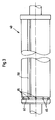
- Fig. 3 represents is such a device that a cylinder 40 with a Has groove 50, which extends over the circumferential Extends surface of the cylinder.
- the groove 50 connects the contact point of the cylinder 40 and one thereon assembled pressure sleeve (not shown) with a Air duct 60.
- the air duct 60 delivers compressed air through the Passages 65 to radially expand the pressure sleeve so that this can be mounted on the cylinder 40. While the Printing machine is running, the air duct 60 can, however Ventilate the atmosphere so that the waves of the medium flow out through the grooves 50 into a low pressure region can.
- Fig. 4 shows a related embodiment, wherein a Cylinder 70 is provided which has a groove 80 which spiral around the circumferential surface of the Rubber blanket cylinder around and across it.
- Figures 3 and 4 are single straight and one single spiral groove can show many such Grooves that can be connected to each other or also not be provided.
- the present invention is also not limited to these configurations.
- the Grooves 50 and 80 can be any type of geometric Configuration and any type of cross-section.
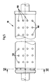
- a cylinder 90 is a plurality of has separate holes 100 that have a contact point of the cylinder 90 and a pressure sleeve 105 mounted thereon (shown in Fig. 6) connect to a low pressure area.
- FIG. 6 shows the plurality of holes 100 formed by the circumferential surface of the cylinder 90 in a channel 110, which opens into the air duct (not shown), lead and which, while the printing press is running, to the atmosphere ventilated, as in the embodiments of Figures 3 and 4 is shown.
- This embodiment is not based on that Arrangement limited, which shown in Figures 5 and 6 becomes. Almost any arrangement of holes can be used and the holes can be any kind of geometric Have configuration.
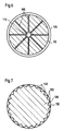
- This embodiment provides a cylinder which has a rough circumferential Surface with one of Maxima 130 and Minima 140 has a certain contour.
- the Maxima 130 and Minima 140 can be made from a variety of cords or roughened be shaped.
- the Minima 140 connect the contact point of the Cylinder 120 and a pressure sleeve 150 mounted thereon an area which has a lower pressure than that of the advancing wave of a medium.
- the Pressure sleeve 150 rides on the Maxima 130 and enables thus the escape of the enclosed waves Medium about the Minima 140.
- a tubular, gap-free pressure sleeve 200 mounted on a cylinder 210 intended.
- the pressure sleeve 200 has a groove 220, which extend along their inner circumferential surface expands.
- the groove 220 connects the contact surface of the Pressure sleeve 200 and the cylinder 210 with a Low pressure area and provides a path along which the enclosed waves of a medium can escape.
- the groove 220 can be any type of geometric Configuration and any type of cross-section. It can also have a variety of such grooves that may or may not be connected to each other, be provided.
- the inner circumferential surface of the Pressure sleeve 200 can also have a rough contour, which is determined by maxima and minima, and in which the enclosed waves of the medium through the minima escape.
- FIG. 9 shows yet another embodiment of the present invention, wherein a tubular gapless pressure sleeve 250 mounted on a cylinder 260 is provided.
- a foreign substance ie small, granular particles 270, such as. B. talc, introduced at the contact point of the pressure sleeve 250 and the cylinder 260.
- the pressure sleeve 250 rests on the small, granular particles 270, which enables the enclosed medium to flow into a low-pressure region via the spaces 280 formed between the particles.
- the small granular particles 270 can have any type of geometric configuration, so that the spaces 280 formed between the particles allow the enclosed medium to flow into a low pressure region.
- the area in which the included Medium flows either the atmosphere, a created one Vacuum or any other area that could be one has lower pressure than the pressure going forward moving waves of a medium.
Landscapes
- Engineering & Computer Science (AREA)
- Mechanical Engineering (AREA)
- Printing Plates And Materials Therefor (AREA)
- Supply, Installation And Extraction Of Printed Sheets Or Plates (AREA)
Claims (29)
- Dispositif destiné à réduire les bombements de matière (24, 26) sur un manchon d'impression (16, 20) tubulaire et sans fente dans une presse offset, les bombements de matière (24, 26) étant Provoqués par au moins une onde (25, 27) d'un fluide se déplaçant vers l'avant et exerçant une pression déterminée, sur un cylindre (14, 22) qui est conçu de façon à loger pour le montage, le manchon d'impression (16, 20) sur sa surface périphérique, caractérisé en ce qu'un dispositif (50, 80, 100 ; 130, 140 ; 220, 270) s'étendant sur la largeur du cylindre (14, 22, 40, 70, 90, 120, 210, 260) est prévu pour assembler un point de contact du cylindre (14, 22, 40, 70, 90, 120, 210, 260) et du manchon d'impression (16, 20, 105, 200, 250) avec une zone qui présente une pression plus basse que celle de l'onde (25, 27) du fluide afin de permettre un écoulement dans la zone à basse pression, de l'onde (25, 27) du fluide qui est bloquée contre le point de contact et se déplace vers l'avant, avant la fente entre le cylindre (14, 22, 40, 70, 90, 120, 210, 260) et un cylindre (18, 22) adjacent.
- Dispositif selon la revendication 1, caractérisé en ce que le dispositif d'assemblage (50, 80, 100 ; 130, 140 ; 220, 270) comprend le cylindre (14, 22, 40, 70, 90, 120, 210, 260) qui présente au moins une gorge ((50) qui s'étend le long de sa surface périphérique et par laquelle s'écoute l'onde (25, 27) bloquée d'un fluide.
- Dispositif selon la revendication 1, caractérisé en ce qu'au moins une gorge (50) s'étend transversalement sur la surface périphérique du cylindre (40).
- Dispositif selon la revendication 2, caractérisé en ce qu'au moins une gorge (80) s'étend en spirale tout autour de la surface périphérique du cylindre (70) et au-delà de la surface périphérique du cylindre (70).
- Dispositif selon la revendication 1, caractérisé en ce que le dispositif d'assemblage (50, 80, 100 ; 130, 140 ; 220, 270) comprend le cylindre (40, 70) avec plusieurs gorges (50, 80) qui s'étendent le long de sa surface périphérique et par lesquelles s'écoute l'onde (25, 27) bloquée d'un fluide.
- Dispositif selon la revendication 5, caractérisé en ce que les gorges (50, 80) sont indépendantes l'une de l'autre.
- Dispositif selon la revendication 5, caractérisé en ce que les gorges (50, 80) sont assemblées entre elles.
- Dispositif selon la revendication 1, caractérisé en ce que le dispositif d'assemblage (50, 80, 100 ; 130, 140 ; 220, 270) comprend le cylindre (90) qui est muni de plusieurs trous (100) par lesquels s'écoule l'onde (25, 27) bloquée d'un fluide.
- Dispositif selon la revendication 8, caractérisé en ce que les trous (100) conduisent de la surface de contact du cylindre (90) et du manchon d'impression (105) à un conduit (110).
- Dispositif selon la revendication 1, caractérisé en ce que le dispositif d'assemblage (50, 80, 100 ; 130, 140 ; 220, 270) comprend le cylindre (120) qui présente une surface périphérique avec un contour rugueux qui est déterminé par des maxima (130) et des minima (140), en ce que le manchon d'impression (150) repose sur les maxima (130) et en ce que l'onde bloquée (25, 27) d'un fluide s'écoule par les minima (140).
- Dispositif selon la revendication 10, caractérisé en ce que les maxima (130) et minima (140) qui déterminent le contour rugueux de la surface périphérique du cylindre (120), sont formés de plusieurs moletages ou rugosités.
- Dispositif selon la revendication 1, caractérisé en ce que le dispositif d'assemblage (50, 80, 100 ; 130, 140 ; 220, 270) comprend le manchon d'impression (210) avec au moins une gorge (220) qui s'étend le long de sa surface périphérique intérieure et par laquelle s'écoule l'onde (25, 27) bloquée d'un fluide.
- Dispositif selon la revendication 12, caractérisé en ce qu'au moins une gorge (220) s'étend transversalement sur la surface périphérique intérieure du manchon d'impression.
- Dispositif selon la revendication 12, caractérisé en ce qu'au moins une gorge (80) s'étend en spirale tout autour de la surface périphérique intérieure du manchon d'impression et au-delà de cette surface.
- Dispositif selon la revendication 1, caractérisé en ce que le dispositif d'assemblage (50, 80, 100 ; 130, 140 ; 220, 270) comprend le manchon d'impression (200) qui présente plusieurs gorges (50, 80, 220) qui s'étendent le long de la surface périphérique interne du manchon d'impression (200) et par lesquelles s'écoule l'onde (25, 27) bloquée d'un fluide.
- Dispositif selon la revendication 15, caractérisé en ce que les gorges (50, 80, 220) sont indépendantes l'une de l'autre.
- Dispositif selon la revendication 15, caractérisé en ce que les gorges (50, 80, 220) sont assemblées entre elles.
- Dispositif selon la revendication 1, caractérisé en ce que le dispositif d'assemblage (50, 80, 100 ; 130, 140 ; 220, 270) comprend le manchon d'impression (150) qui présente une surface périphérique intérieure avec un contour rugueux qui est déterminé par des maxima (130) et des minima (140) et par les creux desquels s'écoule l'onde (25, 27) bloquée d'un fluide.
- Dispositif selon la revendication 18, caractérisé en ce que les maxima (140) et les minima (130) qui déterminent le contour rugueux de la surface périphérique intérieure du manchon d'impression (150), sont formés de plusieurs moletages ou rugosités.
- Dispositif selon la revendication 1, caractérisé en ce que le dispositif d'assemblage (50, 80, 100 ; 130, 140 ; 220, 270) comprend plusieurs petites particules (270) granulaires qui présentent des interstices (280) par lesquels s'écoule l'onde (25, 27) bloquée d'un fluide.
- Dispositif selon la revendication 20, caractérisé en ce que les petites particules (270) granulaires sont du talc.
- Dispositif selon la revendication 1, caractérisé en ce que le manchon d'impression (16, 20, 105, 150, 200, 250) est une forme d'impression tubulaire.
- Dispositif selon la revendication 1, caractérisé en ce que le manchon d'impression (16, 20, 105, 150, 200, 250) est un blanchet tubulaire.
- Dispositif selon la revendication 1, caractérisé en ce que la zone à basse pression est l'atmosphère.
- Dispositif selon la revendication 1, caractérisé en ce que la zone à basse pression est un vide créé.
- Dispositif selon la revendication 1, caractérisé en ce que la zone à basse pression est un conduit de ventilation (60, 65) placé sur le cylindre (40, 70, 90) qui amène l'air comprimé radialement vers l'extérieur pour étendre le manchon d'impression (16, 20, 105, 150, 200, 250) tandis que ce dernier est monté sur le cylindre (40, 70, 90) et qui(conduit de ventilation) ventile vers l'atmosphère pendant le fonctionnement normal de la machine à imprimer.
- Dispositif selon la revendication 1, caractérisé en ce que le cylindre adjacent (22) est un cylindre de la forme d'impression.
- Dispositif selon la revendication 1, caractérisé en ce que le cylindre adjacent (18) est un cylindre d'impression.
- Dispositif selon la revendication 1, caractérisé en ce que le cylindre adjacent (14) est un cylindre porte-blanchet.
Applications Claiming Priority (2)
| Application Number | Priority Date | Filing Date | Title |
|---|---|---|---|
| US745393A | 1993-01-22 | 1993-01-22 | |
| US7453 | 1993-01-22 |
Publications (3)
| Publication Number | Publication Date |
|---|---|
| EP0607552A2 EP0607552A2 (fr) | 1994-07-27 |
| EP0607552A3 EP0607552A3 (fr) | 1995-05-03 |
| EP0607552B1 true EP0607552B1 (fr) | 1998-03-11 |
Family
ID=21726249
Family Applications (1)
| Application Number | Title | Priority Date | Filing Date |
|---|---|---|---|
| EP93119864A Expired - Lifetime EP0607552B1 (fr) | 1993-01-22 | 1993-12-09 | Dispositif pour réduire les bombements de matière sur un manchon tubulaire d'impression |
Country Status (4)
| Country | Link |
|---|---|
| US (1) | US6205923B1 (fr) |
| EP (1) | EP0607552B1 (fr) |
| JP (1) | JP3370167B2 (fr) |
| DE (2) | DE4341262C2 (fr) |
Families Citing this family (16)
| Publication number | Priority date | Publication date | Assignee | Title |
|---|---|---|---|---|
| DE19503095C2 (de) * | 1995-02-01 | 1999-12-16 | Roland Man Druckmasch | Vorrichtung zum Aufspannen einer Hülse auf einen Druckwerkzylinder |
| DE19527761C2 (de) * | 1995-07-28 | 2003-02-27 | Roland Man Druckmasch | Druckwalze zum Befestigen einer Druckhülse |
| DE19536764C2 (de) * | 1995-10-02 | 1998-12-03 | Tampoprint Gmbh | Tamponwalze |
| DE19602289A1 (de) * | 1996-01-23 | 1997-07-24 | Roland Man Druckmasch | Druckvorrichtung |
| DE19602307A1 (de) * | 1996-01-23 | 1997-07-24 | Roland Man Druckmasch | Druckmaschine |
| DE19911965C2 (de) * | 1999-03-17 | 2003-04-30 | Wifag Maschf | Druckform, Verfahren zu ihrer Herstellung und Druckformzylinder für einen Nassoffsetdruck |
| DE10039744B4 (de) * | 2000-08-16 | 2008-06-05 | Hueck Folien Gesellschaft M.B.H. | Spannzylinder zur Aufnahme und Befestigung einer zylindrischen Prägeform mit einer strukturierten Oberfläche |
| AU2003250783A1 (en) * | 2002-07-19 | 2004-03-03 | Koenig And Bauer Aktiengesellschaft | Method and device for reducing vibrations on rotating parts, and vibration-damped rotating part |
| DE502005009727D1 (de) * | 2005-07-18 | 2010-07-22 | Hueck Folien Gmbh | Druckzylinder mit abnehmbarer Prägeform |
| DE102006010551A1 (de) * | 2006-03-07 | 2007-09-13 | Maschinenfabrik Wifag | Entlastungselement |
| DE102006014968A1 (de) * | 2006-03-31 | 2007-10-04 | Man Roland Druckmaschinen Ag | Rotationskörper einer Rollendruckmaschine |
| JP5230932B2 (ja) * | 2006-12-27 | 2013-07-10 | 三菱重工印刷紙工機械株式会社 | 印刷胴用スリーブ、印刷機及び印刷胴用スリーブの内周層着脱方法 |
| JP2009285861A (ja) * | 2008-05-27 | 2009-12-10 | Masayuki Izume | 印刷機用版および印刷機 |
| US8307764B2 (en) * | 2009-02-17 | 2012-11-13 | Luminite Products Corporation | Printing sleeve |
| DE102014101432B3 (de) * | 2014-02-05 | 2014-12-24 | CONPRINTA GmbH & Co. KG | Druckwerk für eine Flexodruckmaschine |
| NL2035249B1 (en) * | 2023-07-03 | 2025-01-10 | Xsys Germany Gmbh | Method for installing a printing plate on a sleeve, the sleeve and assemblies for printing with the printing plate |
Family Cites Families (19)
| Publication number | Priority date | Publication date | Assignee | Title |
|---|---|---|---|---|
| CH122368A (de) * | 1925-09-22 | 1927-09-16 | Maschf Augsburg Nuernberg Ag | Formzylinder für Tiefdruckrotationsmaschinen. |
| CH345023A (de) * | 1955-03-30 | 1960-03-15 | Brackenburry Abell George Edmo | Rotationsdruckmaschine |
| NL207494A (fr) | 1955-06-28 | |||
| DE1292958B (de) * | 1962-12-01 | 1969-04-17 | Saueressig Kg Geb | Walze, insbesondere Druckereiwalze fuer den Textil- und Papierdruck |
| US3640218A (en) * | 1970-06-25 | 1972-02-08 | Thomas K Allison | Seal assembly for sleeve-type gravure rolls |
| GB1401695A (en) * | 1972-07-14 | 1975-07-30 | Precision Printing Equipment W | Cylinder for a printing machine and a method of securing a printing plate to a printing cylinder |
| GB1483371A (en) * | 1974-09-26 | 1977-08-17 | Buckley Ltd M | Printing processes and apparatus |
| IN146438B (fr) * | 1976-01-08 | 1979-06-02 | Strachan & Henshaw Ltd | |
| US4056057A (en) * | 1976-02-27 | 1977-11-01 | Livermore And Knight Co., Inc. | Vacuum printing cylinder construction |
| DE2945280C2 (de) * | 1979-11-09 | 1981-06-11 | M.A.N.- Roland Druckmaschinen AG, 6050 Offenbach | Zylinder für Rotationsdruckmaschinen |
| DE3336193C2 (de) * | 1983-10-05 | 1986-02-27 | M.A.N.- Roland Druckmaschinen AG, 6050 Offenbach | Gummituch für eine Offsetrotationsdruckmaschine |
| EP0278017A1 (fr) * | 1987-02-07 | 1988-08-17 | Saueressig Gmbh & Co. | Cylindre d'impression en creuse comportant un noyau et un manchon amovible |
| EP0196443B1 (fr) * | 1985-03-29 | 1990-05-23 | Saueressig Gmbh & Co. | Cylindre d'impression en creux comportant un noyau et un manchon amovible |
| DE8532300U1 (de) * | 1985-11-15 | 1986-01-02 | Felten & Guilleaume Energietechnik GmbH, 5000 Köln | Walzenrohr für Druckmaschinen mit einem auswechselbaren Mantelrohr |
| DE3543704A1 (de) * | 1985-12-11 | 1987-06-19 | Md Papierfabrik Pasing Nicolau | Vorrichtung und verfahren zum bedrucken einer bahn |
| DE3633155A1 (de) * | 1986-09-30 | 1988-04-07 | Saueressig & Co | Druckzylinder, insbesondere fuer das flexodruckverfahren |
| JPH0818423B2 (ja) * | 1991-03-26 | 1996-02-28 | 三菱重工業株式会社 | オフセット輪転機版胴 |
| US5245923A (en) * | 1992-07-07 | 1993-09-21 | Heidelberg Harris Inc. | Printing press with movable printing blanket |
| DE4432816A1 (de) * | 1994-09-15 | 1996-03-21 | Roland Man Druckmasch | Druckwalze für den kanallosen Druck |
-
1993
- 1993-12-03 DE DE4341262A patent/DE4341262C2/de not_active Expired - Fee Related
- 1993-12-09 DE DE59308252T patent/DE59308252D1/de not_active Expired - Lifetime
- 1993-12-09 EP EP93119864A patent/EP0607552B1/fr not_active Expired - Lifetime
-
1994
- 1994-01-21 JP JP00520494A patent/JP3370167B2/ja not_active Expired - Fee Related
-
1995
- 1995-06-07 US US08/472,354 patent/US6205923B1/en not_active Expired - Fee Related
Also Published As
| Publication number | Publication date |
|---|---|
| JPH071716A (ja) | 1995-01-06 |
| EP0607552A2 (fr) | 1994-07-27 |
| EP0607552A3 (fr) | 1995-05-03 |
| DE4341262C2 (de) | 1999-04-08 |
| JP3370167B2 (ja) | 2003-01-27 |
| US6205923B1 (en) | 2001-03-27 |
| DE59308252D1 (de) | 1998-04-16 |
| DE4341262A1 (de) | 1994-07-28 |
Similar Documents
| Publication | Publication Date | Title |
|---|---|---|
| EP0607552B1 (fr) | Dispositif pour réduire les bombements de matière sur un manchon tubulaire d'impression | |
| DE69809000T2 (de) | Druckmaschine mit auf einem Schlitten montierten austauschbaren Plattenzylindern | |
| EP1361052B1 (fr) | Groupes d'impression d'une machine à imprimer | |
| EP0549936B1 (fr) | Cylindre de transfert avec manchon échangeable, supporté entre deux parois latérales d'un élément d'impression | |
| EP0819550B1 (fr) | Manchon à base de caoutchouc pour machines rotatives offset | |
| EP0421145B2 (fr) | Machine offset | |
| EP0878299B1 (fr) | Machine d'impression rotative à journaux pour bandes | |
| EP1157855B1 (fr) | Manchon à base de caoutchouc, notamment pour machines rotatives offset | |
| DE4337554A1 (de) | Lithographische Offsetdruckmaschine | |
| DD218320A5 (de) | Mehrfarbenrotationsdruckmaschine zum gleichzeitigen schoen- und widerdruck | |
| DE4327646C2 (de) | Breiten-Einstellverfahren für eine Papierbahn sowie damit ausgerüstete lithographische Rotationspresse | |
| DE2033836C3 (de) | Rollen-Rotationsdruckmaschine | |
| DE2736175A1 (de) | Druckwerk | |
| DE2802153C2 (de) | Schmitzringanordnung | |
| DE10006722B4 (de) | Verfahren zum Betreiben einer Offsetdruckmaschine | |
| EP0995596A1 (fr) | Dispositif et procédé pour la mise en oeuvre d'un changement de plaques en marche | |
| EP1767354A2 (fr) | Unité d'impression | |
| DE4401201A1 (de) | Einrichtung zum Festhalten eines bogenförmigen Trägers | |
| DE19848390B4 (de) | Rollenrotationsdruckmaschine für einen schnellen Produktionswechsel | |
| DE3211454C2 (de) | Rollenrotationsdruckmaschine für Endlosdruck | |
| EP1894723B1 (fr) | Arrangement de blanchets sur des cylindres d'une machine d'impression | |
| EP1990191A2 (fr) | Presse d'impression rotative pour bandes | |
| DD281149A5 (de) | Einrichtung zum beseitigen von butzen in mehrfarbendruckmaschinen | |
| EP0826494B2 (fr) | Unité d'impression | |
| DE102005048918B4 (de) | Rollenrotationsdruckmaschine |
Legal Events
| Date | Code | Title | Description |
|---|---|---|---|
| PUAI | Public reference made under article 153(3) epc to a published international application that has entered the european phase |
Free format text: ORIGINAL CODE: 0009012 |
|
| 17P | Request for examination filed |
Effective date: 19931209 |
|
| AK | Designated contracting states |
Kind code of ref document: A2 Designated state(s): CH DE FR GB LI |
|
| GBC | Gb: translation of claims filed (gb section 78(7)/1977) | ||
| PUAL | Search report despatched |
Free format text: ORIGINAL CODE: 0009013 |
|
| AK | Designated contracting states |
Kind code of ref document: A3 Designated state(s): CH DE FR GB LI |
|
| 17Q | First examination report despatched |
Effective date: 19960627 |
|
| GRAG | Despatch of communication of intention to grant |
Free format text: ORIGINAL CODE: EPIDOS AGRA |
|
| GRAG | Despatch of communication of intention to grant |
Free format text: ORIGINAL CODE: EPIDOS AGRA |
|
| GRAH | Despatch of communication of intention to grant a patent |
Free format text: ORIGINAL CODE: EPIDOS IGRA |
|
| GRAH | Despatch of communication of intention to grant a patent |
Free format text: ORIGINAL CODE: EPIDOS IGRA |
|
| GRAA | (expected) grant |
Free format text: ORIGINAL CODE: 0009210 |
|
| AK | Designated contracting states |
Kind code of ref document: B1 Designated state(s): CH DE FR GB LI |
|
| REG | Reference to a national code |
Ref country code: CH Ref legal event code: EP |
|
| REF | Corresponds to: |
Ref document number: 59308252 Country of ref document: DE Date of ref document: 19980416 |
|
| GBT | Gb: translation of ep patent filed (gb section 77(6)(a)/1977) |
Effective date: 19980610 |
|
| ET | Fr: translation filed | ||
| PLBE | No opposition filed within time limit |
Free format text: ORIGINAL CODE: 0009261 |
|
| STAA | Information on the status of an ep patent application or granted ep patent |
Free format text: STATUS: NO OPPOSITION FILED WITHIN TIME LIMIT |
|
| 26N | No opposition filed | ||
| REG | Reference to a national code |
Ref country code: GB Ref legal event code: IF02 |
|
| REG | Reference to a national code |
Ref country code: GB Ref legal event code: 732E |
|
| REG | Reference to a national code |
Ref country code: FR Ref legal event code: TP |
|
| PGFP | Annual fee paid to national office [announced via postgrant information from national office to epo] |
Ref country code: CH Payment date: 20091228 Year of fee payment: 17 |
|
| PGFP | Annual fee paid to national office [announced via postgrant information from national office to epo] |
Ref country code: GB Payment date: 20091229 Year of fee payment: 17 Ref country code: FR Payment date: 20100106 Year of fee payment: 17 |
|
| PGFP | Annual fee paid to national office [announced via postgrant information from national office to epo] |
Ref country code: DE Payment date: 20091230 Year of fee payment: 17 |
|
| REG | Reference to a national code |
Ref country code: CH Ref legal event code: PL |
|
| GBPC | Gb: european patent ceased through non-payment of renewal fee |
Effective date: 20101209 |
|
| REG | Reference to a national code |
Ref country code: FR Ref legal event code: ST Effective date: 20110831 |
|
| PG25 | Lapsed in a contracting state [announced via postgrant information from national office to epo] |
Ref country code: CH Free format text: LAPSE BECAUSE OF NON-PAYMENT OF DUE FEES Effective date: 20101231 Ref country code: LI Free format text: LAPSE BECAUSE OF NON-PAYMENT OF DUE FEES Effective date: 20101231 Ref country code: FR Free format text: LAPSE BECAUSE OF NON-PAYMENT OF DUE FEES Effective date: 20110103 |
|
| REG | Reference to a national code |
Ref country code: DE Ref legal event code: R119 Ref document number: 59308252 Country of ref document: DE Effective date: 20110701 |
|
| PG25 | Lapsed in a contracting state [announced via postgrant information from national office to epo] |
Ref country code: GB Free format text: LAPSE BECAUSE OF NON-PAYMENT OF DUE FEES Effective date: 20101209 Ref country code: DE Free format text: LAPSE BECAUSE OF NON-PAYMENT OF DUE FEES Effective date: 20110701 |