EP0609075A1 - Verbesserungen bezüglich der Herstellung von Flüssigkeitstropfen - Google Patents
Verbesserungen bezüglich der Herstellung von Flüssigkeitstropfen Download PDFInfo
- Publication number
- EP0609075A1 EP0609075A1 EP94300596A EP94300596A EP0609075A1 EP 0609075 A1 EP0609075 A1 EP 0609075A1 EP 94300596 A EP94300596 A EP 94300596A EP 94300596 A EP94300596 A EP 94300596A EP 0609075 A1 EP0609075 A1 EP 0609075A1
- Authority
- EP
- European Patent Office
- Prior art keywords
- nozzle
- liquid
- air
- chamber
- drop
- Prior art date
- Legal status (The legal status is an assumption and is not a legal conclusion. Google has not performed a legal analysis and makes no representation as to the accuracy of the status listed.)
- Withdrawn
Links
- 239000007788 liquid Substances 0.000 title claims abstract description 124
- 238000007599 discharging Methods 0.000 claims description 9
- 239000012530 fluid Substances 0.000 claims description 7
- 238000000034 method Methods 0.000 claims description 4
- 230000001737 promoting effect Effects 0.000 abstract 1
- 230000000694 effects Effects 0.000 description 7
- 239000000758 substrate Substances 0.000 description 7
- 238000009825 accumulation Methods 0.000 description 4
- 230000009977 dual effect Effects 0.000 description 4
- 230000015572 biosynthetic process Effects 0.000 description 3
- 239000011248 coating agent Substances 0.000 description 2
- 238000000576 coating method Methods 0.000 description 2
- 239000011796 hollow space material Substances 0.000 description 2
- 239000000463 material Substances 0.000 description 2
- 230000001133 acceleration Effects 0.000 description 1
- 230000002411 adverse Effects 0.000 description 1
- 230000000712 assembly Effects 0.000 description 1
- 238000000429 assembly Methods 0.000 description 1
- 230000000903 blocking effect Effects 0.000 description 1
- 238000007664 blowing Methods 0.000 description 1
- 239000008187 granular material Substances 0.000 description 1
- 230000000977 initiatory effect Effects 0.000 description 1
- 239000011344 liquid material Substances 0.000 description 1
Images
Classifications
-
- B—PERFORMING OPERATIONS; TRANSPORTING
- B05—SPRAYING OR ATOMISING IN GENERAL; APPLYING FLUENT MATERIALS TO SURFACES, IN GENERAL
- B05B—SPRAYING APPARATUS; ATOMISING APPARATUS; NOZZLES
- B05B1/00—Nozzles, spray heads or other outlets, with or without auxiliary devices such as valves, heating means
- B05B1/02—Nozzles, spray heads or other outlets, with or without auxiliary devices such as valves, heating means designed to produce a jet, spray, or other discharge of particular shape or nature, e.g. in single drops, or having an outlet of particular shape
-
- B—PERFORMING OPERATIONS; TRANSPORTING
- B05—SPRAYING OR ATOMISING IN GENERAL; APPLYING FLUENT MATERIALS TO SURFACES, IN GENERAL
- B05C—APPARATUS FOR APPLYING FLUENT MATERIALS TO SURFACES, IN GENERAL
- B05C11/00—Component parts, details or accessories not specifically provided for in groups B05C1/00 - B05C9/00
- B05C11/10—Storage, supply or control of liquid or other fluent material; Recovery of excess liquid or other fluent material
- B05C11/1002—Means for controlling supply, i.e. flow or pressure, of liquid or other fluent material to the applying apparatus, e.g. valves
- B05C11/1034—Means for controlling supply, i.e. flow or pressure, of liquid or other fluent material to the applying apparatus, e.g. valves specially designed for conducting intermittent application of small quantities, e.g. drops, of coating material
Definitions
- This invention relates to a liquid discharge apparatus, and particularly, to a liquid discharge apparatus which has two stages and is operated to discharge drops in liquid form.
- liquid is discharged in drop form from a liquid discharge apparatus.
- the discharge apparatus is operated in intermittent mode, to facilitate accuracy and control over discharge of the liquid drops.
- One common liquid discharge apparatus for discharging liquids in drop form includes a gun assembly with two stages, an internal stage and an external stage. These stages are defined by axially aligned nozzles, one internal nozzle which receives pressurized liquid and discharges it to a second nozzle, which expels the liquid from the gun assembly under the force of pressurized air supplied thereto. More particularly, operation of a plunger type valve controls the flow of pressurized liquid through a central passageway of the gun assembly to the end of the first, internal nozzle, and intermittent operation of the plunger valve causes the liquid to be discharged intermittently from the internal nozzle.
- each cycle of operation of the plunger valve results in a volume of liquid, preferably a drop, entering into a hollow space between the first and second nozzles. Thereafter, pressurized air is supplied to the hollow space to propel the liquid volume through the external nozzle and out of the gun.
- pressurized air is supplied to the hollow space to propel the liquid volume through the external nozzle and out of the gun.
- this structure is susceptible to inconsistent drop discharge, due to the tendency for liquid to accumulate and/or adhere to the end of the first nozzle when the plunger valve closes. This is particularly true when the liquid has a relatively high viscosity. If liquid adheres to the first nozzle, intermittent operation of the plunger valve will not necessarily produce intermittent discharge of uniform quantities of liquid from the gun. As a result, consistency in drop discharge and uniformity in coating are adversely affected.
- Apparatus for discharging liquid drops in accordance with the invention comprises a gun body having two spaced nozzles, means for supplying liquid to a first nozzle so as to discharge a drop of liquid from the first nozzle towards the inlet of the second nozzle and means for supplying pressurised air to an air chamber surrounding the first nozzle characterised in that the air chamber is in fluid communication with an inlet chamber of reduced cross-sectional area between the outlet of the first nozzle and the inlet of the second nozzle, whereby the flow of air accelerates through the inlet chamber so as to remove adhered liquid from the first nozzle, the pressurised air causing a drop of liquid to be discharged from the second nozzle.
- Such an arrangement improves the consistency in, nd control over, liquid drop discharge for a two stage liquid drop discharge apparatus, and also eliminates problems associated with liquid adherence and/or accumulation to the internal nozzle of a two stage liquid drop discharge apparatus.
- Apparatus in accordance with the invention utilizes a gun assembly having a first internal nozzle that extends into a narrow inlet chamber which leads to the second external nozzle, thus resulting in a region of reduced cross-sectional area, between the first nozzle and the inlet chamber, located intermediate to the upper air chamber of the gun assembly and the second nozzle.
- pressurized air When pressurized air is supplied and flows toward the second nozzle, it produces an acceleration of the air within this region of reduced cross-sectional area, causing active removal of any adhered and/or accummulated liquid from the first internal nozzle.
- the liquid drop falls and covers an entrance to the axially aligned second nozzle, and thereafter the pressurized air discharges the drop therethrough in a "pop gun" effect.
- a liquid drop discharge apparatus includes a gun assembly of interconnected body sections which define a first internal nozzle and a second, axially aligned nozzle for discharging liquid in drop form from the gun.
- the gun includes a plunger valve operated by a solenoid to control intermittent liquid flow through a passage leading to the first nozzle.
- the gun body has an upper air chamber to which pressurized air is supplied and an inlet chamber which leads to the second nozzle.
- the first nozzle extends through from the upper air chamber into the inlet chamber of the second nozzle.
- the plunger valve opens to supply liquid to the first nozzle, with the result that a drop forms at the end of the first nozzle.
- pressurized air is supplied to the upper air chamber within the gun body and flows toward the inlet chamber and the second nozzle, and circumferentially around the outside of the first nozzle in a region of reduced cross-sectional area.
- the flow of this pressurized air through the reduced area region around the first nozzle creates negative pressurization within the inlet chamber, thereby causing the drop formed at the end of the first nozzle and any adhered liquid to fall from the first nozzle to the entrance of the second nozzle, blocking the entrance to the second nozzle.
- pressure generated by the air within the gun builds up and expels the drop through the second nozzle in a pop gun effect.
- Apparatus in accordance with this invention may be used with liquid drop operations wherein the drops are cooled and solidified to form granules, wherein the liquid drops are applied to a surface to be painted, or even in instances where the liquid is atomized and applied.
- the drops may be flattened subsequent to contact with a surface spaced from the end of the second nozzle. In this manner, the flattened drops will form a uniform coating on the surface.
- a second embodiment in accordance with the invention contemplates application of liquid drops within very small regions, such as a surface of an integrated circuit substrate.
- the second nozzle may include a capillary tube.
- the gun body may be configured to provide an additional tube around the outside of the second nozzle tube, thereby to promote removal of liquid from the end of the second nozzle.
- a third embodiment in accordance with the invention uses simplified tubular structures to form the internal nozzle, the inlet chamber and the second nozzle of the gun assembly.
- a fourth embodiment in accordance with the invention uses multiple second nozzles aligned in a row, and each supplied with liquid from an associatd first nozzle. This structure allows the apparatus to coat a pattern of uniform, predetermined width.
- a fifth embodiment in accordance with the invention orients the end of the second nozzle at an angle, suitably 90 degrees, with respect to the first nozzle and the axis of the gun, thereby to allow liquid drops to be discharged in a direction perpendicular to the surface to be coated, i.e. discharged horizontally if used to coat a vertical surface.
- All of these embodiments employ a gun structure wherein the first nozzle extends into an inlet chamber or passage leading to the entrance of the second nozzle. This requires that pressurized air supplied to the second nozzle must pass through the region of reduced cross-sectional area, a region which is created by the size, shape and position of the first nozzle and the inlet chamber.
- an electrical controller may be used to coordinate intermittent operation of the plunger valve for controlling liquid flow from the first nozzle and the supply of pressurized air into the air duct for pop gun discharge of liquid drops from the second nozzle. This assures consistency in operation for each discharge cycle of operation, and preferably results in the discharge of a single liquid drop per cycle.
- apparatus in accordance with the invention does not depend upon the liquid drops adhering to the first nozzle with every cycle of operation. If no liquid adheres to the first nozzle, as may occur when relatively low viscosity liquids are discharged, this same apparatus and mode of operation will produce pop gun expulsion of the liquid through the second nozzle during each cycle of the operation. Thus, the structure performs equally well in consistently discharging liquid drops regardless of whether the liquid is of high, low or medium viscosity.
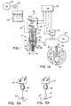
- FIG. 1 shows a first embodiment of a two stage liquid drop discharge apparatus 10 in accordance with the invention.
- the apparatus 10 includes a gun assembly, designated generally by reference numeral 12, which receives pressurized liquid from a tank 14 and discharges the liquid in drop form.
- the liquid in tank 14 is pressurized by a pressure source 16 and controlled by a regulator 18.
- Liquid is supplied to the gun assembly 12 by hose 20.
- the apparatus 10 also uses air pressure to discharge the liquid drops from the nozzle assembly 12. Pressurized air is supplied to the gun assembly 12 via a hose 22, which connects to an air pressure source 24.
- a solenoid valve 26 installed in line 22 controls air flow to the gun assembly 12, and operation of the solenoid valve 26 is controlled by an electrical controller, or timer 28.
- the timer 28 also controls operation of a solenoid 30 mounted to gun assembly 12 to operate a plunger 32. Movement of the plunger 32 opens and closes a liquid duct 34 within gun assembly 12 to permit or prevent, respectively, liquid flow to a first nozzle 36 residing internally of the gun assembly 12.
- the first nozzle 36 is a capillary type nozzle.
- the first nozzle 36 is axially aligned with a second nozzle 38 through which the liquid is discharged from gun assembly 12 in drop form.
- the hose 22 supplying pressurized air to the gun assembly 12 communicates with a pressurized upper air chamber 40 located within gun assembly 12 but external to first nozzle 36.
- the gun assembly 12 includes a first gun body section 42.
- the liquid supply tube 20 connects to body section 42.
- a second gun body section 44 threadably connects to first body section 42.
- First nozzle 36 is defined by a first internal nozzle portion 46, which threadably connects to body section 42 and a second internal nozzle portion 48, which threadably connects to nozzle portion 46, and which terminates at a first nozzle end 37.
- Liquid duct 34 extends through body section 42, first nozzle portion 46 and second nozzle portion 48, which preferably includes a capillary tube.
- plunger 32 is intermittently axially reciprocated away from a valve seat 50 by solenoid 30.
- a second nozzle 38 is formed by a passage 52 formed within the second body section 44 and an external nozzle portion 54 threadably mounted thereto.
- the upper portion of passage 52 is shown in Figure 1A.
- the liquid duct 34 is axially aligned with passage 52.
- the capillary end 37 of first nozzle 36 extends within an inlet chamber 56 which is located between, and in fluid communication with, the pressurized upper air chamber 40 and the passage 52. Inlet chamber 56 is also shown most clearly in Figure 1A.
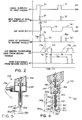
- FIG. 2 shows a chart which illustrates a timing sequence for operating the two stage liquid drop discharge apparatus 10 shown in Figures 1 and 1A.
- the top line, Section A represents intermittent operation of the solenoid 30 and plunger 32 to supply liquid to the first nozzle 36. When "ON", the plunger 32 is raised to allow liquid to flow through duct 34 to the end 37 of first nozzle 36. This is represented by reference numeral 71.
- Section B of Figure 2 illustrates drop formation at the end 37 of first nozzle 36, indicated by reference numeral 72.
- Section C of Figure 2 shows actuation of solenoid 26 via timer 28 to force pressurized air via line 22 into the pressurized air duct 40.
- Reference numeral 73 represents the time lag between closing off liquid flow via plunger 32 and initial supplying of pressurized air to the gun assembly 12, which is represented by reference numeral 74.
- Section D shows drop formation at the entrance 60 to passage 52, represented by reference numeral 75. In most situations, this will occur at a time, designated by reference numeral 76, after initiating the flow of pressurized air. However, in some situations, the liquid drop 61 will not adhere to the first nozzle 36, but will instead fall directly to entrance 60. This situation is shown in Section D via phantom lines, and is represented by reference numeral 75a.
- Section E shows that duration of the supply of accelerated air which is required to cause the drop 61 to move from entrance 60 through passage 52 and out the end of second nozzle 38, in a pop gun effect. This is represented by reference numerals 77 and 77a.
- Section F of Figure 2 shows the time at which the drop 61 is discharged from second nozzle 38. As shown by Sections E and F, regardless of whether the drop 61 falls from first nozzle 36 to entrance 60 on its own or is forced there by air pressure, the time lag 76 before occurrence of pop gun expulsion of the drop 61 remains the same. Thus, for a given liquid material, the total time 78 until the next drop 60 is discharged from gun assembly 12 is the same regardless of whether the drop 60 fell from the first nozzle 36 or was forced therefrom.
- the method and apparatus for two stage liquid drop discharge in accordance with the invention actively prevents liquid accumulation at the end 37 of the first nozzle 36 during intermittent operation, and thereby assures consistency in drop discharge for materials of different viscosities.
- Figures 3A and 3B illustrate another aspect of the invention. More specifically, Figures 3A and 3B show gun assembly 12 when used to discharge liquid drops 61 onto a substrate 65. More specifically, Figure 3A shows drop 61 as it is discharged from second nozzle 38 (in phantom) and as the drop 61 contacts substrate 65. Immediately thereafter, because of the pressurized air supplied through air duct 40, which is expelled through second nozzle 38 toward substrate 65, as shown by directional arrows 80, the drop 61 is flattened by the pressurized air flow which follows the drop 61.
- Figure 4 shows a gun assembly 112 for a two stage liquid drop discharge apparatus constructed in accordance with a second embodiment of the invention.
- the last two digits of the reference numerals correspond to identical structural components of the first embodiment of the invention. This principle also applies for the third, fourth and fifth embodiments.
- Gun assembly 112 is particularly suitable for applying liquid drops in very confined areas, such as a small surface 165 of an electrical component.
- the second nozzle 138 includes an elongated, capillary portion 154.
- the second gun body section 144 includes an air flow passage 145 which communicates with an internal space 147 external to portion 154 and internal to an external tube 149 which is shown in phantom lines.
- the second nozzle 138 contains a dual tube assembly, with a capillary inner tube 154 residing within the external tube 149. This permits air flow between the tubes 154 and 149 along internal passage 147, since passage 145 is in communication with upper air chamber 140.
- This structure prevents liquid drops 61 from adhering to the end of second nozzle 138 and may also atomize the drops 161 as they are discharged toward surface 165, depending on their viscosity.
- the second nozzle 138 may be bent to more readily accommodate directing the discharged drops 161a toward a surface 165a to be coated.
- the nozzle 138 is bent at a 90 degree angle with respect to the gun 112.
- FIG. 5 shows a gun assembly 212 for a two stage liquid drop discharge apparatus constructed in accordance with a third embodiment of the invention.
- the structure for supporting the second nozzle 238 is designed as a tube, for structural simplicity.
- the gun 212 includes a first outer tube 239 connected to gun body section 246 and a second, reduced diameter tube 241 connected to tube 239.
- the reduced diameter tube 241 has a narrowed portion 243 to define the exit passage 252 from the second nozzle 238.
- This gun assembly 212 operates in the same manner as gun assemblies 12 and 112 described above.
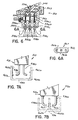
- FIG. 6 shows a gun assembly 312 for a two stage liquid drop discharge apparatus constructed in accordance with a fourth embodiment of the invention.
- This embodiment contemplates simultaneous discharge of drops from multiple sites.
- liquid duct 334 branches into three separate passages 334a, 334b and 334c, downstream of plunger 332. These passages 334a, 334b and 334c terminate at the ends of first nozzles 336a, 336b and 336c, respectively. These first nozzles reside above passages 352a, 352b and 352c, respectively, of second nozzles 338a, 338b, and 338c.
- a second body section 344 is secured to first body section 342 via a clamp 345.
- This gun assembly 312 is operated in the same manner as described previously with respect to the other embodiments, but this gun assembly 312 produces a wider discharge pattern, as shown in Figure 6A, wherein a pattern 367 is formed by flattened drops 361a, 361b and 361c. If desired, the number of discharge sites may be further increased, or varied, depending on the desired width, or shape, of the pattern to be coated.
- Figures 7A and 7B show two variations for a gun assembly 412 of a two stage liquid drop discharge apparatus constructed in accordance with a fifth embodiment of the invention.
- an article 485 to be coated is U-shaped, and dual second nozzles 438a and 438b are turned outwardly at 90 degrees to discharge drops toward vertical inside surfaces 465a and 465b of the article 485, respectively.
- article 486 is E-shaped with the openings and legs of the E directed upwardly.
- dual second nozzles 438a and 438b are directed inwardly at 90 degrees to dispense material onto oppositely directed vertical surfaces 465a and 465b, respectively, of the inside leg of the E-shaped article 486.
- the dual second nozzles 438a and 438b may be made rotatable to enable a single gun assembly 412 to be used to dischare liquid drops in the manner shown in Figures 7A and 7B.
- All of the embodiments of the invention rely upon the same principal, that of accelerating the discharge air through a narrow space around an internal first nozzle to prevent liquid from adhering thereto after liquid flow has been intermittently stopped.
- the size and location of the first nozzle with respect to the upper air chamber and the inlet chamber of the second nozzle results in a reduced cross-sectional area between the first nozzle and the body of the second nozzle, thereby accelerating the air therethrough and producing a Bernoulli effect which removes the drops from the end of the first nozzle.
- the drop or drops fall and cover the opening of the second nozzle in axial alignment therewith, and thereafter the pressurized air discharges the drop through the second nozzle in a pop gun effect.
Landscapes
- Nozzles (AREA)
- Application Of Or Painting With Fluid Materials (AREA)
- Coating Apparatus (AREA)
- Glanulating (AREA)
Applications Claiming Priority (2)
| Application Number | Priority Date | Filing Date | Title |
|---|---|---|---|
| JP03262493A JP3303217B2 (ja) | 1993-01-28 | 1993-01-28 | 二流体による二段式液滴吐出又はそれによる造粒、塗布の各方法及びそれらのノズル組立体 |
| JP32624/93 | 1993-01-28 |
Publications (1)
| Publication Number | Publication Date |
|---|---|
| EP0609075A1 true EP0609075A1 (de) | 1994-08-03 |
Family
ID=12364013
Family Applications (1)
| Application Number | Title | Priority Date | Filing Date |
|---|---|---|---|
| EP94300596A Withdrawn EP0609075A1 (de) | 1993-01-28 | 1994-01-27 | Verbesserungen bezüglich der Herstellung von Flüssigkeitstropfen |
Country Status (2)
| Country | Link |
|---|---|
| EP (1) | EP0609075A1 (de) |
| JP (1) | JP3303217B2 (de) |
Cited By (6)
| Publication number | Priority date | Publication date | Assignee | Title |
|---|---|---|---|---|
| WO2007006509A1 (de) * | 2005-07-14 | 2007-01-18 | Max-Planck Gesellschaft Zur Foerderung Der Wissenschaften E.V. | Düsenanordnung |
| CN103301970A (zh) * | 2013-04-10 | 2013-09-18 | 上海大学 | 液体注入式微点雾喷射装置 |
| CN104148242A (zh) * | 2014-08-27 | 2014-11-19 | 江汉大学 | 用于液滴细分的同轴双孔针头、装置及方法 |
| CN105750550A (zh) * | 2016-04-02 | 2016-07-13 | 上海大学 | 数字喷射雾化沉积装置 |
| CN108096027A (zh) * | 2017-11-28 | 2018-06-01 | 浙江安宝药业有限公司 | 软胶囊机及软胶囊成型方法 |
| US12179229B2 (en) | 2018-11-22 | 2024-12-31 | Illinois Tool Works Inc. | Nozzle |
Families Citing this family (2)
| Publication number | Priority date | Publication date | Assignee | Title |
|---|---|---|---|---|
| US6811096B2 (en) * | 2002-12-30 | 2004-11-02 | Aqua Glass Corporation | Spray gun with internal mixing structure |
| KR102084595B1 (ko) * | 2018-01-26 | 2020-03-04 | (주)엔에스 | 주입 노즐 어셈블리 |
Citations (5)
| Publication number | Priority date | Publication date | Assignee | Title |
|---|---|---|---|---|
| EP0158485A2 (de) * | 1984-04-05 | 1985-10-16 | Mobil Oil Corporation | Vorrichtung zur Erzeugung von Tröpfchen |
| US4629478A (en) * | 1984-06-22 | 1986-12-16 | Georgia Tech Research Corporation | Monodisperse aerosol generator |
| JPS63100965A (ja) * | 1986-05-30 | 1988-05-06 | Nordson Kk | 二流体スプレイ方法 |
| US4941428A (en) * | 1987-07-20 | 1990-07-17 | Engel Harold J | Computer controlled viscous material deposition apparatus |
| EP0478448A1 (de) * | 1990-09-27 | 1992-04-01 | Commissariat A L'energie Atomique | Pneumatischer Vernebler |
-
1993
- 1993-01-28 JP JP03262493A patent/JP3303217B2/ja not_active Expired - Lifetime
-
1994
- 1994-01-27 EP EP94300596A patent/EP0609075A1/de not_active Withdrawn
Patent Citations (5)
| Publication number | Priority date | Publication date | Assignee | Title |
|---|---|---|---|---|
| EP0158485A2 (de) * | 1984-04-05 | 1985-10-16 | Mobil Oil Corporation | Vorrichtung zur Erzeugung von Tröpfchen |
| US4629478A (en) * | 1984-06-22 | 1986-12-16 | Georgia Tech Research Corporation | Monodisperse aerosol generator |
| JPS63100965A (ja) * | 1986-05-30 | 1988-05-06 | Nordson Kk | 二流体スプレイ方法 |
| US4941428A (en) * | 1987-07-20 | 1990-07-17 | Engel Harold J | Computer controlled viscous material deposition apparatus |
| EP0478448A1 (de) * | 1990-09-27 | 1992-04-01 | Commissariat A L'energie Atomique | Pneumatischer Vernebler |
Non-Patent Citations (1)
| Title |
|---|
| PATENT ABSTRACTS OF JAPAN vol. 12, no. 344 (C - 528) 16 September 1988 (1988-09-16) * |
Cited By (8)
| Publication number | Priority date | Publication date | Assignee | Title |
|---|---|---|---|---|
| WO2007006509A1 (de) * | 2005-07-14 | 2007-01-18 | Max-Planck Gesellschaft Zur Foerderung Der Wissenschaften E.V. | Düsenanordnung |
| CN103301970A (zh) * | 2013-04-10 | 2013-09-18 | 上海大学 | 液体注入式微点雾喷射装置 |
| CN103301970B (zh) * | 2013-04-10 | 2016-03-30 | 上海大学 | 液体注入式微点雾喷射装置 |
| CN104148242A (zh) * | 2014-08-27 | 2014-11-19 | 江汉大学 | 用于液滴细分的同轴双孔针头、装置及方法 |
| CN105750550A (zh) * | 2016-04-02 | 2016-07-13 | 上海大学 | 数字喷射雾化沉积装置 |
| CN105750550B (zh) * | 2016-04-02 | 2018-08-03 | 上海大学 | 数字喷射雾化沉积装置 |
| CN108096027A (zh) * | 2017-11-28 | 2018-06-01 | 浙江安宝药业有限公司 | 软胶囊机及软胶囊成型方法 |
| US12179229B2 (en) | 2018-11-22 | 2024-12-31 | Illinois Tool Works Inc. | Nozzle |
Also Published As
| Publication number | Publication date |
|---|---|
| JP3303217B2 (ja) | 2002-07-15 |
| JPH06218312A (ja) | 1994-08-09 |
Similar Documents
| Publication | Publication Date | Title |
|---|---|---|
| JP4014693B2 (ja) | 改良型スプレー・ノズルで液体被覆を塗布する方法および装置 | |
| US7621466B2 (en) | Nozzle for cold spray and cold spray apparatus using same | |
| FI84459C (fi) | Tryckreglare innefattande en monteringskammare. | |
| US4835819A (en) | Coated fasteners and process for making the same | |
| US5074466A (en) | Fluid valve stem for air spray gun | |
| KR100231240B1 (ko) | 개량된 플랫 팬 스프레이 노즐 | |
| US4778642A (en) | Sealant bead profile control | |
| US5478224A (en) | Apparatus for depositing a material on a substrate and an applicator head therefor | |
| JP2992760B2 (ja) | ノズル孔より流出する液体又は溶融体をその周辺よりの気体噴出流により偏向分配する方法 | |
| US6170760B1 (en) | Compact spray valve | |
| EP0609075A1 (de) | Verbesserungen bezüglich der Herstellung von Flüssigkeitstropfen | |
| CN1397381A (zh) | 喷枪 | |
| EP1987886A2 (de) | Düse für Spritzpistolen | |
| US3301488A (en) | Spray gun | |
| EP0589075A1 (de) | Luftleitring für die Luftkappe einer Spritzpistole | |
| JPH04227873A (ja) | 静電噴射装置 | |
| NL2021704B1 (en) | Spray device, nozzle unit and nozzle body | |
| JPH03267164A (ja) | 塗装方法および塗装装置 | |
| JPH05104038A (ja) | 媒体用排出ノズル | |
| CA1187355A (en) | Method of fuel injection | |
| JPH08141455A (ja) | 塗装ガン洗浄装置 | |
| EP0819473A1 (de) | Verfahren und Vorrichtung zum Auftragen eines flüssigen Beschichtungsmittels in atomisierter oder nichtatomisierter Form mittels einer einzigen Düse | |
| JP3122819B2 (ja) | ノズル孔より流出する液体又は溶融体をその周辺よりの気体噴出流により偏向分配する方法 | |
| JP4174760B2 (ja) | 中空立体形状被塗物の内面への液体又は溶融体の塗布方法 | |
| KR20010070321A (ko) | 노즐 |
Legal Events
| Date | Code | Title | Description |
|---|---|---|---|
| PUAI | Public reference made under article 153(3) epc to a published international application that has entered the european phase |
Free format text: ORIGINAL CODE: 0009012 |
|
| AK | Designated contracting states |
Kind code of ref document: A1 Designated state(s): DE FR GB IT |
|
| 17P | Request for examination filed |
Effective date: 19950109 |
|
| STAA | Information on the status of an ep patent application or granted ep patent |
Free format text: STATUS: THE APPLICATION HAS BEEN WITHDRAWN |
|
| 18W | Application withdrawn |
Withdrawal date: 19950622 |