EP0613124A2 - Tête actionnée électrostatiquement et résistante aux chocs pour l'enregistrement et lecture optique - Google Patents
Tête actionnée électrostatiquement et résistante aux chocs pour l'enregistrement et lecture optique Download PDFInfo
- Publication number
- EP0613124A2 EP0613124A2 EP94300766A EP94300766A EP0613124A2 EP 0613124 A2 EP0613124 A2 EP 0613124A2 EP 94300766 A EP94300766 A EP 94300766A EP 94300766 A EP94300766 A EP 94300766A EP 0613124 A2 EP0613124 A2 EP 0613124A2
- Authority
- EP
- European Patent Office
- Prior art keywords
- actuator
- wafers
- linear actuator
- housing
- longitudinally
- Prior art date
- Legal status (The legal status is an assumption and is not a legal conclusion. Google has not performed a legal analysis and makes no representation as to the accuracy of the status listed.)
- Granted
Links
Images


Classifications
-
- H—ELECTRICITY
- H02—GENERATION; CONVERSION OR DISTRIBUTION OF ELECTRIC POWER
- H02N—ELECTRIC MACHINES NOT OTHERWISE PROVIDED FOR
- H02N1/00—Electrostatic generators or motors using a solid moving electrostatic charge carrier
- H02N1/002—Electrostatic motors
- H02N1/006—Electrostatic motors of the gap-closing type
-
- G—PHYSICS
- G11—INFORMATION STORAGE
- G11B—INFORMATION STORAGE BASED ON RELATIVE MOVEMENT BETWEEN RECORD CARRIER AND TRANSDUCER
- G11B7/00—Recording or reproducing by optical means, e.g. recording using a thermal beam of optical radiation by modifying optical properties or the physical structure, reproducing using an optical beam at lower power by sensing optical properties; Record carriers therefor
- G11B7/08—Disposition or mounting of heads or light sources relatively to record carriers
- G11B7/09—Disposition or mounting of heads or light sources relatively to record carriers with provision for moving the light beam or focus plane for the purpose of maintaining alignment of the light beam relative to the record carrier during transducing operation, e.g. to compensate for surface irregularities of the latter or for track following
- G11B7/0925—Electromechanical actuators for lens positioning
- G11B7/093—Electromechanical actuators for lens positioning for focusing and tracking
-
- G—PHYSICS
- G11—INFORMATION STORAGE
- G11B—INFORMATION STORAGE BASED ON RELATIVE MOVEMENT BETWEEN RECORD CARRIER AND TRANSDUCER
- G11B7/00—Recording or reproducing by optical means, e.g. recording using a thermal beam of optical radiation by modifying optical properties or the physical structure, reproducing using an optical beam at lower power by sensing optical properties; Record carriers therefor
- G11B7/08—Disposition or mounting of heads or light sources relatively to record carriers
- G11B7/09—Disposition or mounting of heads or light sources relatively to record carriers with provision for moving the light beam or focus plane for the purpose of maintaining alignment of the light beam relative to the record carrier during transducing operation, e.g. to compensate for surface irregularities of the latter or for track following
- G11B7/0925—Electromechanical actuators for lens positioning
- G11B7/0932—Details of sprung supports
-
- G—PHYSICS
- G11—INFORMATION STORAGE
- G11B—INFORMATION STORAGE BASED ON RELATIVE MOVEMENT BETWEEN RECORD CARRIER AND TRANSDUCER
- G11B7/00—Recording or reproducing by optical means, e.g. recording using a thermal beam of optical radiation by modifying optical properties or the physical structure, reproducing using an optical beam at lower power by sensing optical properties; Record carriers therefor
- G11B7/08—Disposition or mounting of heads or light sources relatively to record carriers
- G11B7/09—Disposition or mounting of heads or light sources relatively to record carriers with provision for moving the light beam or focus plane for the purpose of maintaining alignment of the light beam relative to the record carrier during transducing operation, e.g. to compensate for surface irregularities of the latter or for track following
- G11B7/0925—Electromechanical actuators for lens positioning
- G11B7/0935—Details of the moving parts
-
- G—PHYSICS
- G11—INFORMATION STORAGE
- G11B—INFORMATION STORAGE BASED ON RELATIVE MOVEMENT BETWEEN RECORD CARRIER AND TRANSDUCER
- G11B7/00—Recording or reproducing by optical means, e.g. recording using a thermal beam of optical radiation by modifying optical properties or the physical structure, reproducing using an optical beam at lower power by sensing optical properties; Record carriers therefor
- G11B7/08—Disposition or mounting of heads or light sources relatively to record carriers
- G11B7/09—Disposition or mounting of heads or light sources relatively to record carriers with provision for moving the light beam or focus plane for the purpose of maintaining alignment of the light beam relative to the record carrier during transducing operation, e.g. to compensate for surface irregularities of the latter or for track following
- G11B7/0925—Electromechanical actuators for lens positioning
- G11B7/0937—Piezoelectric actuators
Definitions
- the present invention relates to the field of optical recording and reproduction of information on optical disks and similar optical information storage media. More particularly, the invention relates to an improved shock-resistant pick-up apparatus for directing radiant energy onto precisely controllable locations of an optically sensitive recording medium to record information on the medium, and/or to reproduce information previously recorded on the medium.
- Video disks using pulse width modulated (PWM) and pulse code modulated (PCM) signals containing audio, video, alphanumeric information, as well as binary encoded data in general, are in common use.
- Video disk systems use an electro-optical device, usually called a pick-up, to focus on and track information-containing regions of the disk, in which information bits are recorded by altering an optical property of the disk.
- Individual bits of bi-directional information may be recorded in spaces having a maximum dimension of less than 1 micron.
- these regions are arranged in the form of a continuous spiral track, or a series of concentric tracks, containing a string of bits.
- Precise tracking is required to select a track, or to maintain a selected track, or portion of a track, within the optical field of view of the pick-up.
- Precise focusing is also required to recover closely packed information bits contained in a track.
- Focusing and tracking of information bits are usually performed by a servomechanism which moves the objective lens of an optical pick-up apparatus.
- Normal motion of the pick-up with respect to the information-bearing surface of the rotating disk performs focusing, while radial motion of the pick-up performs tracking.
- Motion required for focusing on the information bearing surface of the video disk typically is achieved by enclosing the lens in a relatively co-planar ring.
- the ring is wound with an electrical coil, which in turn is mounted flexibly within a concentric circular magnet.
- the coil and magnet combination resembles the voice coil and magnet arrangement found in common audio loudspeakers.
- Optical energy focused by the lens onto a photodetector permits closed-loop servo control of the relative distance between lens and disk.
- Tracking of information tracks on a rotating video disk is typically accomplished by mounting one or more electrical tracking coils onto the voice coil ring, radially distant from but normal to the longitudinal axis of the pick-up.
- the tracking coils When electrically energized, the tracking coils are attracted angularly about the axis of the pick-up relative to poles provided within the concentric permanent magnet enclosing the voice coil.
- the optical axis of the objective lens is fixed eccentrically from and parallel to the longitudinal axis of the pick-up. Therefore, when the voice coil ring is rotated bi-directionally about the pick-up axis, the optical axis of the lens moves bi-directionally in a radial arc lying in a plane parallel to the information-bearing surface of the disk. For small arc lengths, this bi-directional motion is substantially along a radius of the disk.
- a movable mechanical support device or transport is used to position the pick-up at a desired approximate position relative to a disk.
- the pick-up is held and moved radially across the rotating video disk during play by a servo-mechanism that controls the transport which, for example, may be of the radial guided rail type or the swing arm type, both derived from the phonograph record player art.
- Phonograph record players are sensitive to external disturbances and often skip grooves as a result of such disturbances.
- video disk players may respond to shakes and bumping by skipping turns of an optical information track, and/or by defocusing.
- Track skipping and defocusing in video disk players occur because the dynamic tracking range of existing electro-optical pick-ups is limited by existing designs to a relatively small number of turns of the optical track.
- the transport mechanism is controlled by a servo mechanism to maintain the position of the pick-up near the center of its dynamic range, the inertia of the pick- up and the transport in combination, during the presence of shaking or bumping, may require tracking maintenance forces beyond the system capabilities.
- Another system for reducing optical track-skipping during accelerations caused by shock or vibration utilizes electronic circuitry to delay and continuously store the information stream from a limited number of turns of the disk in an electronic memory device, of the clocked First-In-First-Out (FIFO) type.
- FIFO First-In-First-Out
- the locational tolerances relating the axis of the turntable motor, the pick- up transporting means, and the optical axis of the pick-up all require a high degree of precision in the manufacture of the component parts and in the assembly and test of the finished product. Means are provided by my invention to loosen such locational tolerances, reduce the need for precision, and simplify the assembly and test of video disk apparatus.
- the present invention was conceived to provide an improved pick-up apparatus for optical recording that employs electrostatic forces and overcomes certain limitations of prior art pick-up devices.
- An object of the present invention is to provide an apparatus for controlling the position of an optical beam incident upon the surface of an information storage medium.
- Another object of the invention is to provide an electrostatically deflected transducer apparatus for controlling the position of an optical focusing means relative to a surface.
- Another object of the invention is to provide an electrostatically deflected apparatus for controlling the position of an optical focusing means relative to the surface of an information storage medium, and for conveying optical energy between the medium and a remote optical transducer.
- Another object of the invention is to provide an electrostatic deflection apparatus adapted to deflecting an optical focusing means to a precisely controllable position along the optical axis of the focusing means, i.e., along the Z axis, normal to the surface of an information storage medium.
- Another object of the invention is to provide an electrostatic deflection apparatus for an optical record/read pick-up head which is adapted to moving the optical axis of the focusing means in an X-Y tracking plane, i.e., parallel to the surface of an information storage medium.
- the present invention comprehends an improved pick-up apparatus for use in optically recording and reproducing information on optically sensitive media.
- the improved pick-up apparatus is usable with a variety of controlled transporting means. These include, among others, the swinging arm type and the guided radial type used with video disks.
- the optical pick-up device is adapted to be fixed to a transporting means.
- the pick-up includes a novel actuator mechanism which is mechanically coupled to an optical module or capsule having an optical system adapted to convey radiant energy to, or receive reflected energy from, a precisely determinable position on the information-bearing surface of an optical disk.
- the novel actuator mechanism according to the present invention includes one and preferably two actuators.
- Each actuator according to the present invention includes an elongated, resilient cylindrical tube filled with a dielectric fluid and containing a longitudinally disposed stack of cylindrical capacitive cells.
- Each capacitive cell is adapted to decrease its axial thickness dimension and, therefore, the length of the tube, when a voltage difference is applied between each pair of perforated, conductive circular wafers comprising the electrodes of each capacitive cell.
- Motion of the capacitive cells is coupled to an external object to be moved, such as an optical module, by means of an actuator rod which protrudes coaxially through central coaxial holes in the wafers, and out through one end of the stack.
- two stacks operated by separate voltage sources are coupled end-to-end.
- two bi-directional actuator assemblies oriented perpendicularly to one another and lying in a vertical plane are coupled at 45 degree angles relative to the vertically oriented axis of an optical module, thus providing vertical focusing motion and horizontal tracking motion of the module.
- the optical system of the capsule includes a glass or molded plastic spherical or aspherical objective lens, or one or more optical fibers. Alternatively, a diffraction grating of equivalent optical properties may be used. In either case, the optical axis of the optical system is held continuously normal to and dynamically in focus with the optical information-bearing surface of an optical disk, by operation of the novel actuators. Information-bearing signals reflected from the disk are conveyed to remote optical and electronic processing means, preferably by an optical fiber.
- the dynamic optical tracking function of the capsule may accommodate a beam splitter in the optical path to the information bearing surface, reflected energy from which is also conveyed to remote optical and electronic processing means.
- information-bearing optical signals are transmitted to and received from the optical capsule of the pick-up device by means of two or more optical fibers. Ends of the optical fibers remote from the capsule are connected to a combination of optical and electronic elements, comprising a quarter wave plate, diffraction grating, beam splitter, quadrature detecting photodiode, collimator, coherent light source, electrical conductors and the like, of the types that are used in conventional video disk recording and playback apparatus.
- the low mass of the novel pick-up device according to the present invention affords very fast response of the pick-up, and resistance to shock, vibration and bumping, without loss of tracking and focusing.
- the low mass also permits the transport, which holds the pick-up, to be of lower mass. Therefore, the novel features of the pick-up according to the present invention offer much faster access to any desired point on the video disk than the best magnetic pick-ups.
- the pick-up device according to the present invention is intended for use with a servo controlled transport which supports the pick-up. Shock, vibration and bumping conditions which might otherwise cause a temporary loss of the tracking and focussing are compensated for by the low mass, fast-response pick-up device according to the present invention.
- the novel pick-up device according to the present invention can respond to closed-loop error correction requirements with much higher accelerations than can the transport device which supports the pick-up, the disk or any other components of the video disk system.
- the novel actuator mechanism of the pick-up according to the present invention eliminates wound coils and costly and heavy permanent magnets. Instead, electrostatic attractive forces between elements of a novel capacitive force producing device are used.
- the materials are of very low cost and well suited to automated manufacturing.
- the example embodiment of the novel pick-up described herein compensates over a range of 1.5 mm in tracking, equivalent to more than 900 turns at 1.6 ⁇ m pitch. Over that range, the pick-up design also simultaneously maintains focusing during shocks and bumping. Focus control may also have a sufficient dynamic range to prevent damaging contact during play between the video disk and the optical elements of the capsule.
- the novel actuators used in the pick-up apparatus include longitudinally disposed stacks of thin, perforated, parallel conductive disks or wafers of small diameter.
- the disks are spaced apart at equal longitudinal intervals, and are immersed in a liquid dielectric.
- Alternate disks are electrically connected to a variable voltage source to develop a controlled voltage difference between the discs.
- there are 31 collinear wafers in each stack providing 30 active pairs or capacitive cells.
- two collinear stacks are joined end-to-end in each actuator.
- two independent, obliquely disposed actuators are used in each pick-up, to provide a two-axis deflection capability.
- An electrostatic attractive force is developed between each pair of adjacent wafers of each cell in the stack when an electrical potential is applied between that pair of members.
- the tensional force created by the stack may be determined by analyzing the force produced by a single pair of adjacent disks. Additional cells merely contribute to the length of the stroke of the actuator.
- the dielectric constant of a dielectric fluid 51 between wafers 50 is taken as 50 (as explained below).
- the voltage necessary to produce a peak attractive force of 1.0 newton is about 300 volts.
- the voltages are 150 and 450 volts, respectively. These voltages occur only in response to large disturbances of the pick-up and last in the order of a millisecond.
- Quiescent or bias voltages between wafer pair members 50 of a cell 63 would be of the order of ten to twenty volts. Normal operating voltages in an operating video disk player should not exceed 100 volts.
- the nominal disk spacing between wafers 50 of a cell pair is 50 ⁇ m, with excursions to 25 and 75 ⁇ m, requiring transient voltages of 300,150 and 450, respectively.
- a single stack can exert only an attractive, or stack-shortening action. Therefore, for bi-directional or push-pull operation, two opposed stacks are used in each actuator.
- the above calculation is based on simplified assumptions, and probably errs on the side of conservatism.
- the proximal end of the stack is fixed to the transport, and the first wafer in a stack will remain stationary, while only the opposite end and last wafer move the full 1.5 mm.
- the second wafer from the moving end will move (30/31)(1.5) mm, the next (29/31)(1.5) mm, and so on, in decrements to zero.
- Acceleration of cell members will be decreased in proportion to the hydraulic impedance of the flow of liquid dielectric through the wafers in the stack; but the resistive component of this impedance results in desirable viscous damping.
- the mass of the optical elements of the pick-up to which the actuator is coupled also will reduce the acceleration. As explained below, attention is paid to the reduction of the mass of the optical elements.
- An advantage of the capacitive actuator according to the present invention is the absence of inductive delay inherent in magnetically operated focussing and tracking pick-ups.
- C 67.2 nf
- C 22.4 nf.
- the servo control circuitry used to drive the actuator must be able to supply and receive the indicated charge.
- a suitable candidate liquid dielectric must have the following characteristics: (1) high dielectric constant K; (2) fairly low viscosity; (3) sufficiently high dielectric strength (breakdown voltage); (4) chemical compatibility with other elements of the design; (5) high resistivity, and (6) freedom from gaseous generation.
- the breakdown voltage of the dielectric chosen should lie well within the requirements of the stack design. At the three wafer spacings of 25, 50 and 75 f..lm, the nominal peak voltages are 150, 300 and 450 respectively, producing equal field gradients of about 70 kv/cm for periods in the order of one millisecond, during which the accumulated charge, hence stored energy, is small. This energy is dissipated in the acceleration of the stack wafers.
- the 450-volt peak transient voltage of volts 450 occurs only when the actuator is already at one extreme position, say -0.75 mm, and must instantly deflect to the other extreme, +0.75 mm, for the maximum excursion at the peak force of 1 newton.
- each wafer is perforated by a plurality of circular holes 53 to permit easy flow of liquid dielectric through the wafers normal to their planes, whenever the spacing varies.
- the area and number of perforations is determined by the viscosity of the liquid dielectric and the degree of viscous actuator damping desired.
- the radius of wafers 52 is increased slightly to compensate for the loss of area occupied by holes 53.
- the effective area of the wafer remains 1.27 cm 2 .
- Wafers 52 may be of poor conductivity and should be of low chemical activity.
- the material chosen for the example embodiment is aluminum foil of 99.997% purity, 0.1 mm thick, available through Aesar/Johnson Mat- they, Ward Hill, MA 01835.
- a plastic might be superior in stiffness, but would be formed, not by etching, but by punching, for example, followed by application of a thin conductive coating. In operation, wafers 52 never touch each other.
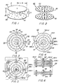
- Figure 3 is a plan view of a wafer 52 used in the cell 63 of Figure 2.
- a first pair of "clearance" slots 54 having sides 55 parallel to and equidistant from a diameter of wafer 52 extends inwardly from diametrically opposed sides of the perimeter 56 of the wafer.
- Each slot 54 has a transverse inner end wall 57, which is preferably concavely shaped.
- a second pair of diametrically opposed "pinch" slots 58 that extend inward from perimeter 56 of the wafer, centered on a diameter rotated ninety degrees from that of slots 54. Slots 58 also have parallel side walls 59 parallel to and equidistant from a diameter of wafer 52.
- pinch slots 58 is less than the width of clearance slots 54. Also, the inner end wall 60 of each slot 58 has an arcuate shape, forming an enlarged truncated circular opening having a larger diameter than the width of the slot.
- Each wafer 52 has through its thickness dimension a central coaxial perforation or hole 61 of larger diameter than perforations 53. The purposes of slots 54 and 58, and central hole 61, are described below.
- Wafers having the described shape may be manufactured by punching from thin sheet stock. This fabrication method leaves burrs, which are preferably removed by reverse plating.
- wafers 52 may be manufactured continuously from aluminum foil by the photoresist and etch method. In either case, wafers 52 are preferably lightly anodized and boiled in water to seal the surfaces.
- Figure 4 shows a pair of wafers 52A and 52B, one of which is rotated 90° with respect to the other, to form a capacitive cell 63.
- 29 more wafers 52 are added for a total of 31. This construction results in 30 cells 63 disposed end-to-end, in a stack 64, as shown in Figure 6.
- the nominal length of stack 64 is 4.6 mm, and its minimum length, 3.85 mm.
- Rotational alignment of wafers 52 in stack 64 is preferably maintained by four conductive spacer rods 66, spaced 90° apart, as shown in Figure 5.
- two wafer stacks 64 are used in each actuator 85; one stack called a "blind” stack 64A and a second stack called a “coupling” stack 64B are connected to an optical module or capsule, as will be described below.
- insulated centering/actuator rod 65 is inserted through center holes 61 in equally spaced alternate odd and even wafers 52A and 52B. In each stack 64, there is a total of 16 odd and 15 even wafers 52A and 52B, respectively. Rod 65 is preferably cut from an extrusion.
- Centering/actuator rod 65 may have a cruciform cross-sectional shape, which provides spaces adjacent the inner annular wall of central perforation 61 in wafers 52 to facilitate flow of dielectric fluid through stack 64.
- a longitudinally disposed hole 67 is provided in centering/ actuator rod 65 to receive a wire for coupling motion of rod 65 to an optical capsule, as will be described in detail below.
- centering/actuator rod 65 is determined by the method of its attachment to the optical capsule.
- rod 65 is fixed to the end cap of blind wafer stack 64A, protrudes through that stack, the electrical connecting and mounting means, and thence through coupling stack 64B, as shown in Figure 11.
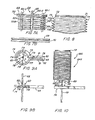
- Figure 5 shows a longitudinally disposed spacer rod 66-4 in the process of being inserted into a longitudinally disposed row of 16 pinch slots 58 in wafers 52. Rods 66-1, 66-2 and 66-3 are shown already mounted.
- Rods 66 are preferably made of a conductive elastomer, such as silicone rubber or other soft and highly compliant elastomer, loaded with carbon black, or other electrically conductive material.
- the material from which rods 66 are made must be sufficiently compliant in a longitudinal direction to compress readily when wafers 52 are elecrostatically attracted to one another.
- Wafer 52A and all other alternate, even numbered wafers, for a total of 16 are mechanically and conductively connected by spacing rods 66-1 and 66-3.
- wafer 52B and all other alternate, odd numbered, wafers, for a total of 15 are mechanically and conductively connected to spacer rods 66-2 and 66-4.
- the radius of spacer rods 66 is slightly larger than the radius of the inner end wall 60 of both pinched radial slots 58 in each wafer 52. This interference fit of rod 66 in slot 58 has the effect of pinching the rubber rod slightly, so that the wafers may not shift in any direction relative to the rods after assembly.
- Figure 7A is a broken side view of a stack 64 of 31 odd numbered wafers 52A-1 through 52A-31, and even numbered wafers 52B-22 through 52B-30. Interleaved between each adjacent pair of wafers 52 is a "sacrificial" spacer washer 68. A total of 30 washers 68 are required. Spacer washers 68 may be punched from a low compliance, open celled, thin, sheet sponge material. If silicone spacer rods are used, then an open-cell acrylic-like foam material may be used.
- the thickness of sacrificial washers 68 is about 200 ⁇ m in the example embodiment.
- each of two end caps 69 (only one is shown), nominally 1.5 mm thick, is bonded to an end wafer at both ends of the stack.
- end cap 69 has a hole pattern identical to the hole pattern in wafers 52 to permit the flow of liquid dielectric through the end cap.
- End cap 69 also has an annular groove 70 around its perimeter for ease in gripping and bonding the collar end of actuator housing 71, as shown in Figure 7B.
- End caps 69 may be strung along the conductive spacer rods 66 before this step, since the spacer rods are assembled by pressing them into radial slots 58 in wafers 52.
- Conductive spacer rods 66 are then bonded to end cap 69 at one end of stack 64. Silicone adhesive or the like is used for this purpose.
- sacrificial spacers 68 may be made substantially thicker than 50 f..lm, say 200 ⁇ m. In this case, the stack is artificially lengthened from the working maximum 4.6 mm to:
- stack 64 While still held in the processing tool, and with centering/actuator rod 65 removed, stack 64 is submerged in an ultrasonic cleaning tank, preferably under a partial vacuum.
- the solvent in the tank may be a ketone, mono- or polyhydric alcohol, or the equivalent. In the case of the materials named for this example, this solventwill rapidly and selectively dissolve the porous acrylic sacrificial washers 68 while leaving wafers 52, silicone spacer rods 66, stack housing 71 and bonding intact.
- a rinse in an ultrasonic tank containing clean water, followed by drying in clean air, is employed to remove any residual solvent.
- "Blind" stack 64A has a centering/actuator rod 65 installed in the stack, and bonded to its end cap 69.
- a "coupling" stack 64B does not have a centering/actuator rod 65 installed during this procedure.
- wafers 52 are nominally spaced 50 ⁇ m apart.
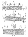
- a housing 71 for stack 64 is shown to comprise a section of thin wall plastic tubing having a collar 72 and a plurality of annular corrugations 73 consisting of alternating longitudinally spaced apart annular ridges and grooves 73A and 73B, respectively, formed in the tubing wall.
- housing 71 has a "relaxed" length corresponding to the minimum actuated length of the wafer stack.
- Housing 71 is slipped over actuator stack 64, and collars 72 of the housing bonded to end caps 69 of the actuator stack. Groove 70 in the periphery of end cap 69 facilitates the bonding process.
- stack 64 includes a connector base 74 provided with a central hole 77 adapted to loosely receive stack aligning, centering/actuator rod 65.
- Base 74 is of generally uniform thickness, and has a disk-shaped portion 75 and a radially outwardly protruding arm or mounting tab 76, giving the base in plan view the shape of a banjo.
- Base 74 is preferably fabricated as a punched printed circuit board, with two sets of holes. One set of holes 78 through base 74 permits the free flow of liquid dielectric through them.
- Each of the four holes 79 is adapted to receive a needle 80, which is in turn adapted to make electrically conductive contact with a rod 66.
- Each pair of diametrically opposed needles 80 is connected via a separate conductive strip 81 on the lower surface of base 74 to a separate metal eyelet 82 on lower surface 83 of mounting tab 76. Eyelets 81 are adapted to connect the wafer stack electrically with flexible leads to remote servo control circuits.
- Needles 80 have heads on one end resembling flat head rivets, the other ends sharpened. They are pressed into plated through-holes 79 of connector base 74.
- Figure 10 shows a stack connector base 74 rotationally and axially aligned with the end cap 69 of a blind wafer stack 64A.
- stack connector base 74 and end cap 69 are pressed together and bonded via any convenient means, such as with an adhesive, the loosely fitting, fluted centering rod 65 passes through wafers 52 of the stack; and the four needles 80 pierce the ends of the four corresponding conductive elastomer rods 66 of the stack.
- Athin insulating sheet 84 is placed between lower surfaces 83 of connector bases 74, and bonded to the bases.
- Centering/actuator rod 65 of blind stack 64A protrudes through both stack 64A and 64B of actuator 85.
- Two stacks 64A and 64B assembled as described comprise an actuator 85.
- Figure 12 shows an actuator 85, the end caps 69A and 69B which are held and clamped at a longitudinal separation of 18.2 mm.
- Elastomer collars 86 and 87 mate with and provide sealing to end cap 69A of blind stack 64A and end cap 69B of coupling stack 64B, respectively.
- Bottom collar and seal 87 is then temporarily connected by a fill tube 88, to a container of liquid dielectric.
- Upper collar and seal 86 is fitted to a length of transparent vacuum tubing 89 and thence to a source of a partial vacuum. Liquid dielectric is then drawn upward by operation of the vacuum source to fill the interior volumes of both stacks 64A and 64B, and rises into transparent vacuum tubing 89.
- vibrating means are used to shake the stacks, to help release any air bubbles which may be trapped within the interior of the stacks.
- blind end cap 69A is filled with liquid dielectric, covered and sealed (bubble free) with a concentrically corrugated elastomer lid 90, as shown in Figure 13.
- actuator 85 is inverted. Collar and seal 87 is then removed, while end caps 69A and 69B are still held at a longitudinally spacing of 18.2 mm. Centering/actuator rod 65 is then bonded to end cap 69B at the location indicated generally by the numeral 91, as shown in Figure 12.
- a concentrically corrugated elastomer lid or diaphragm 92 is used to enclose and seal (bubble free) centering/actuating rod 65 and end cap 69B.
- the corrugations 92A in diaphragm 92 permit the center portion of lid 92 to move axially with respect to the rim of the lid, while maintaining a liquid-tight bond between the annular inner wall 92C of a central coaxial hole 92B provided to receive centering rod 65.
- Figure 13 shows a finished actuator85 of the example pick-up.
- the design and dimensions of centering/actuator rod 65 are determined by the geometry of the pick-up in which the actuators are used.
- cruciform actuator rod 65 is cut short, and a fine coupling wire 93 is fixed in hole 67 that extends axially through the rod.
- one terminal of a voltage source is connected to a pair of diametrically opposed conductive spacer rods, such as 66-1 and 66-3.
- the other terminal of the voltage source is connected to the other pair of diametrically opposed conductive spacer rods, i.e., rods 66-2 and 66-4 in this example.
- This arrangement results in a potential difference existing between each pair of adjacent wafers 52, such as wafers 52A and 52B.
- the attractive force caused by the potential difference causes the even number wafers 52B to move axially relatively towards the odd number wafers 52A, compressing elastic spacer rods 66 attached to the wafers.
- actuator rod 65 moves outward, and may be used to exert a pushing force.
- coupling stack 64B is actuated, that stack is contracted, retracting actuator rod 65, which may be then used to exert a pulling force.
- actuator 85 when actuator 85 is held rigidly by mounting tabs 76A and 76B, actuator rod 65 is free to move longitudinally ⁇ 0.75 mm, plus a margin for tolerances.
- the actuator is dynamically centered dimensionally in its operating range.
- a modification of the novel electrostatic actuator according to the present invention which has a simplified construction having a push-only force actuating capability, rather than push-pull capability of actuator 85 shown in Figure 13 and described above.
- a concentrically corrugated lid or diaphragm 92 of the type shown in Figure 13A and described above may be attached coaxially to lower surface 83 of stack connector base 74 and centering/actuator rod 65, by means of fluid-tight bonds, thus forming an uni-directional force actuator 85-C.
- actuator housing 71 contracts. Therefore, since the inner end of centering/actuator rod 65 is fixed to an upper lid 92 sealed to upper end cap 69A, contraction of housing 71 causes centering/actuator rod 65 to extend outwards from stack connector base 74.
- lid 92 permits centering/actuator rod 65 to move axially with respect to connector base 74, while the outer rim and inner central hole wall of the lid remain in fluid-tight connection with the base and centering rod, respectively.
- spring bias means may be used to retract centering actuator rod 65 when the electrostatic contraction force is removed from upper actuator 85-C.
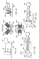
- optical module or capsule 94 of the example embodiment comprises an objective lens 95 or its equivalent, and two or more single-mode optical fibers 96 connected to remote optoelectronic and servo circuits 97.
- optical axis of objective lens 95 which preferably is a molded, aspheric objective lens with a numerical aperture (NA) in a typical range of about 0.5 to 0.6, is normal to the outer surface 98 of video disk 99, and focussed upon the information-bearing surface 100 of the disk.
- NA numerical aperture
- Figure 15A is an end view of one embodiment of a pick-up apparatus 101, according to the present invention, using two low-mass, fast-response actuators 85, positioned relative to a video disk 99, its outer surface 98 and its information bearing surface 100.
- the longitudinal axes of a pair of push-pull actuators 85-1 and 85-2 which coincide with their nominal lines of action, are inclined at equal angles to a perpendicular normal to information bearing surface 100, and lie in a vertical plane perpendicular to information containing tracks on disk 99.
- this arrangement provides a two-axis deflection capability for pick-up apparatus 101, namely in a vertical, focus direction and a radial, tracking direction.
- the orientation of the end view of Figure 15A is of a cross section of the disk and tangential with respect to the spiral information tracks 102 of the disk, as shown in Figure 15B.
- Optics bearing capsule 94 is suspended at a distance from and normal to the surface 100, by bonding means to coupling wires 93 which protrude from centering/actuator rods 65 of actuators 85, and which also provide lateral support.
- the projections of the axes of flexible coupling wires 93 coincide at the center of mass 110 of optical capsule 94.
- coupling wires 93 are, in turn, each coupled coaxially to an actuator 85, through hole 67 in the centering/ actuator rod 65 already provided.
- Actuators 85 are held rigidly by external means at angles of 45° relative to the information bearing surface 100.
- Coupling wires 93 are preferably short segments of fine piano wire, stiff longitudinally but compliant in bending. They may be attached to housing tube 103 of optical capsule 94 by spot welding or other suitable means.
- Figure 16 is an end view of the pick-up apparatus 101 of Figure 15.
- the orientation of the view is of a cross section of a video disk along a radius.
- Mounting tab 76 of the nearer actuator 85-1 of the two actuators, the farther actuator 85-2 being hidden, is held rigidly by external transport means not shown.
- Two pairs of electrical wires 104-1 connect actuator 85-1 to remote servo control electronics 97.
- An identical set of wires 104-2 connects the farther actuator, not shown, to electronics assembly 97.
- the preferred embodiment includes tabs provided on the edges of printed circuit boards, which may be connected to the pick-up mounting means by a simple connector.
- optical fibers 96 extend from optical capsule 94 to remote optoelectronics 97.
- the optical fibers are held straight by a drag link, not shown, which is described below.
- a drag link assembly 105 is used to provide the following functions: (A) Stabilize the position of the optical capsule 94, in the plane parallel to the information bearing surface of a video disk, in the direction tangential to the optical spiral path, or tracks of the disk, (B) Reduce torsional motions in both axes about the centroid of the optical capsule, (C) Support optical coupling fibers 96 in a straight and flat manner from the optical capsule to the remote optoelectronics, and (D) Reduce the effects of the gravitational orientation of the video disk system.
- Drag link 105 is bonded to the optical capsule 94 and torsionally hinged to the appropriate portion 106 of the transport, not shown, preferably by means of a torsional wire 108.
- Drag link 105 is preferably made of a structural, closed cell foam, and is constructed to exactly balance the mass of optical capsule 94, by means of a counterweight 109, with no torque on hinge wire 108. Any residual forces on optical capsule 94, caused by actuators 85, are compensated for by other means.
- the length of drag link 105 between torsional hinge 108 and optical capsule 94 is determined by the angle of tilt of the optical axis of the capsule from the normal which may be tolerated:
- the function of the transport supporting a pick-up apparatus is to convey the low mass, fast response pick- up of the present invention, on a time-integrated, error averaging basis.
- the low mass of the novel pick-up apparatus according to the present invention reduces the stress on the transport during perturbations. Therefore, the transport may be smaller and lighter than those presently used. For example, a transport made primarily of structural foam materials, instead of heavier materials, may be usable with the novel pick-up according to the present invention.
- each actuator 85 of pick-up apparatus 101 provides continuously controlled travel through its centering/actuator rod 65 linked by compliant wire 93 to the center of mass 110 of optical capsule 94 of 1.5 mm peak-to-peak amplitude.
- the axis CD represents the limits of tracking correction attainable with pick-up apparatus 101.
- circle 111 of diameter D 1.5 mm, equivalent to more than 900 tracks, defines the limit of any combination of focus and tracking corrections achievable with the example embodiment or pick-up apparatus 101.
- a tracking maintenance range of 900 tracks represents one-half minute of playing time; for a rotation rate of 80 RPM, the maintenance time would be approximately 11 minutes.
- the center 112 of the 1.5 mm-diameter circular performance envelope 111 lies on the information bearing surface 100 of the video disk 99.
- center 112 is maintained at the correct point on surface 100 for focusing and tracking.
- very low control voltages on actuators 85 of pick-up apparatus 101 are required to maintain the desired position of tracking point 112, since the accelerations are relatively small.
- the performance envelope or pick-up apparatus 101 will not be exceeded. Then, because of the extremely low relative mass of the pick-up, the focal point, determined by the servo controlled pick-up will maintain continuous focusing and tracking of information bearing tracks on the video disk.
- the pick-up apparatus 101 compensates for shocks in the radial or x axis and in the normal or z axis, corresponding to tracking and focusing, respectively. If, in addition, shock compensation in the tangential or y axis is to be incorporated in the pick-up, one method is to place within the drag link 105 a third actuator having a line of action parallel to the longitudinal axis of the drag link, as shown in Figure 17B. Preferably, however, a modified embodiment 121 of the present invention, shown in Figures 21-23 would be used to achieve a three-axis deflection capability.
- three-axis pick-up apparatus 121 includes three transducers 122-A, 122-B and 122-C held rigidly 120° apart by a transport (not shown) and connected together centrally to an optical capsule 122 by means of stiff wiresl 24A, 124B, and 124C.
- each transducer 122 is held rigidly by its mounting tab 76, bonded to an arm 125 of a transport mechanism, not shown, at an angle of 45° with respect to the information-bearing layer of the video disk 119.
- the shock compensation illustrated by Figure 20B as a circular plane normal to and centered on the information bearing layer of the video disk is converted to shock compensation envelope described by a sphere identically located.
- Time base errors arising from perturbations in the rotational speed of a video disk, may be corrected along the y axis during normal play be means of the three-axis pick-up.
- novel actuator configurations used in pick-up apparatus 101 and pick-up apparatus 121, described above could use other types of electrostrictive or magnetostrictive linear actuators.
Landscapes
- Optical Recording Or Reproduction (AREA)
- Micromachines (AREA)
Priority Applications (1)
| Application Number | Priority Date | Filing Date | Title |
|---|---|---|---|
| EP97116241A EP0825593B1 (fr) | 1993-02-05 | 1994-02-02 | Tête actionnée électrostatiquement et résistante aux chocs pour l'enregistrement et lecture optique |
Applications Claiming Priority (2)
| Application Number | Priority Date | Filing Date | Title |
|---|---|---|---|
| US13773 | 1993-02-05 | ||
| US08/013,773 US5485437A (en) | 1993-02-05 | 1993-02-05 | Shock-resistant, electrostatically actuated pick-up for optical recording and playback |
Related Child Applications (1)
| Application Number | Title | Priority Date | Filing Date |
|---|---|---|---|
| EP97116241A Division EP0825593B1 (fr) | 1993-02-05 | 1994-02-02 | Tête actionnée électrostatiquement et résistante aux chocs pour l'enregistrement et lecture optique |
Publications (3)
| Publication Number | Publication Date |
|---|---|
| EP0613124A2 true EP0613124A2 (fr) | 1994-08-31 |
| EP0613124A3 EP0613124A3 (fr) | 1995-01-04 |
| EP0613124B1 EP0613124B1 (fr) | 1999-04-28 |
Family
ID=21761681
Family Applications (2)
| Application Number | Title | Priority Date | Filing Date |
|---|---|---|---|
| EP97116241A Expired - Lifetime EP0825593B1 (fr) | 1993-02-05 | 1994-02-02 | Tête actionnée électrostatiquement et résistante aux chocs pour l'enregistrement et lecture optique |
| EP94300766A Expired - Lifetime EP0613124B1 (fr) | 1993-02-05 | 1994-02-02 | Actionneur linéaire, en particulier pour tête optique |
Family Applications Before (1)
| Application Number | Title | Priority Date | Filing Date |
|---|---|---|---|
| EP97116241A Expired - Lifetime EP0825593B1 (fr) | 1993-02-05 | 1994-02-02 | Tête actionnée électrostatiquement et résistante aux chocs pour l'enregistrement et lecture optique |
Country Status (4)
| Country | Link |
|---|---|
| US (2) | US5485437A (fr) |
| EP (2) | EP0825593B1 (fr) |
| JP (1) | JP2719109B2 (fr) |
| DE (2) | DE69427310T2 (fr) |
Cited By (7)
| Publication number | Priority date | Publication date | Assignee | Title |
|---|---|---|---|---|
| EP0798705A3 (fr) * | 1996-03-28 | 1999-03-24 | Kabushiki Kaisha Toshiba | Appareil d'entraínement pour une lentille d'objectif |
| EP0991175A1 (fr) * | 1998-09-30 | 2000-04-05 | STMicroelectronics S.r.l. | Microactionneur intégré à haute performance en particulier pour un transducteur de lecture/écriture dans une unité à disque |
| US6198145B1 (en) | 1997-10-29 | 2001-03-06 | Stmicroelectronics, S.R.L. | Method for manufacturing a semiconductor material integrated microactuator, in particular for a hard disc mobile read/write head, and a microactuator obtained thereby |
| US6446326B1 (en) | 1998-05-05 | 2002-09-10 | Stmicroelectronics S.R.L. | Method for manufacturing a hard disk read/write unit, with micrometric actuation |
| US6496997B1 (en) | 1998-07-22 | 2002-12-24 | St Microelectronics Srl | Hard disk driver with an integrated structure for electrostatically removing dielectric particles generated during the operation, and electrostatic cleaning method for a hard disk driver |
| US6501623B1 (en) | 1998-07-30 | 2002-12-31 | Stmicroelectronics S.R.L. | Method for assembling an actuator device for a hard disk, comprising a read/write transducer, a microactuator, and a suspension, and the actuator device thus obtained |
| US6809907B1 (en) | 1998-07-30 | 2004-10-26 | Stmicroelectronics S.R.L | Remote-operated integrated microactuator, in particular for a read/write transducer of hard disks |
Families Citing this family (12)
| Publication number | Priority date | Publication date | Assignee | Title |
|---|---|---|---|---|
| US5729511A (en) | 1991-02-15 | 1998-03-17 | Discovision Associates | Optical disc system having servo motor and servo error detection assembly operated relative to monitored quad sum signal |
| US5642015A (en) * | 1993-07-14 | 1997-06-24 | The University Of British Columbia | Elastomeric micro electro mechanical systems |
| US5682075A (en) * | 1993-07-14 | 1997-10-28 | The University Of British Columbia | Porous gas reservoir electrostatic transducer |
| AU5707796A (en) * | 1996-03-26 | 1997-10-17 | Mats Bexell | An actuator motor and a method for fabrication of such an actuator |
| DE19715488C1 (de) * | 1997-04-14 | 1998-06-25 | Siemens Ag | Piezoaktor mit neuer Kontaktierung und Herstellverfahren |
| EP0908961B1 (fr) * | 1997-10-13 | 2003-06-04 | Sagem S.A. | Actionneur amplifié à matériaux actifs |
| DE19802302A1 (de) * | 1998-01-22 | 1999-07-29 | Bosch Gmbh Robert | Piezoelektrischer Aktor |
| US6512323B2 (en) | 2000-03-22 | 2003-01-28 | Caterpillar Inc. | Piezoelectric actuator device |
| US6930487B2 (en) * | 2002-12-12 | 2005-08-16 | Howard L. North, Jr. | Method for electronic damping of electrostatic positioners |
| US20040140733A1 (en) * | 2003-01-13 | 2004-07-22 | Keller Christopher Guild | Electrostatic actuator with a multiplicity of stacked parallel plates |
| US7623142B2 (en) * | 2004-09-14 | 2009-11-24 | Hewlett-Packard Development Company, L.P. | Flexure |
| JP2021112096A (ja) * | 2020-01-15 | 2021-08-02 | 株式会社デンソー | アクチュエータおよびアクチュエータシステム |
Family Cites Families (40)
| Publication number | Priority date | Publication date | Assignee | Title |
|---|---|---|---|---|
| US2113184A (en) * | 1934-11-23 | 1938-04-05 | Sperti George | Method of recording and reproducing sound on film |
| US2975307A (en) * | 1958-01-02 | 1961-03-14 | Ibm | Capacitive prime mover |
| DE1167550B (de) * | 1959-01-09 | 1964-04-09 | Columbia Broadcasting Syst Inc | Piezoelektrischer Tonabnehmer |
| US3530258A (en) * | 1968-06-28 | 1970-09-22 | Mca Technology Inc | Video signal transducer having servo controlled flexible fiber optic track centering |
| DE2661053C2 (fr) * | 1975-10-08 | 1988-05-26 | Olympus Optical Co., Ltd., Tokio/Tokyo, Jp | |
| US4302830A (en) * | 1978-05-10 | 1981-11-24 | Olympus Optical Company Ltd. | Optical information reading-out apparatus |
| JPS5593544A (en) * | 1979-01-09 | 1980-07-16 | Sony Corp | Multi-axis movable mirror unit |
| NL7904618A (nl) * | 1979-06-13 | 1980-12-16 | Philips Nv | Optische focusseerinrichting. |
| GB2060927B (en) * | 1979-07-24 | 1984-02-01 | Universal Pioneer Corp | Signal reading device for optical discs |
| US4322837A (en) * | 1979-08-27 | 1982-03-30 | Discovision Associates | Dithered center tracking system |
| US4342935A (en) * | 1980-04-10 | 1982-08-03 | Discovision Associates | Binary piezoelectric drive for lens focusing system |
| CA1132258A (fr) * | 1980-05-12 | 1982-09-21 | Herman W. Willemsen | Tete d'exploration pour systeme optique a disques |
| JPS57205834A (en) * | 1981-06-12 | 1982-12-17 | Matsushita Electric Ind Co Ltd | Light focusing position controller |
| US4488789A (en) * | 1981-12-21 | 1984-12-18 | North American Philips Corporation | Electromagnetically deflectable device |
| JPH065585B2 (ja) * | 1984-02-15 | 1994-01-19 | 株式会社日立製作所 | 光磁気記憶装置 |
| JPS60239943A (ja) * | 1984-05-15 | 1985-11-28 | Matsushita Electric Ind Co Ltd | 光学ヘツド |
| EP0228620B1 (fr) * | 1985-12-10 | 1991-06-05 | Nec Corporation | Tête optique avec réseau de diffraction pour diriger deux ou plusieurs faisceaux lumineux diffractés sur des détecteurs optiques |
| KR900003521B1 (ko) * | 1986-02-28 | 1990-05-21 | 삼성전자 주식회사 | 광테이프 기록재생용 레이저 드럼 |
| DE3789099T2 (de) * | 1986-12-26 | 1994-07-14 | Toshiba Kawasaki Kk | Steuerungsgerät für Objektivlinse. |
| JPS63195834A (ja) * | 1987-02-10 | 1988-08-12 | Pioneer Electronic Corp | 可動体支持装置 |
| JP2637415B2 (ja) * | 1987-03-03 | 1997-08-06 | オリンパス光学工業株式会社 | 光磁気記録再生装置 |
| JPS63220432A (ja) * | 1987-03-10 | 1988-09-13 | Toshiba Corp | 光学ヘツド |
| JPS63257927A (ja) * | 1987-04-15 | 1988-10-25 | Pioneer Electronic Corp | ピツクアツプアクチユエ−タ |
| US4794581A (en) * | 1987-06-25 | 1988-12-27 | International Business Machines Corporation | Lens support system enabling focussing and tracking motions employing a unitary lens holder |
| JPS6419926A (en) * | 1987-07-14 | 1989-01-24 | Hitachi Metals Ltd | Switching power source |
| US4945527A (en) * | 1987-09-30 | 1990-07-31 | Fuji Photo Film Co., Ltd. | Optical pickup apparatus for detection of focusing error, tracking error, and information |
| JPH01119926A (ja) * | 1987-11-02 | 1989-05-12 | Mitsubishi Electric Corp | 対物レンズ駆動装置 |
| EP0319038B1 (fr) * | 1987-12-02 | 1994-07-13 | Nec Corporation | Structure pour sceller un élément électrostrictif |
| JP2647113B2 (ja) * | 1988-01-21 | 1997-08-27 | 株式会社東芝 | 静電アクチュエータ |
| JPH01238470A (ja) * | 1988-03-18 | 1989-09-22 | Hitachi Ltd | 直接駆動装置 |
| US4945526A (en) * | 1988-10-18 | 1990-07-31 | Laser Magnetic Storage International Company | Actuator assembly for optical disk systems |
| US5113108A (en) * | 1988-11-04 | 1992-05-12 | Nec Corporation | Hermetically sealed electrostrictive actuator |
| JP2937348B2 (ja) * | 1989-07-20 | 1999-08-23 | 日本電気株式会社 | 位置決め装置 |
| JPH03132082A (ja) * | 1989-10-18 | 1991-06-05 | Hitachi Ltd | 多軸マニピュレーター |
| US5084645A (en) * | 1989-11-30 | 1992-01-28 | The United States Of America As Represented By The Administrator Of The National Aeronautics And Space Administration | Electrorepulsive actuator |
| US5170089A (en) * | 1989-12-20 | 1992-12-08 | General Electric Company | Two-axis motion apparatus utilizing piezoelectric material |
| JPH04162229A (ja) * | 1990-10-26 | 1992-06-05 | Canon Inc | プローブ装置 |
| US5206557A (en) * | 1990-11-27 | 1993-04-27 | Mcnc | Microelectromechanical transducer and fabrication method |
| JPH04340373A (ja) * | 1991-05-14 | 1992-11-26 | Nippon Ceramic Co Ltd | 圧電素子利用の移動機構 |
| US5179499A (en) * | 1992-04-14 | 1993-01-12 | Cornell Research Foundation, Inc. | Multi-dimensional precision micro-actuator |
-
1993
- 1993-02-05 US US08/013,773 patent/US5485437A/en not_active Expired - Lifetime
-
1994
- 1994-02-02 EP EP97116241A patent/EP0825593B1/fr not_active Expired - Lifetime
- 1994-02-02 EP EP94300766A patent/EP0613124B1/fr not_active Expired - Lifetime
- 1994-02-02 DE DE69427310T patent/DE69427310T2/de not_active Expired - Lifetime
- 1994-02-02 DE DE69418079T patent/DE69418079T2/de not_active Expired - Lifetime
- 1994-02-07 JP JP6013676A patent/JP2719109B2/ja not_active Expired - Fee Related
- 1994-11-01 US US08/333,107 patent/US5521452A/en not_active Expired - Lifetime
Cited By (9)
| Publication number | Priority date | Publication date | Assignee | Title |
|---|---|---|---|---|
| EP0798705A3 (fr) * | 1996-03-28 | 1999-03-24 | Kabushiki Kaisha Toshiba | Appareil d'entraínement pour une lentille d'objectif |
| US6198145B1 (en) | 1997-10-29 | 2001-03-06 | Stmicroelectronics, S.R.L. | Method for manufacturing a semiconductor material integrated microactuator, in particular for a hard disc mobile read/write head, and a microactuator obtained thereby |
| US6458616B2 (en) | 1997-10-29 | 2002-10-01 | Stmicroelectronics S.R.L. | Method for manufacturing a semiconductor material integrated microactuator, in particular for a hard disc mobile read/write head, and a microactuator obtained thereby |
| US6446326B1 (en) | 1998-05-05 | 2002-09-10 | Stmicroelectronics S.R.L. | Method for manufacturing a hard disk read/write unit, with micrometric actuation |
| US6496997B1 (en) | 1998-07-22 | 2002-12-24 | St Microelectronics Srl | Hard disk driver with an integrated structure for electrostatically removing dielectric particles generated during the operation, and electrostatic cleaning method for a hard disk driver |
| US6501623B1 (en) | 1998-07-30 | 2002-12-31 | Stmicroelectronics S.R.L. | Method for assembling an actuator device for a hard disk, comprising a read/write transducer, a microactuator, and a suspension, and the actuator device thus obtained |
| US6809907B1 (en) | 1998-07-30 | 2004-10-26 | Stmicroelectronics S.R.L | Remote-operated integrated microactuator, in particular for a read/write transducer of hard disks |
| EP0991175A1 (fr) * | 1998-09-30 | 2000-04-05 | STMicroelectronics S.r.l. | Microactionneur intégré à haute performance en particulier pour un transducteur de lecture/écriture dans une unité à disque |
| US6404599B1 (en) | 1998-09-30 | 2002-06-11 | Stmicroelectronics, S.R.L. | High-performance integrated microactuator, particularly for a hard disk read/write transducer |
Also Published As
| Publication number | Publication date |
|---|---|
| EP0825593A1 (fr) | 1998-02-25 |
| DE69427310D1 (de) | 2001-06-28 |
| US5521452A (en) | 1996-05-28 |
| JP2719109B2 (ja) | 1998-02-25 |
| US5485437A (en) | 1996-01-16 |
| DE69418079D1 (de) | 1999-06-02 |
| EP0613124A3 (fr) | 1995-01-04 |
| EP0613124B1 (fr) | 1999-04-28 |
| DE69418079T2 (de) | 1999-08-19 |
| JPH06343277A (ja) | 1994-12-13 |
| EP0825593B1 (fr) | 2001-05-23 |
| DE69427310T2 (de) | 2001-10-11 |
Similar Documents
| Publication | Publication Date | Title |
|---|---|---|
| US5521452A (en) | Shock-resistant, electrostatically actuated pick-up for optical recording and playback | |
| EP0137283B1 (fr) | Dispositif de tête optique | |
| US4472024A (en) | Apparatus for driving objective lens | |
| Fan et al. | Electrostatic microactuator and design considerations for HDD applications | |
| US5933405A (en) | Sliding actuator of a digital versatile disc player capable of smoothly moving an object lens | |
| KR950010329B1 (ko) | 정보기록재생장치의 광학부 구동장치 | |
| JPS63224039A (ja) | 対物レンズ駆動装置 | |
| JPS61258346A (ja) | 光ピツクアツプの対物レンズ支持装置 | |
| JPH04319537A (ja) | 対物レンズ駆動装置 | |
| US7933174B2 (en) | Optical pickup with support part having hole for being inserted with a projection part of a case | |
| JPS58222449A (ja) | 光デイスク用アクチユエ−タ | |
| KR100430063B1 (ko) | 정보저장기기용 미세구동기 | |
| JPH05314511A (ja) | 対物レンズ駆動装置 | |
| KR100526347B1 (ko) | 광픽업 구동기 | |
| JPH06124467A (ja) | 対物レンズ駆動装置 | |
| KR100504776B1 (ko) | 광자기 기록/재생용 마이크로 광자기 헤드 및 그 제조방법 | |
| JPS6185639A (ja) | 光学ヘツド装置 | |
| JP2602855B2 (ja) | 対物レンズ駆動装置 | |
| JPS61115248A (ja) | 光情報読取り装置における対物レンズ支持装置 | |
| JPS6063739A (ja) | 対物レンズの2次元駆動装置 | |
| JPS60246032A (ja) | 対物レンズ駆動装置 | |
| JPH01100742A (ja) | 対物レンズ駆動装置 | |
| JPH011132A (ja) | 対物レンズ駆動装置 | |
| JPH0121541B2 (fr) | ||
| JPH056755B2 (fr) |
Legal Events
| Date | Code | Title | Description |
|---|---|---|---|
| PUAI | Public reference made under article 153(3) epc to a published international application that has entered the european phase |
Free format text: ORIGINAL CODE: 0009012 |
|
| AK | Designated contracting states |
Kind code of ref document: A2 Designated state(s): DE FR GB IT NL |
|
| RIN1 | Information on inventor provided before grant (corrected) |
Inventor name: GREGG, DAVID PAUL |
|
| PUAL | Search report despatched |
Free format text: ORIGINAL CODE: 0009013 |
|
| AK | Designated contracting states |
Kind code of ref document: A3 Designated state(s): DE FR GB IT NL |
|
| 17P | Request for examination filed |
Effective date: 19950426 |
|
| 17Q | First examination report despatched |
Effective date: 19970604 |
|
| GRAG | Despatch of communication of intention to grant |
Free format text: ORIGINAL CODE: EPIDOS AGRA |
|
| GRAG | Despatch of communication of intention to grant |
Free format text: ORIGINAL CODE: EPIDOS AGRA |
|
| GRAH | Despatch of communication of intention to grant a patent |
Free format text: ORIGINAL CODE: EPIDOS IGRA |
|
| GRAH | Despatch of communication of intention to grant a patent |
Free format text: ORIGINAL CODE: EPIDOS IGRA |
|
| GRAA | (expected) grant |
Free format text: ORIGINAL CODE: 0009210 |
|
| AK | Designated contracting states |
Kind code of ref document: B1 Designated state(s): DE FR GB IT NL |
|
| DX | Miscellaneous (deleted) | ||
| REF | Corresponds to: |
Ref document number: 69418079 Country of ref document: DE Date of ref document: 19990602 |
|
| ET | Fr: translation filed | ||
| PLBE | No opposition filed within time limit |
Free format text: ORIGINAL CODE: 0009261 |
|
| STAA | Information on the status of an ep patent application or granted ep patent |
Free format text: STATUS: NO OPPOSITION FILED WITHIN TIME LIMIT |
|
| 26N | No opposition filed | ||
| REG | Reference to a national code |
Ref country code: GB Ref legal event code: IF02 |
|
| PGFP | Annual fee paid to national office [announced via postgrant information from national office to epo] |
Ref country code: IT Payment date: 20120224 Year of fee payment: 19 |
|
| PGFP | Annual fee paid to national office [announced via postgrant information from national office to epo] |
Ref country code: GB Payment date: 20130227 Year of fee payment: 20 Ref country code: FR Payment date: 20130311 Year of fee payment: 20 Ref country code: DE Payment date: 20130227 Year of fee payment: 20 |
|
| PGFP | Annual fee paid to national office [announced via postgrant information from national office to epo] |
Ref country code: NL Payment date: 20130224 Year of fee payment: 20 |
|
| REG | Reference to a national code |
Ref country code: DE Ref legal event code: R071 Ref document number: 69418079 Country of ref document: DE |
|
| REG | Reference to a national code |
Ref country code: NL Ref legal event code: V4 Effective date: 20140202 |
|
| REG | Reference to a national code |
Ref country code: GB Ref legal event code: PE20 Expiry date: 20140201 |
|
| PG25 | Lapsed in a contracting state [announced via postgrant information from national office to epo] |
Ref country code: DE Free format text: LAPSE BECAUSE OF EXPIRATION OF PROTECTION Effective date: 20140204 Ref country code: GB Free format text: LAPSE BECAUSE OF EXPIRATION OF PROTECTION Effective date: 20140201 |