EP0629363B1 - Butée d'extrémité inférieure séparable pour fermeture à glissière du type masque - Google Patents
Butée d'extrémité inférieure séparable pour fermeture à glissière du type masque Download PDFInfo
- Publication number
- EP0629363B1 EP0629363B1 EP94108033A EP94108033A EP0629363B1 EP 0629363 B1 EP0629363 B1 EP 0629363B1 EP 94108033 A EP94108033 A EP 94108033A EP 94108033 A EP94108033 A EP 94108033A EP 0629363 B1 EP0629363 B1 EP 0629363B1
- Authority
- EP
- European Patent Office
- Prior art keywords
- box
- pin
- separable
- slider body
- stringers
- Prior art date
- Legal status (The legal status is an assumption and is not a legal conclusion. Google has not performed a legal analysis and makes no representation as to the accuracy of the status listed.)
- Expired - Lifetime
Links
Images
Classifications
-
- A—HUMAN NECESSITIES
- A44—HABERDASHERY; JEWELLERY
- A44B—BUTTONS, PINS, BUCKLES, SLIDE FASTENERS, OR THE LIKE
- A44B19/00—Slide fasteners
- A44B19/24—Details
- A44B19/36—Means for permanently uniting the stringers at the end; Means for stopping movement of slider at the end
-
- A—HUMAN NECESSITIES
- A44—HABERDASHERY; JEWELLERY
- A44B—BUTTONS, PINS, BUCKLES, SLIDE FASTENERS, OR THE LIKE
- A44B19/00—Slide fasteners
- A44B19/24—Details
- A44B19/38—Means at the end of stringer by which the slider can be freed from one stringer, e.g. stringers can be completely separated from each other
-
- Y—GENERAL TAGGING OF NEW TECHNOLOGICAL DEVELOPMENTS; GENERAL TAGGING OF CROSS-SECTIONAL TECHNOLOGIES SPANNING OVER SEVERAL SECTIONS OF THE IPC; TECHNICAL SUBJECTS COVERED BY FORMER USPC CROSS-REFERENCE ART COLLECTIONS [XRACs] AND DIGESTS
- Y10—TECHNICAL SUBJECTS COVERED BY FORMER USPC
- Y10T—TECHNICAL SUBJECTS COVERED BY FORMER US CLASSIFICATION
- Y10T24/00—Buckles, buttons, clasps, etc.
- Y10T24/25—Zipper or required component thereof
- Y10T24/2514—Zipper or required component thereof with distinct member for sealing surfaces
-
- Y—GENERAL TAGGING OF NEW TECHNOLOGICAL DEVELOPMENTS; GENERAL TAGGING OF CROSS-SECTIONAL TECHNOLOGIES SPANNING OVER SEVERAL SECTIONS OF THE IPC; TECHNICAL SUBJECTS COVERED BY FORMER USPC CROSS-REFERENCE ART COLLECTIONS [XRACs] AND DIGESTS
- Y10—TECHNICAL SUBJECTS COVERED BY FORMER USPC
- Y10T—TECHNICAL SUBJECTS COVERED BY FORMER US CLASSIFICATION
- Y10T24/00—Buckles, buttons, clasps, etc.
- Y10T24/25—Zipper or required component thereof
- Y10T24/2593—Zipper or required component thereof including complementary, aligning means attached to ends of interlocking surfaces
-
- Y—GENERAL TAGGING OF NEW TECHNOLOGICAL DEVELOPMENTS; GENERAL TAGGING OF CROSS-SECTIONAL TECHNOLOGIES SPANNING OVER SEVERAL SECTIONS OF THE IPC; TECHNICAL SUBJECTS COVERED BY FORMER USPC CROSS-REFERENCE ART COLLECTIONS [XRACs] AND DIGESTS
- Y10—TECHNICAL SUBJECTS COVERED BY FORMER USPC
- Y10T—TECHNICAL SUBJECTS COVERED BY FORMER US CLASSIFICATION
- Y10T24/00—Buckles, buttons, clasps, etc.
- Y10T24/25—Zipper or required component thereof
- Y10T24/2593—Zipper or required component thereof including complementary, aligning means attached to ends of interlocking surfaces
- Y10T24/2595—Zipper or required component thereof including complementary, aligning means attached to ends of interlocking surfaces having specific mounting connection or reinforcing structure at connection
Definitions
- the present invention relates to a separable end stop attached to one end of a fastener chain of a concealed slide fastener so as to permit complete disengagement and then reengagement of two stringers while preventing a slider from leaving the fastener chain.
- the disclosed separable end stop includes a box having at its upper end a recessed step in which a lower end portion of a slider body is received except a front side thereof.
- a front or obverse side of the box is shaped such that right and left front wall portions of the box come into contact with two opposed guide flanges of the slider body.
- FIG. 51-4816 Another known separable end stop for concealed slide fasteners is disclosed in Japanese Utility Model Publication No. 51-4816, which includes a box and a box pin integrally formed such that the box pin and an upper end portion of the peripheral wall of the box jointly form an L-shaped groove in which a lower end portion of a slider body is received except a front side and one lateral side thereof.
- the known separable end stops are unsatisfactory in that when the slider body is brought into abutment with the box, the box receives only a part of the entire periphery of the lower end portion of the slider body.
- the slider body thus received tends to wobble when a separable pin of the separable end stop is inserted into, or removed from the box through the slider body to engage or disengage the two stringers.
- smooth engaging and disengaging operation of the separable end stop can not be achieved.
- the slider body and the box are likely to separate from one another during the engaging and disengaging operation of the separable end stop, This separation not only hinders smooth engaging and disengaging operation of the separable end stop but also causes an accidental chain rupture or separation.
- the box and the box pin are already mounted in an assembled or unitary form on one stringer before the stringer is attached by sewing to an article such as a garment or the like, the box is likely to constitute an obstacle during the sewing operation.
- a separable end stop for concealed slide fasteners which includes a box having structural features that insure stable holding of the lower end portion of a slider body in a box to guarantee smooth engaging and disengaging operation of the separable end stop without causing accidental chain rupture or separation from the separable end stop, and enable a smooth sewing operation without interference with the box when one stringer is sewn to an article.
- the present invention provides a separable end stop for a concealed slide fastener, which is composed of a box, a box pin and a separable pin, wherein the box has a guide slot extending in a front wall of the box for receiving and guiding folded portions of two stringers, and a retaining recess formed at an upper open end of the box for receiving the whole of a lower end portion of a slider body in such a manner that right and left front wall portions extending on opposite sides of the front wall overlap the corresponding wings of the slider body.
- each of the right and left front wall portions has an upper end extension projecting from the open upper end of the box to ensure that the wings of the slider body are overlapped with the front wall portions of the box.
- the box preferably includes a locking portion formed on an interior surface facing a box-pin insertion hole which is separated by a partition wall from a separable-pin insertion hole.
- the box pin has a first locking portion on one side thereof and a second locking portion on an opposite side thereof. The first and second locking portions of the box pin are interlockingly engageable with the locking portion and the partition wall of the box to couple the box and the box pin in an assembled condition.
- a separable end stop is attached to one end (bottom end) of a fastener chain of a concealed slide fastener so as to permit complete disengagement and then reengagement of two stringers 7, 7 while preventing a slider body 12 from leaving the fastener chain.
- Each of the stringers 7, 7 includes a stringer tape 20 carrying on its inner longitudinal edge a row of coupling elements 21.
- the two stringers 7, 7 with the two engaged coupling element rows 21 form the fastener chain.
- the slider body 12 is movable along the coupling element rows 21 to engage and disengage the latter.
- the slider body 12 comprises a flanged base plate 12a and a pair of transversely spaced, elongated front wings 17, 17 extending inwardly from free ends of a pair of guide flanges 12b, 12b extending along opposite sides of the base plate 12a.
- the base plate 12a has a diamond 12c at a fore end thereof, there being defined between the base plate 12a and the front wings 17, 17 a Y-shaped guide channel 12d (FIG.
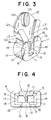
- the front wings 17, 17 are transversely spaced by a longitudinal slot 17a (FIG. 3) communicating with the Y-shaped guide channel 12d.
- the slot 17a receives and guides folded portions of the stringer tapes 20, 20.
- the separable end stop is composed of three components, namely a box 1, a box pin 2 and a separable pin 3.
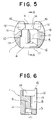
- the box 1 has a hollow structure and is open at an upper end 1a (FIG. 5).
- the box 1 includes a front wall 1b and a rear wall 1c (FIGS. 4 and 6) spaced from each other and interconnected by a pair of sidewalls 1d, 1d spaced from each other.
- the box 1 further has a pair of parallel spaced holes 4 and 5 extending from the open upper end 1a toward a lower end of the box 1 and transversely spaced by a partition wall 6 disposed centrally on an interior surface of the rear wall 1c.
- the hole 4 is shaped to fit the box pin 2, while the hole 5 is shaped to releasably receive the separable pin 3.
- the hole 4 is a through-hole extending across the box 1.
- An interior surface 9 of the sidewall 1d which defines one side of the hole 4 is partly offset to form a step-like locking portion 10 facing toward the lower end of the box 1 for a purpose described below.
- the step-like locking portion 10 on the sidewall 1d separates the hole 4 into an upper portion and a lower portion which is larger in width than the upper portion.
- a bottom wall 11 of the box 1 forms a bottom face of the hole 5.
- the front wall 1b of the box 1 has a guide slot 8 formed to confront the partition wall 6 and extending from the open upper end 1a toward the lower end of the box 1 for receiving and guiding the folded portions of the respective stringer tapes 20, 20.
- the guide slot 8 terminates short of the lower end of the box 1 and communicates with both of the first and second holes 4, 5.
- the front wall 1b is separated into right and left front wall portions 1b', 1b' spaced by the guide slot 8.
- the box 1 has a retaining recess 14 formed at the open upper end 1a thereof for receiving therein the whole of a lower end portion 13 of the slider body 12.
- the retaining recess 14 is shaped to fit the entire periphery of the lower end portion 13 of the slider body 12.
- the box pin 2 is composed of a tubular elongate member of a generally U-shaped cross section and attached to one stringer tape 20 at one end (bottom end) thereof, with a inner longitudinal edge of the stringer tape 20 received in a U-shaped groove in the box pin 2.
- the front end of the box pin 2 has a solid structure.
- the box pin 2 includes a first locking claw 18 formed on an outer sidewall of the box pin 2 at an intermediate portion thereof, and a second locking claw 19 formed on the inner sidewall of the box pin 2 adjacent the front end thereof.
- the first and second locking claw 18, 19 form first and second locking portions, respectively.
- the separable pin 3 is composed of a tubular elongate member of a generally U-shaped cross section and attached to the other stringer tape 20 at one end (bottom end) thereof, with the inner longitudinal edge of the stringer tape 20 received in a U-shaped groove in the separable pin 3.
- the separable pin 3 is insertable into, and removed from the hole 5 in the box 1.
- the separable end stop of the foregoing construction is assembled in a manner described below.
- the box 1 and the box pin 2 are initially formed separately from one another, and in the initial condition (preassembling condition), the partition wall 6 of the box 1 is slightly tilted toward the second hole side, as shown in FIG. 4.
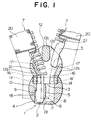
- one stringer 7 including the box pin 2 is attached by sewing to one longitudinal edge of an article such as a garment (not shown). Then, the stringer tape 20 of the stringer 7 is folded over itself along the inner longitudinal edge, and after that while keeping the folded condition of the stringer tape 20, the box pin 2 is inserted from the open upper end 1a of the box 1 into the hole 4. During that time, a folded portion of the stringer tape 20 is received in the guide slot 8 defined between the opposite front wall portions 1b', 1b' of the box 1. The box pin 2 is further inserted into the box 1 until the first locking claw 18 of the box pin 2 is interlocked with the lower end of the step-like locking portion 10 of the box 1, as shown in FIG. 1.
- the partition wall 6, slightly tilted toward the second hole side, is raised up to an upstanding position with the result that the lower end of the partition wall 6 is interlocked with the second locking claw 19.
- the partition wall 6 which is initially slightly tilted toward the second hole side is raised up to an upstanding position when the box pin 2 is inserted into the first hole 4 and reaches a position that the box pin 2 interlocks with the locking portion 10 and the partition wall 6.
- the box 1 and the box pin 2 are firmly connected together.
- a complete stringer 7 which is equipped with the box and and box-pin assembly and the slider body 12 (FIG. 1) is produced.
- the other stringer 7 including the separable pin 3 is also attached by sewing to the opposite longitudinal edge of the article.
- the stringer tape 20 of that stringer 7 is also folded over itself along the inner longitudinal edge thereof.
- the slider body 12 on one stringer 7 is moved in a backward direction (opening direction) along the row of coupling elements 21 toward the box 1.
- the lower end portion 13 of the slider body 12 is completely received in the retaining recess 14 in the box 1, with the front wings 17 of the slider body 12 overlapped with the front wall portions 1b' of the box 1 including their upper end extensions 16.
- the separable pin 3 passes through the slider body 12 and then is inserted into the hole 5 in the box 1.
- the separable end stop thus assembled holds or retains the two stringers 7, 7 in alignment for interlocking.
- the folded portion of the stringers 7, 7 are guidedly received in the guide slot 8 in the box 1 and also in the slot 17a in the slider body 12. Thereafter, the slider body 12 is moved in a forward direction (closing direction) away from the box 1 to engage the rows of coupling elements 21 of the stringers 7, 7, thereby closing the concealed slide fastener.
- the slider body 12 When the concealed slide fastener is to be opened, the slider body 12 is moved in the opening direction toward the box 1 to separate or disengage the rows of coupling elements 21 on the stringers 7, 7.
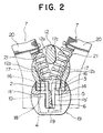
- the slider body 12 When the slider body 12 is brought into abutment with the box 1, the lower end portion 13 of the slider body 12 is completely received in the retaining recess 14 of the box 1, as shown in FIG. 2.
- the front wall portions 1b' and their upper end extensions 16 of the box 1 overlap the corresponding front wings 17 of the slider body 12.
- the stringer tape 20 is pulled to remove the separable pin 3 from the hole 5 in the box 1 and thence from the slider body 12.
- the two stringers 7, 7 are completely disengaged.
- the separable end stop according to the present invention for a concealed slide fastener includes a box 1 having a guide slot 8 formed in a front wall 1b for receiving and guiding folded portions of two stringers 7, 7 of the concealed slide fastener.
- the front wall 1b of the box 1 is separated into two front wall portions 1b', 1b' confronting together across the guide slot 8.
- the box 1 further has a retaining recess 14 formed at an open upper end 1a thereof for receiving the whole of a lower end portion 13 of a slider body 12 so as to hold the lower end portion 13 of the slider body 12 from the entire side thereof.
- the front wall portions 1b', 1b' of the box 1 overlap the corresponding front wings 17, 17 of the slider body 12.
- the slider body 12 is stably held on the box 1 without wobbling, so that the separable pin 3 can be smoothly inserted into, or removed from, the box 1 and the slider body 12 to engage or disengage the two stringers 7, 7.
- the separable end stop is able to perform the engaging and disengaging operation stably and reliably without involving an accidental chain rupture or separation which may sometimes take place in the conventional concealed slide fastener in the vicinity of the separable end stop.
- the slider body 12 while moving toward the box 1 is first brought into contact with the end extensions 16 before the lower end portion 13 of the slider body 12 is received in the retaining recess 14. Accordingly, even when the slider body 12 approaches the box 1 with an improper posture, the posture of the slider body 12 is corrected or rectified by the end extensions 16 of the front wall portions 1b' before the lower end portion 13 of the slider body 12 are received in the retaining recess 14.
- the end extensions 16 thus ensure that the lower end portion 13 of the slider body 12 can be stably received in the retaining recess 14 in the box 1, with the front wings 17 of the slider body 12 overlapped with the corresponding front wall portions 1b' of the box 1, regardless of the posture of the slider body 12.
- the lower end portion 13 of the slider body 12 can be always held in intimate contact with the box 1 and, hence, the separable pin 3 can be smoothly inserted in and removed from the box 1.
- the engaging and disengaging operation of the separable end stop can be achieved smoothly and reliably.
- the box 1 and the box pin 2 are initially manufactured as separate components and they are assembled together via interlocking engagement between a step-like locking portion 10 facing the hole 4 in the box 1 and a first locking claw 18 on one sidewall of the box pin 2, and interlocking engagement between the lower end of a partition wall 6 of the box 1 and a second locking claw 19 on the opposite sidewall of the box pin 2.
- interlocking engagements the box 1 and the box pin 2 can be assembled reliably with utmost ease.
- the box 1 and the box pin 2 are assembled after the sewing which is taken to attach one stringer 7 including the box pin 2 to an article, the box 1 does not constitute an obstacle against the sewing operation and the sewing operation can, therefore, be achieved smoothly.
Landscapes
- Slide Fasteners (AREA)
- Cartons (AREA)
Claims (5)
- Butée d'extrémité séparable pour fermeture à glissière de type masqué qui comprend une paire de bandes d'accrochage (7, 7) et un corps de curseur (12) pouvant être déplacé le long des bords longitudinaux intérieurs opposés des bandes d'accrochage (7, 7) pour ouvrir et fermer la fermeture à glissière de type masqué, des parties repliées des bandes d'accrochage (7, 7) respectives étant guidées entre deux ailes opposées (17, 17) du corps de curseur (12), ladite butée d'extrémité séparable comprenant un boítier (1) et une cosse de boítier (2), qui peut être fixée en une extrémité de l'une desdites bandes d'accrochage (7), et une cosse séparable (3) qui peut être fixée en une extrémité de l'autre bande d'accrochage (7) et introduite dans ledit boítier (1) pour associer et dissocier les deux bandes d'accrochage (7, 7), ledit boítier (1) présentant une extrémité supérieure ouverte (1a) et comprenant une paroi avant (1b) avec une fente de guidage (8) qui s'étend de ladite extrémité supérieure ouverte (1a) vers l'extrémité inférieure dudit boítier (1) pour recevoir et guider la partie repliée des deux bandes d'accrochage (7, 7), ladite paroi avant (1b) étant faite d'une paire de parties de paroi avant (1b', 1b') de gauche et de droite, séparées par ladite fente de guidage (8), ledit boítier (1) comportant en outre un évidement de retenue (14) formé en ladite extrémité supérieure ouverte (1a) pour recevoir la totalité de la partie d'extrémité inférieure (13) du corps de curseur (12),
caractérisée en ce que lesdites paire de parties de paroi avant (1b', 1b') du boítier (1) sont respectivement aptes à recouvrir les ailes (17) du corps de curseur (12). - Butée d'extrémité séparable selon la revendication 1, dans laquelle chacune desdites parties de paroi avant (1b', 1b') dudit boítier (1) comporte un prolongement d'extrémité supérieure (16) qui dépasse de ladite extrémité supérieure ouverte (1a) dudit boítier (1).
- Butée d'extrémité séparable selon la revendication 1 ou 2, dans laquelle ledit boítier (1) comprend une paroi centrale de séparation (6) qui définit à l'intérieur dudit boítier (1) un premier trou (4) destiné à recevoir ladite cosse de boítier (2) et un deuxième trou (5) destiné à recevoir ladite cosse séparable (3), ledit boítier (1) comportant une partie de verrouillage (10) formée sur une surface intérieure (9) dudit boitier qui fait face audit premier trou (4), ladite cosse de boítier (2) comportant sur un premier côté une première partie de verrouillage (18) et sur le côté opposé une deuxième partie de verrouillage (19), lesdites première et deuxième parties de verrouillage (18, 19) de ladite cosse de boítier (2) pouvant se mettre en prise mutuelle avec ladite partie de verrouillage (10) et ladite paroi de séparation (6) dudit boítier (1) pour coupler ledit boítier (1) et ladite cosse de boítier (2) en situation d'assemblage.
- Butée d'extrémité séparable selon la revendication 3, dans laquelle ladite partie de verrouillage (10) dudit boítier (1) est une marche formée sur ladite surface intérieure (9) et tournée à l'opposé de ladite extrémité supérieure ouverte (1a) dudit boítier (1), et lesdites première et deuxième parties de verrouillage (18, 19) de ladite cosse de boítier (2) sont des griffes de verrouillage.
- Butée d'extrémité séparable selon la revendication 3, dans laquelle ladite paroi de séparation (6), qui est au départ légèrement basculée vers le côté dudit deuxième trou, est soulevée jusqu'à une position verticale lorsque ladite cosse de boítier (2) est insérée dans ledit premier trou (4) et atteint une position dans laquelle ladite cosse de boítier (2) se met en prise avec ladite partie de verrouillage (10) et ladite paroi de séparation (6).
Applications Claiming Priority (2)
| Application Number | Priority Date | Filing Date | Title |
|---|---|---|---|
| JP5147198A JP2936148B2 (ja) | 1993-06-18 | 1993-06-18 | 隠しスライドファスナーの開離嵌挿具 |
| JP147198/93 | 1993-06-18 |
Publications (2)
| Publication Number | Publication Date |
|---|---|
| EP0629363A1 EP0629363A1 (fr) | 1994-12-21 |
| EP0629363B1 true EP0629363B1 (fr) | 1999-04-28 |
Family
ID=15424777
Family Applications (1)
| Application Number | Title | Priority Date | Filing Date |
|---|---|---|---|
| EP94108033A Expired - Lifetime EP0629363B1 (fr) | 1993-06-18 | 1994-05-25 | Butée d'extrémité inférieure séparable pour fermeture à glissière du type masque |
Country Status (7)
| Country | Link |
|---|---|
| US (1) | US5446949A (fr) |
| EP (1) | EP0629363B1 (fr) |
| JP (1) | JP2936148B2 (fr) |
| KR (1) | KR970001024B1 (fr) |
| CA (1) | CA2125125C (fr) |
| DE (1) | DE69418094T2 (fr) |
| ES (1) | ES2130305T3 (fr) |
Families Citing this family (8)
| Publication number | Priority date | Publication date | Assignee | Title |
|---|---|---|---|---|
| JPH0838219A (ja) * | 1994-07-29 | 1996-02-13 | Ykk Kk | スライドファスナーの開離嵌挿具 |
| JP3285453B2 (ja) * | 1994-09-30 | 2002-05-27 | ワイケイケイ株式会社 | スライドファスナー用合成樹脂製開離嵌挿具 |
| US5836059A (en) * | 1997-07-16 | 1998-11-17 | Keen Ching Industrial Co., Ltd. | Invisible zipper with open-end |
| GB2327709A (en) * | 1997-07-25 | 1999-02-03 | Ykk Europ Ltd | Snap fitted bottom stop for zip fastener |
| JP3621006B2 (ja) * | 1999-09-30 | 2005-02-16 | Ykk株式会社 | 開離嵌挿具付スライドファスナーの開離嵌挿具およびスライダー |
| KR100995740B1 (ko) * | 2010-04-30 | 2010-11-19 | 정태영 | 지퍼용 핀박스 기능을 포함하는 분리형 슬라이더 조립구조 |
| WO2018235235A1 (fr) * | 2017-06-22 | 2018-12-27 | Ykk株式会社 | Fermeture à glissière |
| US12396526B2 (en) * | 2021-10-04 | 2025-08-26 | Ykk Corporation | Fastener chain |
Family Cites Families (9)
| Publication number | Priority date | Publication date | Assignee | Title |
|---|---|---|---|---|
| US2146691A (en) * | 1936-02-25 | 1939-02-07 | Talon Inc | Separable fastener |
| US2728125A (en) * | 1954-02-05 | 1955-12-27 | Scovill Manufacturing Co | Zippers of the separable end type |
| JPS514816U (fr) * | 1974-06-27 | 1976-01-14 | ||
| AR207083A1 (es) * | 1976-01-01 | 1976-09-09 | Weitzner J | Mejoras en terminales para cierres a cremallera |
| DE2644965C3 (de) * | 1976-06-23 | 1980-06-04 | Optilon W. Erich Heilmann Gmbh, Cham (Schweiz) | Teilbarer Reißverschluß |
| JPS6239710Y2 (fr) * | 1981-05-07 | 1987-10-09 | ||
| JPH0216650Y2 (fr) * | 1985-06-26 | 1990-05-09 | ||
| JPH0759204B2 (ja) * | 1988-06-10 | 1995-06-28 | ワイケイケイ株式会社 | 開離嵌挿具付防水スライドファスナー |
| JPH02128702A (ja) * | 1988-11-08 | 1990-05-17 | Yoshida Kogyo Kk <Ykk> | 開離嵌挿具付きスライドファスナー |
-
1993
- 1993-06-18 JP JP5147198A patent/JP2936148B2/ja not_active Expired - Fee Related
-
1994
- 1994-05-25 EP EP94108033A patent/EP0629363B1/fr not_active Expired - Lifetime
- 1994-05-25 ES ES94108033T patent/ES2130305T3/es not_active Expired - Lifetime
- 1994-05-25 DE DE69418094T patent/DE69418094T2/de not_active Expired - Fee Related
- 1994-06-03 CA CA002125125A patent/CA2125125C/fr not_active Expired - Fee Related
- 1994-06-17 KR KR1019940013777A patent/KR970001024B1/ko not_active Expired - Fee Related
- 1994-06-17 US US08/261,954 patent/US5446949A/en not_active Expired - Fee Related
Also Published As
| Publication number | Publication date |
|---|---|
| JPH07212A (ja) | 1995-01-06 |
| US5446949A (en) | 1995-09-05 |
| DE69418094T2 (de) | 1999-08-26 |
| JP2936148B2 (ja) | 1999-08-23 |
| KR950000092A (ko) | 1995-01-03 |
| CA2125125A1 (fr) | 1994-12-19 |
| HK1010308A1 (en) | 1999-06-17 |
| CA2125125C (fr) | 1997-05-27 |
| EP0629363A1 (fr) | 1994-12-21 |
| ES2130305T3 (es) | 1999-07-01 |
| KR970001024B1 (ko) | 1997-01-25 |
| DE69418094D1 (de) | 1999-06-02 |
Similar Documents
| Publication | Publication Date | Title |
|---|---|---|
| US4864700A (en) | Buckle assembly | |
| US5253395A (en) | Watertight slide fastener | |
| EP0581319B1 (fr) | Butée d'extrémité inférieure pour fermeture à glissière du type masquée et procédé d'assemblage et de séparation | |
| US9763498B2 (en) | Slider cover for slide fastener and slide fastener with slide cover | |
| US4995656A (en) | Security sealing mechanism | |
| US5628094A (en) | Lock slider for slide fastener | |
| JP3589440B2 (ja) | 隠しスライドファスナーの開離嵌挿具 | |
| US4976016A (en) | Separable slide fastener | |
| US5586370A (en) | Separable bottom stop assembly for slide fastener | |
| GB2363161A (en) | Separable waterproof continuous-row fastener | |
| US5446949A (en) | Separable end stop for concealed slide fastener | |
| EP1570758B1 (fr) | Dispositif réversible de séparation pour fermeture à glissière | |
| EP0595248B1 (fr) | Butée d'extrémité inférieure séparable pour fermeture à glissière du type masque | |
| EP0704177B1 (fr) | Butée d'arrêt inférieure séparable en résine synthétique pour fermeture à glissière | |
| EP0522366A1 (fr) | Fermeture à curseur étanche à l'eau | |
| US2728125A (en) | Zippers of the separable end type | |
| CA1166829A (fr) | Boucle pour ceintures et articles analogues | |
| HK1010308B (en) | Separable end stop for concealed slide fastener | |
| EP1300094A1 (fr) | Fermeture à glissière | |
| JP3580395B2 (ja) | 開離型隠しスライドファスナー | |
| US4112554A (en) | Separable slide fastener with an automatically locking slider | |
| GB2155992A (en) | Separable slide fastener | |
| HK1001485B (en) | Separable bottom end stop assembly and its assembling and separating method for concealed slide fasteners | |
| HK1014632B (en) | Separable bottom stop for concealed type slide fastener | |
| HK1079669B (en) | Reverse-separating device for slide fastener |
Legal Events
| Date | Code | Title | Description |
|---|---|---|---|
| PUAI | Public reference made under article 153(3) epc to a published international application that has entered the european phase |
Free format text: ORIGINAL CODE: 0009012 |
|
| AK | Designated contracting states |
Kind code of ref document: A1 Designated state(s): DE ES FR GB IT |
|
| 17P | Request for examination filed |
Effective date: 19950321 |
|
| 17Q | First examination report despatched |
Effective date: 19961125 |
|
| GRAG | Despatch of communication of intention to grant |
Free format text: ORIGINAL CODE: EPIDOS AGRA |
|
| GRAG | Despatch of communication of intention to grant |
Free format text: ORIGINAL CODE: EPIDOS AGRA |
|
| GRAG | Despatch of communication of intention to grant |
Free format text: ORIGINAL CODE: EPIDOS AGRA |
|
| GRAH | Despatch of communication of intention to grant a patent |
Free format text: ORIGINAL CODE: EPIDOS IGRA |
|
| GRAH | Despatch of communication of intention to grant a patent |
Free format text: ORIGINAL CODE: EPIDOS IGRA |
|
| GRAA | (expected) grant |
Free format text: ORIGINAL CODE: 0009210 |
|
| AK | Designated contracting states |
Kind code of ref document: B1 Designated state(s): DE ES FR GB IT |
|
| ITF | It: translation for a ep patent filed | ||
| REF | Corresponds to: |
Ref document number: 69418094 Country of ref document: DE Date of ref document: 19990602 |
|
| ET | Fr: translation filed | ||
| REG | Reference to a national code |
Ref country code: ES Ref legal event code: FG2A Ref document number: 2130305 Country of ref document: ES Kind code of ref document: T3 |
|
| PLBE | No opposition filed within time limit |
Free format text: ORIGINAL CODE: 0009261 |
|
| STAA | Information on the status of an ep patent application or granted ep patent |
Free format text: STATUS: NO OPPOSITION FILED WITHIN TIME LIMIT |
|
| 26N | No opposition filed | ||
| REG | Reference to a national code |
Ref country code: GB Ref legal event code: IF02 |
|
| PGFP | Annual fee paid to national office [announced via postgrant information from national office to epo] |
Ref country code: FR Payment date: 20050511 Year of fee payment: 12 |
|
| PGFP | Annual fee paid to national office [announced via postgrant information from national office to epo] |
Ref country code: DE Payment date: 20050519 Year of fee payment: 12 |
|
| PGFP | Annual fee paid to national office [announced via postgrant information from national office to epo] |
Ref country code: GB Payment date: 20050525 Year of fee payment: 12 |
|
| PGFP | Annual fee paid to national office [announced via postgrant information from national office to epo] |
Ref country code: ES Payment date: 20050624 Year of fee payment: 12 |
|
| PG25 | Lapsed in a contracting state [announced via postgrant information from national office to epo] |
Ref country code: GB Free format text: LAPSE BECAUSE OF NON-PAYMENT OF DUE FEES Effective date: 20060525 |
|
| PG25 | Lapsed in a contracting state [announced via postgrant information from national office to epo] |
Ref country code: ES Free format text: LAPSE BECAUSE OF NON-PAYMENT OF DUE FEES Effective date: 20060526 |
|
| PGFP | Annual fee paid to national office [announced via postgrant information from national office to epo] |
Ref country code: IT Payment date: 20060531 Year of fee payment: 13 |
|
| PG25 | Lapsed in a contracting state [announced via postgrant information from national office to epo] |
Ref country code: DE Free format text: LAPSE BECAUSE OF NON-PAYMENT OF DUE FEES Effective date: 20061201 |
|
| GBPC | Gb: european patent ceased through non-payment of renewal fee |
Effective date: 20060525 |
|
| REG | Reference to a national code |
Ref country code: FR Ref legal event code: ST Effective date: 20070131 |
|
| REG | Reference to a national code |
Ref country code: ES Ref legal event code: FD2A Effective date: 20060526 |
|
| PG25 | Lapsed in a contracting state [announced via postgrant information from national office to epo] |
Ref country code: FR Free format text: LAPSE BECAUSE OF NON-PAYMENT OF DUE FEES Effective date: 20060531 |
|
| PG25 | Lapsed in a contracting state [announced via postgrant information from national office to epo] |
Ref country code: IT Free format text: LAPSE BECAUSE OF NON-PAYMENT OF DUE FEES Effective date: 20070525 |