EP0636947A2 - Fördergerät für blattförmiges Material - Google Patents
Fördergerät für blattförmiges Material Download PDFInfo
- Publication number
- EP0636947A2 EP0636947A2 EP94111510A EP94111510A EP0636947A2 EP 0636947 A2 EP0636947 A2 EP 0636947A2 EP 94111510 A EP94111510 A EP 94111510A EP 94111510 A EP94111510 A EP 94111510A EP 0636947 A2 EP0636947 A2 EP 0636947A2
- Authority
- EP
- European Patent Office
- Prior art keywords
- guide portion
- guide
- conveyer
- conveying
- sheet members
- Prior art date
- Legal status (The legal status is an assumption and is not a legal conclusion. Google has not performed a legal analysis and makes no representation as to the accuracy of the status listed.)
- Withdrawn
Links
- 239000000463 material Substances 0.000 claims abstract description 15
- 238000011144 upstream manufacturing Methods 0.000 claims description 24
- 239000007769 metal material Substances 0.000 claims description 7
- 230000000052 comparative effect Effects 0.000 description 16
- 230000007423 decrease Effects 0.000 description 11
- 230000000694 effects Effects 0.000 description 11
- 230000007547 defect Effects 0.000 description 6
- 229920000122 acrylonitrile butadiene styrene Polymers 0.000 description 5
- 230000003247 decreasing effect Effects 0.000 description 5
- 238000013508 migration Methods 0.000 description 5
- 230000005012 migration Effects 0.000 description 5
- 229910000831 Steel Inorganic materials 0.000 description 3
- 238000007599 discharging Methods 0.000 description 3
- 239000002184 metal Substances 0.000 description 3
- 239000010959 steel Substances 0.000 description 3
- 229920000139 polyethylene terephthalate Polymers 0.000 description 2
- 239000005020 polyethylene terephthalate Substances 0.000 description 2
- 229920002799 BoPET Polymers 0.000 description 1
- 238000004140 cleaning Methods 0.000 description 1
- 230000001771 impaired effect Effects 0.000 description 1
- -1 polyethylene terephthalate Polymers 0.000 description 1
- 239000000758 substrate Substances 0.000 description 1
Images



Classifications
-
- G—PHYSICS
- G03—PHOTOGRAPHY; CINEMATOGRAPHY; ANALOGOUS TECHNIQUES USING WAVES OTHER THAN OPTICAL WAVES; ELECTROGRAPHY; HOLOGRAPHY
- G03G—ELECTROGRAPHY; ELECTROPHOTOGRAPHY; MAGNETOGRAPHY
- G03G15/00—Apparatus for electrographic processes using a charge pattern
- G03G15/65—Apparatus which relate to the handling of copy material
- G03G15/6555—Handling of sheet copy material taking place in a specific part of the copy material feeding path
- G03G15/657—Feeding path after the transfer point and up to the fixing point, e.g. guides and feeding means for handling copy material carrying an unfused toner image
-
- G—PHYSICS
- G03—PHOTOGRAPHY; CINEMATOGRAPHY; ANALOGOUS TECHNIQUES USING WAVES OTHER THAN OPTICAL WAVES; ELECTROGRAPHY; HOLOGRAPHY
- G03G—ELECTROGRAPHY; ELECTROPHOTOGRAPHY; MAGNETOGRAPHY
- G03G15/00—Apparatus for electrographic processes using a charge pattern
- G03G15/20—Apparatus for electrographic processes using a charge pattern for fixing, e.g. by using heat
- G03G15/2003—Apparatus for electrographic processes using a charge pattern for fixing, e.g. by using heat using heat
- G03G15/2014—Apparatus for electrographic processes using a charge pattern for fixing, e.g. by using heat using heat using contact heat
- G03G15/2017—Structural details of the fixing unit in general, e.g. cooling means, heat shielding means
- G03G15/2028—Structural details of the fixing unit in general, e.g. cooling means, heat shielding means with means for handling the copy material in the fixing nip, e.g. introduction guides, stripping means
-
- B—PERFORMING OPERATIONS; TRANSPORTING
- B65—CONVEYING; PACKING; STORING; HANDLING THIN OR FILAMENTARY MATERIAL
- B65H—HANDLING THIN OR FILAMENTARY MATERIAL, e.g. SHEETS, WEBS, CABLES
- B65H2404/00—Parts for transporting or guiding the handled material
- B65H2404/50—Surface of the elements in contact with the forwarded or guided material
- B65H2404/52—Surface of the elements in contact with the forwarded or guided material other geometrical properties
- B65H2404/521—Reliefs
- B65H2404/5214—Reliefs extending in parallel to transport direction
-
- G—PHYSICS
- G03—PHOTOGRAPHY; CINEMATOGRAPHY; ANALOGOUS TECHNIQUES USING WAVES OTHER THAN OPTICAL WAVES; ELECTROGRAPHY; HOLOGRAPHY
- G03G—ELECTROGRAPHY; ELECTROPHOTOGRAPHY; MAGNETOGRAPHY
- G03G2215/00—Apparatus for electrophotographic processes
- G03G2215/00362—Apparatus for electrophotographic processes relating to the copy medium handling
- G03G2215/00367—The feeding path segment where particular handling of the copy medium occurs, segments being adjacent and non-overlapping. Each segment is identified by the most downstream point in the segment, so that for instance the segment labelled "Fixing device" is referring to the path between the "Transfer device" and the "Fixing device"
- G03G2215/00413—Fixing device
Definitions
- the present invention relates to an apparatus for conveying sheet members in an image-forming machine such as an electrostatic copying machine, a facsimile or a printer and, particularly, to an apparatus for conveying sheet members in which a conveyer guide member is disposed on the downstream side of a toner image-transfer position of a photosensitive drum.
- an apparatus for conveying sheet members equipped with a conveyer guide member inclusive of a guide portion that extends from the downstream side of a toner image-transfer position of a photosensitive drum toward a fixing unit.
- the guide portion of the conveyer guide member is so constituted as to guide a sheet member that is conveyed through the toner image-transfer position, toward the fixing unit along the upper surface thereof.
- the apparatus for conveying sheet members must simultaneously satisfy the following three requirements in a step in which a sheet member onto which the toner has been transferred at the toner image-transfer position is being conveyed to the fixing unit via the conveyer guide member.
- a conveyer guide member made of an ABS resin has heretofore been used in the conventional apparatus for conveying sheet members.
- the conveyer guide member has a function for mechanically guiding the sheet member onto which the toner has been transferred to the fixing unit as well as a function for releasing excess of electric charge imparted to the sheet member when the toner is transferred thereon.
- the conveyer guide member is provided with the latter function in order to improve the above-mentioned separating performance and conveying performance, as well as to prevent the occurrence of toner scattering.
- the toner scattering tends to occur.
- the object of the present invention is to provide an improved apparatus for conveying sheet members which features excellent performances for separating and conveying the sheet members after the toner has been transferred thereon and which does not permit toner scattering to occur on the sheet members.
- an apparatus for conveying sheet members equipped with a conveyer guide member including a guide portion that extends from the downstream side of a toner image-transfer position of a photosensitive drum toward a fixing unit, said guide portion being so constituted as to guide a sheet member conveyed through said toner image-transfer position toward said fixing unit along the upper surface thereof, wherein a grounding plate member is disposed on the lower surface side of said guide portion of said conveyer guide member so as to extend along said guide portion, said conveyer guide member is made of a material having an electric resistance not smaller than the electric resistance of said sheet member, and said grounding plate member is made of a material having an electric resistance smaller than said electric resistance of said conveyer guide member.
- an apparatus for conveying sheet members equipped with a conveyer guide member including a guide portion that extends from the downstream side of a toner image-transfer position of a photosensitive drum toward a fixing unit, said guide portion being so constituted as to guide a sheet member conveyed through said toner image-transfer position toward said fixing unit along the upper surface thereof, wherein a grounding plate member is disposed on the lower surface side of said guide portion of said conveyer guide member so as to extend along said guide portion and to come with the upper surface thereof into contact with the lower surface of said guide portion, said conveyer guide member is made of a material having an electric resistance of from 1013 ⁇ to 1016 ⁇ which is not smaller than the electric resistance of said sheet member, and said grounding plate member is made of a metal material having an electric resistance of not larger than 103 ⁇ .
- an apparatus for conveying sheet members equipped with a conveyer guide member including a guide portion that extends from the downstream side of a toner image-transfer position of a photosensitive drum toward a fixing unit, said guide portion being so constituted as to guide a sheet member conveyed through said toner image-transfer position, toward said fixing unit along the upper surface thereof, wherein an insulating member is disposed above said guide portion with maintaining a distance with respect to, and extending along, said guide portion.
- the grounding plate member is disposed on the lower surface side of the guide portion of the conveyer guide member so as to extend along the guide portion.
- the conveyer guide member is made of a material having an electric resistance not smaller than the electric resistance of the sheet member.
- the grounding plate member is made of a material having an electric resistance smaller than the electric resistance of the conveyer guide member.
- a high voltage (transfer voltage) is applied to the sheet member that is sent to the toner image-transfer position of the photosensitive drum so that the toner is transferred thereon.
- transfer voltage transfer voltage
- excess of electric charge imparted to the sheet member by applying the transfer voltage migrates to the surface of the guide portion.
- the transfer guide member has an electric resistance not smaller than the electric resistance of the sheet member, the electric charge is suppressed from abruptly migrating.
- the toner on the sheet member is prevented from scattering at the time when the sheet member comes into contact with the surface of the guide portion, and hence, vivid image is guaranteed.
- the grounding plate member having the electric resistance smaller than the electric resistance of the conveyer guide member is disposed on the lower surface side of the guide portion of the conveyer guide member and, hence, the electric charge that has migrated from the sheet member to the surface of the guide portion is partly discharged by the function of the grounding plate member. That is, the surface of the guide portion is prevented from being excessively charged with the electric charge from the sheet member. As a result, the sheet member is not repelled by the conveyer guide member, making it possible to improve performance for separating the sheet member from the photosensitive drum and for conveying the sheet member along the guide portion.
- the dielectric effect becomes high between the lower surface of the guide portion and the upper surface of the grounding plate member, making it possible to more reliably prevent the sheet member side from being excessively charged.
- the grounding plate member is made of a metal material
- the sheet member is attracted more effectively; i.e., the sheet member is not taken up by the photosensitive drum, making it possible to obtain improved separating performance and stabilized conveying performance.
- a plurality of ribs that are protruded upwardly are extended in the direction of conveying the sheet member and are arranged, spaced from each other, in a direction at right angles with the conveying direction, the electrostatic repulsion between the sheet member and the surface of the guide member is decreased and the separating performance is improved even when the sheet member comes close to, or in contact with, the guide portion, i.e., the ribs.
- the ribs are formed in addition to the above plurality of openings, the aforementioned effects are obtained and, besides, the sheet member can be smoothly conveyed without coming into contact with the grounding plate member through the openings.
- the electric charge of the sheet member is prevented from leaking to the grounding plate member. Since the contacting portion decreases between the sheet member and the guide portion, the repulsion due to the migration of electric charge decreases and the sheet member is favorably separated. Furthermore, when the ribs are so formed that they become high toward the upstream side and low toward the downstream side, the sheet member can be stably conveyed on the downstream side. That is, the electric charge of the sheet member tends to decrease as it moves toward the downstream of the guide portion and the attractive force by the grounding plate member tends to decrease. However, since the distance is shortened between the sheet member and the grounding plate member on the downstream side, a suitable attractive force can be maintained.
- the insulating member When the insulating member is disposed above the guide portion with maintaining a distance with respect to, and extending along, the guide portion, the insulating member is electrically charged to the same polarity as that of the electric charge of the sheet member and hence, a repulsion is produced between the two. As a result, performance for separating the sheet member is particularly enhanced and conveying performance is stabilized. The above-mentioned effects are obtained even when the grounding plate member is not disposed on the lower surface side of the guide portion. Besides, the toner is prevented from scattering. This is because the presence of the insulating member suppresses abrupt migration of the electric charge from the sheet member to the conveyer guide member.
- an apparatus 2 for conveying sheet members is equipped with a conveyer guide member 10 including a guide portion 8 that extends from the downstream side of a toner image-transfer position of a photosensitive drum 4 toward a fixing unit 6.
- the photosensitive drum 4 is surrounded by a cleaning unit 12, a charging unit 14, an exposing unit and a developing unit that are not illustrated, and a transfer roller 16 that are arranged in a manner known among people skilled in the art.
- the transfer roller 16 is disposed at the toner image-transfer position of the photosensitive drum 4.
- a pair of resist rollers 18 are disposed on the upstream side of the toner image-transfer position, and a pair of guide plates 20 are arranged on the downstream side of the pair of resist rollers 18.
- the fixing unit 6 includes a pair of fixing rollers 22 that are constituted by a heat roller 24 and a press roller 26.
- the conveyer guide member 10 is disposed between the toner image-transfer position of the photosensitive drum 4 and the fixing unit 6, and a guide plate 28 is disposed between the conveyer guide member 10 and the pair of fixing rollers 22.
- a pair of discharge rollers 29 are disposed on the downstream side of the pair of fixing rollers 22.
- the guide portion 8 of the conveyer guide member 10 is so constituted as to guide the sheet member, in this embodiment, a plain paper (copying paper) that is conveyed passing through the toner image-transfer position toward the fixing unit along the upper surface thereof.
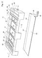
- a grounding plate member 30 is disposed on the lower surface side of the guide portion 8 and extends along the guide portion 8.
- the conveyer guide member 10 is made of a material having an electric resistance not smaller than the electric resistance of the plain paper and the grounding plate member 30 is made of a material having an electric resistance smaller than the electric resistance of the conveyer guide member 10.
- the conveyer guide member 10 is molded as a unitary structure using an ABS resin having an electric resistance of from 1013 ⁇ to 1016 ⁇ (1013 ⁇ in this embodiment) which is not smaller than the electric resistance of the plain paper (generally from 1011 to 1013 ⁇ , but 1013 ⁇ in this embodiment), and has substantially a rectangular box-like shape.
- the upper portion of the conveyer guide member 10 constitutes the guide portion 8, and downwardly extending side walls are formed from the four side edges thereof as a unitary structure.
- the guide portion 8 includes a horizontal portion 32 that extends from the upstream end thereof (right end in Figs. 1 and 4) toward the downstream direction (leftwards in Figs. 1 and 4), a tilted portion 34 that downwardly extends from the downstream end of the horizontal portion 32 toward the downstream direction, and a horizontal portion 36 that extends from the downstream end of the tilted portion 34 up to the downstream end.
- On the guide portion 8 are formed a plurality of ribs 38 that upwardly protrude and extend in the direction in which the plain paper is conveyed (in the direction from the right toward the left in Figs.
- the ribs 38 are so formed that they become high toward the upstream side and low toward the downstream side. If described more closely, the ribs 38 have the same height on the horizontal portion 36 and on the tilted portion 34 but are so tilted on the horizontal portion 32 as to become high toward the upstream end and low toward the downstream end. As shown in Fig. 2, furthermore, there are formed a plurality of ribs 39 in addition to the ribs 38. The ribs 39 have the same height on the upstream side and on the downstream side, and the plain paper on the upstream side is guided substantially by the ribs 38.
- the ribs have height that becomes high toward the upstream side and low toward the downstream side
- a plurality of openings 40 are formed in the guide portion 8 at portions excluding the positions where the ribs 38 and 39 are formed.
- the openings 40 are substantially of a rectangular shape and are formed spanning across the horizontal portion 36 and the tilted portion 34.
- the total area of the openings 40 is set to be more than one-half the area of the guide portion 8.
- the grounding plate member 30 that will be mentioned later is not positioned under the lower surface of the horizontal portion 32 at the upstream end of the conveyer guide member 10.
- the grounding plate member 30 is made of a zinc-plated steel plate (SECC-C specified under JIS) having an electric resistance smaller than 1013 ⁇ (and having an electric resistance of 103 ⁇ in this embodiment).
- the grounding plate member 30 may be made of other metal materials or may be made of, for example, an ABS resin having an electric resistance of from 107 to 1013 ⁇ . According to this embodiment as will be apparent from Figs. 3 and 4, the grounding plate member 30 is disposed with its upper surface in intimate contact with the lower surface of the guide portion 8, or more concretely, with its upper surface in intimate contact with the lower surfaces of the horizontal portion 36 and tilted portion 34 of the guide portion 8.
- the grounding plate member 30 is formed substantially in a rectangular shape and has a horizontal portion 42 and a tilted portion 44. At one side edge of the horizontal portion 42 is integrally formed a side plate 46 that downwardly extends and a grounding portion 48 that is outwardly bent in the horizontal direction at the lower end of the side plate 46.
- the grounding plate member 30 is so mounted that the upper surface of the horizontal portion 42 is in contact with the lower surface of the horizontal portion 36 of the guide portion 8 and the upper surface of the tilted portion 44 is in contact with the lower surface of the tilted portion 34 of the guide portion 8.
- the drawings do not illustrate the constitutions of their mounting portions.
- the grounding plate member 30 may be disposed close to the guide portion 8 but is desirably disposed in contact with, and particularly, in intimate contact with, the guide member 8.
- the grounding portion 48 of the grounding plate member 30 is mounted on a horizontal substrate that is not shown of the printer.
- the grounding plate member 30 is thus grounded.
- the grounding plate member 30 needs not necessarily be grounded but should desirably be grounded.
- the guide portion 8 may often be provided with neither the openings 40 nor one or both of the ribs 38 and 39.
- Figs. 5 and 6 schematically illustrate the conveyer guide member 10 and the grounding plate member 30 according to other embodiments, and in Figs. 5 and 6 the same portions as those of Figs. 1 to 4 are denoted by the same reference numerals.
- the ribs 38 are formed at the upstream end of the guide portion 8.
- the ribs 38 are formed from the upstream end through up to the downstream end of the guide portion 8 like those shown in Figs. 1 to 4.
- the ribs 38 have a height that becomes high toward the upstream side and low toward the downstream side.
- the distance from the upper surface of the grounding plate member 30 to the vertex of the ribs 38 has been specified to be "upstream side a > downstream side b".
- the distance between the vertex of the guide portion 8 and the upper surface of the grounding plate member 30 is 3 mm or greater.
- the guide portion 8 may not often be provided with either one or both of the openings 40 and the ribs 38.
- an apparatus 2 for conveying sheet members in which an insulating member 50 (see two-dotted chain line) is disposed above the guide portion 8 with maintaining a distance with respect to, and extending along, the guide portion 8.
- the insulating member 50 is constituted by an insulating film or a PET (polyethylene terephthalate) film in this embodiment.
- a sheet member guide plate 52 (see two-dotted chain line) is disposed above the guide portion 8 with maintaining a distance with respect to, and extending along, the guide portion 8.
- the insulating member 50 made of an insulating film is stuck to the lower surface that is facing the guide portion, of the sheet member guide plate 52.
- the insulating member 50 may be disposed simply in combination with a conventional conveyer guide member in addition to the case where it is disposed for the constitution in which are combined the conveyer guide member 10 and the grounding plate member 30 explained in Figs. 1 to 6.
- a plain paper that is not shown, sent by the pair of resist rollers 18 passes through the pair of guide plates 20 and further passes through the toner image-transfer position of the photosensitive drum 4, i.e., passes between the photosensitive drum 4 and the transfer roller 16 which is applied with a transfer voltage of a polarity opposite to that of the toner developed on the surface of the photosensitive drum 4.
- the toner developed on the surface of the photosensitive drum 4 is transferred onto the plain paper.
- the plain paper is conveyed toward the downstream direction along the upper surfaces of the ribs 38 and 39 of the guide portion 8 of the conveyer guide member 10.
- the plain paper is further sent to the pair of fixing rollers 22 along the guide plate 28 of the fixing unit 6.
- the plain paper after the toner thereon has been fixed is discharged onto a paper-discharge tray that is not shown, by a pair of discharge rollers 29.
- a high voltage (transfer voltage) is applied to the plain paper sent to the toner image-transfer position of the photosensitive drum 4, so that the toner is transferred thereon.
- the conveyer guide member 10 has an electric resistance not smaller than the electric resistance of the plain paper, and the electric charge is suppressed from abruptly migrating. This makes it possible to prevent the toner on the plain paper from scattering, i.e., prevent the image from being disturbed at a moment when the plain paper comes into contact with the surface of the guide portion 8, and thus, vivid image is guaranteed.
- the grounding plate member 30 having an electric resistance smaller than the electric resistance of the conveyer guide member 10 is disposed on the lower surface side of the guide portion 8, the electric charge that has migrated onto the surface of the guide portion 8 from the plain paper is partly discharged due to the function of the grounding plate member 30. That is, the surface of the guide portion 8 is prevented from being excessively charged with the electric charge from the plain paper. As a result, the plain paper is not repelled by the conveyer guide member 10, and is separated from the photosensitive drum 4 and is conveyed along the guide portion 8 favorably.
- the excess of electric charge of the plain paper is gradually discharged while a relation "potential of the plain paper > potential on the surface of the guide portion 8" being maintained. Therefore, the toner on the plain paper is reliably prevented from scattering either while the plain paper is moving along the surface of the guide portion 8 or when the plain paper separated from the guide portion 8 comes into contact with a metal portion (guide plate 28, heat roller 24, etc.) of the fixing unit 6.
- the grounding plate member 30 Since the grounding plate member 30 is disposed with its upper surface in contact with the lower surface of the guide portion 8, the dielectric effect becomes high between the lower surface of the guide portion 8 and the upper surface of the grounding plate member 30, making it possible to more reliably prevent the plain paper side from being excessively charged. Since the grounding plate member 30 is made of a zinc-plated steel plate which is a metal material, the plain paper is attracted more effectively; i.e., the plain paper is not taken up by the photosensitive drum 4, making it possible to obtain improved separating performance and stabilized conveying performance.
- the contacting portion decreases between the plain paper and the guide portion 8
- the repulsion due to the migration of electric charge decreases and the plain paper is favorably separated.
- the ribs 38 are so formed that they become high toward the upstream side and low toward the downstream side, the plain paper can be stably conveyed on the downstream side. That is, the electric charge of the plain paper tends to decrease as it moves toward the downstream of the guide portion 8 and the attractive force by the grounding plate member 30 tends to decrease.
- the distance is shortened between the plain paper and the grounding plate member 30 on the downstream side, a suitable attractive force can be maintained.
- the insulating member 50 When the insulating member 50 is disposed above the guide portion 8 with maintaining a distance with respect to, and extending along, the guide portion 8, the insulating member 50 is electrically charged to the same polarity as that of the above electric charge of the plain paper and a repulsion is produced between the two. As a result, performance for separating the plain paper is particularly enhanced and conveying performance is stabilized. The above-mentioned effects are obtained even when the grounding plate member 30 is not disposed on the lower surface side of the guide portion 8. Besides, the toner is prevented from scattering. This is because the presence of the insulating member 50 suppresses abrupt migration of the electric charge from the plain paper to the conveyer guide member 10.
- Example 1 a step of forming image was executed using a laser printer that is not shown but that is equipped with the apparatus 2 for conveying sheet members of the form shown in Figs. 1 to 4. Described below is the outline of the step of forming image.
- the surface of the photosensitive drum 4 was uniformly charged to the positive polarity by a charging unit 14. Then, the surface of the photosensitive drum 4 was irradiated with a laser beam based upon image data to be printed and, thus, an electrostatic latent image (negative latent image) was formed.
- a reversal development system was employed, and the magnetic toner charged with the positive polarity which was the same polarity as the electrostatic latent image was adhered to the latent image and was developed.
- the developed toner was transferred onto the sheet member that was sent by the pair of resist rollers 18 to between the photosensitive drum 4 and the transfer roller 16.
- a constant current of 5 ⁇ A was applied to the transfer roller 16, and a transfer voltage of -2 to 3 KV was applied at the time of transfer.
- the sheet member to which the toner had been transferred was conveyed to the downstream direction along the upper surface of the ribs 38 and 39 of the guide portion 8 of the conveyer guide member 10.
- the sheet member was further sent to the pair of fixing rollers 22 along the guide plates 28 of the fixing unit 6.
- the sheet member after the toner thereon had been fixed was discharged onto a paper-discharge tray that is not shown by the pair of discharge rollers 29.
- the sheet member use was made of a plain paper having an electric resistance of 1013 ⁇ .
- the types of the plain papers used will be described later.
- the conveyer guide member 10 used was made of an ABS resin having an electric resistance of 1013 ⁇ .
- the guide portion 8 of the conveyer guide member 10 had openings 40 and ribs 38 and 39.
- the grounding plate member 30 used was made of a zinc-plated steel plate (SECC-C) having an electric resistance of 103 ⁇ .
- SECC-C zinc-plated steel plate
- the grounding plate member 30 was disposed with its upper surface in contact with the lower surface of the guide portion 8 and was grounded.
- the sheet member guide plate 52 was disposed above the guide portion 8, and the insulating film 50 was stuck to the lower surface thereof.
- the insulating film 50 used was made of a PET film having an electric resistance of 1016 ⁇ .
- the distance T13 was 4 mm between the upper surface of the grounding plate member 30 and the vertex of the ribs 38.
- the thickness of the insulating film 50 was 0.188 mm, the distance between the insulating film 50 and the vertex at the upstream end of the ribs 38 was 9 mm in the vertical direction, and the distance between the insulating film 50 and the vertex of the ribs 38 on the downstream side thereof was 15 mm in the vertical direction.
- Example 1 the following three kinds of plain papers were used each having an electric resistance of 1013 ⁇ as mentioned above.
- Example 1 the plain papers onto which the toner had been transferred were all reliably separated without being attracted or taken up by the photosensitive drum 4. There was found no phenomenon in which the plain papers floated upwards in the step in which they were conveyed on the ribs 38 and 39 of the guide portion 8, and it was confirmed that the papers had been conveyed smoothly and reliably along the upper surface thereof. It was confirmed that the image on the plain papers after fixing was vivid, no stain was found on the paper surfaces and the toner had not been scattered at all. That is, according to the apparatus 2 for conveying sheet members of the form employed in Example 1, there was no problem (defect) in regard to the separating performance, conveying performance and toner scattering, and there were obtained results that were sufficiently satisfactory for practical use. The results of the Example 1 are shown in Table 1.
- Example 2 was carried out by using the same apparatus 2 for conveying sheet members as the one used in Example 1 above, but without using the sheet member guide plate 52 and insulating film 50. In other respects, Example 2 was the same as the above-mentioned Example 1, and its details are not repeated here.
- Example 2 very excellent results which were substantially the same as those of Example 1 were obtained with respect to the separating performance, conveying performance and toner scattering.
- the contents were as described in Example 1 above and are not repeated here.
- the results of the Example 2 are shown in Table 1.
- Example 3 was carried out by using the same apparatus 2 for conveying sheet members as the one used in Example 1 above, but without using the sheet member guide plate 52, insulating film 50, and ribs 38 and 39 of the conveyer guide member 10. That is, openings 40 were simply formed in the guide portion 8 of the conveyer guide member 10.
- the grounding plate member 30 was mounted in the same manner as mentioned above. In other respects, Example 3 was the same as the above-mentioned Example 1, and its details are not repeated here.
- Example 3 very excellent results which were substantially the same as those of Examples 1 and 2 were obtained with respect to the separating performance, conveying performance and toner scattering.
- the contents were as described in Example 1 above and are not repeated here.
- the results of the Example 3 are shown in Table 1.
- Example 4 was carried out by using the same apparatus 2 for conveying sheet members as the one used in Example 1 above, but without using the sheet member guide plate 52, insulating film 50, and ribs 38, 39 and openings 40 of the conveyer guide member 10. That is, the guide portion 8 of the conveyer guide member 10 possessed none of the ribs 38, 39 or openings 40, and the upper surface of the guide portion 8 was simply constituted by the horizontal portion 32, tilted portion 34 and horizontal portion 36 only.
- the grounding plate member 30 was mounted in the same manner as mentioned above. In other respects, Example 3 was the same as the above-mentioned Example 1, and its details are not repeated here.
- Example 4 the plain paper after the toner had been transferred thereon exhibited a tendency in which it was separated after taken up by the photosensitive drum. However, the amount of take-up was so small that no jam occurred and there was practically no problem.
- a phenomenon was sometimes observed in which the paper upwardly floated depending upon the kind of the plain paper. However, the frequency was small, and it was confirmed that the plain papers had been smoothly conveyed in the step of forming image. In this respect, therefore, there was no problem in practice.
- a phenomenon was sometimes observed in which the toner sporadically and locally scattered while the plain paper was passing over the guide portion 8.
- Example 5 was carried out by using the same apparatus 2 for conveying sheet members as the one used in Example 1 above, but without using the grounding plate member 30, ribs 38, 39 and openings 40 of the conveyer guide member 10. That is, the guide portion 8 of the conveyer guide member 10 possessed none of the ribs 38, 39 or openings 40, and the upper surface of the guide portion 8 was simply constituted by the horizontal portion 32, tilted portion 34 and horizontal portion 36 only. No grounding plate member 30 was mounted on the lower surface of the guide portion 8. However, the sheet member guide plate 52 and the insulating film 50 were disposed above the guide portion 8.
- Example 5 the distance between the insulating film 50 and the upper surface on the upstream side of the guide portion 8 (upper surface of the horizontal portion 32) was 14 mm in the vertical direction, and the distance between the insulating film 50 and the upper surface on the downstream side of the guide portion 8 (upper surface of the horizontal portion 36) was 17 mm in the vertical direction.
- Example 5 was the same as the above-mentioned Example 1, and its description is not repeated here.
- Example 5 very excellent results were obtained with respect to the separating performance that was substantially equal to that of the aforementioned Examples 1 to 3.
- the contents were the same as those mentioned in Example 1 and are not described here.
- the contents were the same as those of Example 4 and are not repeated here. That is, according to the apparatus 2 for conveying sheet materials of the form used in Example 5, there was no problem (defect) in regard to the separating performance, and there were obtained the results that were practically satisfactory to a sufficient degree. And there was almost no problem with respect to the conveying performance and toner scattering, and there were obtained practically satisfactory results.
- the results of the Example 5 are shown in Table 1.
- Comparative Example 1 was carried out by using the same apparatus 2 for conveying sheet members as the one used in Example 1 above, but without using the sheet member guide plate 52, insulating film 50, ribs 38, 39 and openings 40 of the conveyer guide member 10, and the grounding plate member (apparatus that pertains to the prior art). That is, the guide portion 8 of the conveyer guide member 10 possessed none of the ribs 38, 39 or openings 40, and the upper surface of the guide portion 8 was simply constituted by the horizontal portion 32, tilted portion 34 and horizontal portion 36 only. The grounding plate member 30 was not mounted on the lower surface of the guide portion 8. Moreover, neither the sheet member guide plate 52 nor the insulating film 50 was disposed above the guide portion 8. In other respects, Comparative Example 1 was the same as the above-mentioned Example 1, and its description is not repeated here.
- Comparative Example 1 the phenomenon was frequently observed in which the plain paper onto which the toner has been transferred was taken up by the photosensitive drum 4 after the step of forming image was repeated 50 to 100 times. As a result, most of the plain papers that were taken up were not separated from the photosensitive drum 4 resulting in the occurrence of jamming. After the step of forming image was repeated 50 to 100 times, the phenomenon was frequently observed in which the plain paper floated on the guide portion 8. Moreover, though not so frequently, scattering of the toner was observed on the whole surface or at the front end only of the plain paper.
- Comparative Example 2 was carried out by using the same apparatus 2 for conveying sheet members as the one used in Comparative Example 1 above, but using the conveyer guide member 10 that was formed by using an ABS resin having an electric resistance of 1016 ⁇ . In other respects, Comparative Example 2 was the same as the above-mentioned Example 1, and its description is not repeated here.
Landscapes
- Physics & Mathematics (AREA)
- General Physics & Mathematics (AREA)
- Feeding Of Articles By Means Other Than Belts Or Rollers (AREA)
- Electrostatic Charge, Transfer And Separation In Electrography (AREA)
- Paper Feeding For Electrophotography (AREA)
Applications Claiming Priority (2)
| Application Number | Priority Date | Filing Date | Title |
|---|---|---|---|
| JP5187938A JPH0741205A (ja) | 1993-07-29 | 1993-07-29 | シート部材搬送装置 |
| JP187938/93 | 1993-07-29 |
Publications (2)
| Publication Number | Publication Date |
|---|---|
| EP0636947A2 true EP0636947A2 (de) | 1995-02-01 |
| EP0636947A3 EP0636947A3 (de) | 1995-04-12 |
Family
ID=16214809
Family Applications (1)
| Application Number | Title | Priority Date | Filing Date |
|---|---|---|---|
| EP94111510A Withdrawn EP0636947A3 (de) | 1993-07-29 | 1994-07-22 | Fördergerät für blattförmiges Material. |
Country Status (3)
| Country | Link |
|---|---|
| US (1) | US5477314A (de) |
| EP (1) | EP0636947A3 (de) |
| JP (1) | JPH0741205A (de) |
Cited By (2)
| Publication number | Priority date | Publication date | Assignee | Title |
|---|---|---|---|---|
| EP0961180A3 (de) * | 1998-05-29 | 2001-06-20 | Xerox Corporation | Einheit zum transportieren von Briefumschlägen |
| EP2525260A3 (de) * | 2011-05-17 | 2016-10-26 | Oki Data Corporation | Bilderzeugungsvorrichtung |
Families Citing this family (13)
| Publication number | Priority date | Publication date | Assignee | Title |
|---|---|---|---|---|
| JP2901115B2 (ja) * | 1992-11-13 | 1999-06-07 | 三田工業株式会社 | 定着装置 |
| JPH0741204A (ja) * | 1993-07-29 | 1995-02-10 | Mita Ind Co Ltd | 画像形成装置 |
| JPH10240052A (ja) * | 1997-02-28 | 1998-09-11 | Brother Ind Ltd | 画像形成装置 |
| JP2006146117A (ja) * | 2004-10-20 | 2006-06-08 | Brother Ind Ltd | 画像形成装置 |
| JP2013242534A (ja) * | 2012-04-23 | 2013-12-05 | Canon Inc | 定着装置 |
| JP6047980B2 (ja) | 2012-07-26 | 2016-12-21 | ブラザー工業株式会社 | 記録シートガイド構造およびカートリッジ |
| JP5829638B2 (ja) * | 2013-02-08 | 2015-12-09 | 株式会社沖データ | 定着装置及び画像形成装置 |
| JP6460047B2 (ja) * | 2016-05-20 | 2019-01-30 | 京セラドキュメントソリューションズ株式会社 | 定着装置およびそれを備えた画像形成装置 |
| JP7075166B2 (ja) * | 2016-10-21 | 2022-05-25 | 京セラドキュメントソリューションズ株式会社 | 画像形成装置 |
| JP6631484B2 (ja) * | 2016-11-29 | 2020-01-15 | 京セラドキュメントソリューションズ株式会社 | 転写ユニット及びそれを備えた画像形成装置 |
| JP7031192B2 (ja) * | 2017-09-25 | 2022-03-08 | ブラザー工業株式会社 | 画像形成装置 |
| JP7251192B2 (ja) * | 2019-02-14 | 2023-04-04 | 富士フイルムビジネスイノベーション株式会社 | 用紙案内部材および画像形成装置 |
| JP7746723B2 (ja) * | 2021-08-05 | 2025-10-01 | 京セラドキュメントソリューションズ株式会社 | 画像形成装置 |
Family Cites Families (10)
| Publication number | Priority date | Publication date | Assignee | Title |
|---|---|---|---|---|
| JPS59125764A (ja) * | 1983-01-07 | 1984-07-20 | Canon Inc | 転写式画像形成装置 |
| JPS60200273A (ja) * | 1984-03-24 | 1985-10-09 | Minolta Camera Co Ltd | 転写紙の分離搬送装置 |
| EP0292359B1 (de) * | 1987-05-06 | 1992-09-09 | Fujitsu Limited | Elektrophotographisches Bildaufzeichnungsgerät |
| JPS63285572A (ja) * | 1987-05-18 | 1988-11-22 | Ricoh Co Ltd | 電子写真装置 |
| JP2666073B2 (ja) * | 1988-09-19 | 1997-10-22 | キヤノン株式会社 | 画像形成装置 |
| JPH03228074A (ja) * | 1989-08-09 | 1991-10-09 | Ricoh Co Ltd | 転写体搬送案内部材 |
| JPH0428643A (ja) * | 1990-05-22 | 1992-01-31 | Tokyo Electric Co Ltd | 電子写真装置の用紙搬送ガイド |
| JP3073030B2 (ja) * | 1990-06-29 | 2000-08-07 | 株式会社リコー | 転写装置 |
| JP2840483B2 (ja) * | 1991-06-28 | 1998-12-24 | キヤノン株式会社 | 画像形成装置 |
| JP3296838B2 (ja) * | 1991-11-14 | 2002-07-02 | 株式会社リコー | 画像形成装置 |
-
1993
- 1993-07-29 JP JP5187938A patent/JPH0741205A/ja active Pending
-
1994
- 1994-07-11 US US08/272,737 patent/US5477314A/en not_active Expired - Lifetime
- 1994-07-22 EP EP94111510A patent/EP0636947A3/de not_active Withdrawn
Cited By (2)
| Publication number | Priority date | Publication date | Assignee | Title |
|---|---|---|---|---|
| EP0961180A3 (de) * | 1998-05-29 | 2001-06-20 | Xerox Corporation | Einheit zum transportieren von Briefumschlägen |
| EP2525260A3 (de) * | 2011-05-17 | 2016-10-26 | Oki Data Corporation | Bilderzeugungsvorrichtung |
Also Published As
| Publication number | Publication date |
|---|---|
| JPH0741205A (ja) | 1995-02-10 |
| US5477314A (en) | 1995-12-19 |
| EP0636947A3 (de) | 1995-04-12 |
Similar Documents
| Publication | Publication Date | Title |
|---|---|---|
| US5477314A (en) | Sheet conveying apparatus with guide member | |
| US5594539A (en) | Paper guide device for image forming apparatus | |
| US4984024A (en) | Image transfer unit for image recording apparatus | |
| US5926682A (en) | Image forming apparatus | |
| US5040030A (en) | Precise loading blade and method for making same | |
| JPH07248690A (ja) | 転写装置 | |
| US5930569A (en) | Developer rolls system with reduced edge image defects | |
| US4782358A (en) | Device for separating transfer sheet | |
| US5729810A (en) | Overcoated transfer roller for transferring developed images from one surface to another | |
| JP3743475B2 (ja) | 画像形成装置 | |
| US11188013B2 (en) | Photoreceptor stripper fingers with an improved profile for ultra-light weight media | |
| US4079697A (en) | Electrode conductive roller developing device | |
| JP4143268B2 (ja) | 画像形成装置 | |
| JPH103243A (ja) | 画像形成装置の作像ユニット | |
| JP3210198B2 (ja) | コロナ放電装置 | |
| JP2002068522A (ja) | 画像形成装置 | |
| JP2559255Y2 (ja) | 画像形成装置 | |
| JPH0546033A (ja) | 転写材担持体への用紙ガイド装置 | |
| JP2005077541A (ja) | 転写ローラ | |
| JPH06308846A (ja) | 画像形成装置 | |
| JPH1195564A (ja) | 画像形成装置 | |
| JPH10129875A (ja) | 用紙搬送装置 | |
| JPH103246A (ja) | 画像形成装置の作像ユニット | |
| JPH0428643A (ja) | 電子写真装置の用紙搬送ガイド | |
| JPH04112149A (ja) | 除電部材 |
Legal Events
| Date | Code | Title | Description |
|---|---|---|---|
| PUAI | Public reference made under article 153(3) epc to a published international application that has entered the european phase |
Free format text: ORIGINAL CODE: 0009012 |
|
| AK | Designated contracting states |
Kind code of ref document: A2 Designated state(s): DE FR GB IT |
|
| PUAL | Search report despatched |
Free format text: ORIGINAL CODE: 0009013 |
|
| AK | Designated contracting states |
Kind code of ref document: A3 Designated state(s): DE FR GB IT |
|
| 17P | Request for examination filed |
Effective date: 19950623 |
|
| 17Q | First examination report despatched |
Effective date: 19950725 |
|
| STAA | Information on the status of an ep patent application or granted ep patent |
Free format text: STATUS: THE APPLICATION IS DEEMED TO BE WITHDRAWN |
|
| 18D | Application deemed to be withdrawn |
Effective date: 19960206 |