EP0641132A1 - Appareil d'affichage et de prise de vues stéréoscopiques - Google Patents
Appareil d'affichage et de prise de vues stéréoscopiques Download PDFInfo
- Publication number
- EP0641132A1 EP0641132A1 EP94113244A EP94113244A EP0641132A1 EP 0641132 A1 EP0641132 A1 EP 0641132A1 EP 94113244 A EP94113244 A EP 94113244A EP 94113244 A EP94113244 A EP 94113244A EP 0641132 A1 EP0641132 A1 EP 0641132A1
- Authority
- EP
- European Patent Office
- Prior art keywords
- parallax
- viewer
- calculator
- fixating
- image
- Prior art date
- Legal status (The legal status is an assumption and is not a legal conclusion. Google has not performed a legal analysis and makes no representation as to the accuracy of the status listed.)
- Granted
Links
Images


Classifications
-
- H—ELECTRICITY
- H04—ELECTRIC COMMUNICATION TECHNIQUE
- H04N—PICTORIAL COMMUNICATION, e.g. TELEVISION
- H04N13/00—Stereoscopic video systems; Multi-view video systems; Details thereof
- H04N13/30—Image reproducers
- H04N13/366—Image reproducers using viewer tracking
- H04N13/383—Image reproducers using viewer tracking for tracking with gaze detection, i.e. detecting the lines of sight of the viewer's eyes
-
- H—ELECTRICITY
- H04—ELECTRIC COMMUNICATION TECHNIQUE
- H04N—PICTORIAL COMMUNICATION, e.g. TELEVISION
- H04N13/00—Stereoscopic video systems; Multi-view video systems; Details thereof
-
- H—ELECTRICITY
- H04—ELECTRIC COMMUNICATION TECHNIQUE
- H04N—PICTORIAL COMMUNICATION, e.g. TELEVISION
- H04N13/00—Stereoscopic video systems; Multi-view video systems; Details thereof
- H04N13/10—Processing, recording or transmission of stereoscopic or multi-view image signals
- H04N13/106—Processing image signals
- H04N13/111—Transformation of image signals corresponding to virtual viewpoints, e.g. spatial image interpolation
- H04N13/117—Transformation of image signals corresponding to virtual viewpoints, e.g. spatial image interpolation the virtual viewpoint locations being selected by the viewers or determined by viewer tracking
-
- H—ELECTRICITY
- H04—ELECTRIC COMMUNICATION TECHNIQUE
- H04N—PICTORIAL COMMUNICATION, e.g. TELEVISION
- H04N13/00—Stereoscopic video systems; Multi-view video systems; Details thereof
- H04N13/10—Processing, recording or transmission of stereoscopic or multi-view image signals
- H04N13/106—Processing image signals
- H04N13/122—Improving the three-dimensional [3D] impression of stereoscopic images by modifying image signal contents, e.g. by filtering or adding monoscopic depth cues
-
- H—ELECTRICITY
- H04—ELECTRIC COMMUNICATION TECHNIQUE
- H04N—PICTORIAL COMMUNICATION, e.g. TELEVISION
- H04N13/00—Stereoscopic video systems; Multi-view video systems; Details thereof
- H04N13/10—Processing, recording or transmission of stereoscopic or multi-view image signals
- H04N13/106—Processing image signals
- H04N13/128—Adjusting depth or disparity
-
- H—ELECTRICITY
- H04—ELECTRIC COMMUNICATION TECHNIQUE
- H04N—PICTORIAL COMMUNICATION, e.g. TELEVISION
- H04N13/00—Stereoscopic video systems; Multi-view video systems; Details thereof
- H04N13/20—Image signal generators
- H04N13/204—Image signal generators using stereoscopic image cameras
- H04N13/239—Image signal generators using stereoscopic image cameras using two two-dimensional [2D] image sensors having a relative position equal to or related to the interocular distance
-
- H—ELECTRICITY
- H04—ELECTRIC COMMUNICATION TECHNIQUE
- H04N—PICTORIAL COMMUNICATION, e.g. TELEVISION
- H04N13/00—Stereoscopic video systems; Multi-view video systems; Details thereof
- H04N13/20—Image signal generators
- H04N13/296—Synchronisation thereof; Control thereof
-
- H—ELECTRICITY
- H04—ELECTRIC COMMUNICATION TECHNIQUE
- H04N—PICTORIAL COMMUNICATION, e.g. TELEVISION
- H04N13/00—Stereoscopic video systems; Multi-view video systems; Details thereof
- H04N13/30—Image reproducers
- H04N13/366—Image reproducers using viewer tracking
- H04N13/376—Image reproducers using viewer tracking for tracking left-right translational head movements, i.e. lateral movements
-
- H—ELECTRICITY
- H04—ELECTRIC COMMUNICATION TECHNIQUE
- H04N—PICTORIAL COMMUNICATION, e.g. TELEVISION
- H04N13/00—Stereoscopic video systems; Multi-view video systems; Details thereof
- H04N13/30—Image reproducers
- H04N13/366—Image reproducers using viewer tracking
- H04N13/38—Image reproducers using viewer tracking for tracking vertical translational head movements
-
- H—ELECTRICITY
- H04—ELECTRIC COMMUNICATION TECHNIQUE
- H04N—PICTORIAL COMMUNICATION, e.g. TELEVISION
- H04N13/00—Stereoscopic video systems; Multi-view video systems; Details thereof
- H04N13/10—Processing, recording or transmission of stereoscopic or multi-view image signals
- H04N13/106—Processing image signals
- H04N13/167—Synchronising or controlling image signals
-
- H—ELECTRICITY
- H04—ELECTRIC COMMUNICATION TECHNIQUE
- H04N—PICTORIAL COMMUNICATION, e.g. TELEVISION
- H04N13/00—Stereoscopic video systems; Multi-view video systems; Details thereof
- H04N13/10—Processing, recording or transmission of stereoscopic or multi-view image signals
- H04N13/189—Recording image signals; Reproducing recorded image signals
-
- H—ELECTRICITY
- H04—ELECTRIC COMMUNICATION TECHNIQUE
- H04N—PICTORIAL COMMUNICATION, e.g. TELEVISION
- H04N13/00—Stereoscopic video systems; Multi-view video systems; Details thereof
- H04N13/30—Image reproducers
- H04N13/332—Displays for viewing with the aid of special glasses or head-mounted displays [HMD]
- H04N13/337—Displays for viewing with the aid of special glasses or head-mounted displays [HMD] using polarisation multiplexing
-
- H—ELECTRICITY
- H04—ELECTRIC COMMUNICATION TECHNIQUE
- H04N—PICTORIAL COMMUNICATION, e.g. TELEVISION
- H04N13/00—Stereoscopic video systems; Multi-view video systems; Details thereof
- H04N13/30—Image reproducers
- H04N13/346—Image reproducers using prisms or semi-transparent mirrors
-
- H—ELECTRICITY
- H04—ELECTRIC COMMUNICATION TECHNIQUE
- H04N—PICTORIAL COMMUNICATION, e.g. TELEVISION
- H04N13/00—Stereoscopic video systems; Multi-view video systems; Details thereof
- H04N13/30—Image reproducers
- H04N13/363—Image reproducers using image projection screens
-
- H—ELECTRICITY
- H04—ELECTRIC COMMUNICATION TECHNIQUE
- H04N—PICTORIAL COMMUNICATION, e.g. TELEVISION
- H04N13/00—Stereoscopic video systems; Multi-view video systems; Details thereof
- H04N2013/0074—Stereoscopic image analysis
- H04N2013/0081—Depth or disparity estimation from stereoscopic image signals
Definitions
- the present invention relates to a stereoscopic image pickup and display apparatus for recording and displaying a stereoscopic image of an object.
- the apparatus shown comprises two ordinary cameras mounted on two separate universal heads, the two cameras corresponding to the left and right eyes of a human.
- the cameras are secured to rotation controllers 3 and 4, respectively, so that they are rotatable in a horizontal plane.
- the spacing between the two cameras is adjustable on a camera spacing controller 5.
- the entire camera construction is supported on a tripod 6.
- Top plan views of this prior art stereoscopic image pickup apparatus are given in Figures 11(a) and 11(b): (a) shows the apparatus in a parallel shooting position where the optic axes of the cameras are set parallel to each other, and (b) illustrates a converging shooting position where the optic axes of the cameras are tilted so that they intersect each other.
- the rotation controllers 3 and 4 are operated to rotate the respective cameras and set them in the parallel shooting or the converging shooting position.
- the camera spacing is adjustable by varying Wc. In shooting an object in three dimensions, the camera spacing Wc and the distance dx to the converging point greatly affect the quality of the resulting stereoscopic image.
- the camera spacing Wc affects the size of the object to be displayed as well as the amount of the horizontal parallax to be reproduced.
- the distance dx to the converging point has a significant effect on the distortion of the recorded image as well as on the amount of the horizontal parallax (which affects the binocular fusing range of the viewer).
- FIG. 12 is a schematic diagram of a prior art stereoscopic image display apparatus for reproducing a stereoscopic image signal recorded by the stereoscopic image pickup apparatus.
- two separate images, one for each eye, recorded by the stereoscopic image pickup apparatus are reproduced by projectors 9 and 10, are polarized through two polarizers 11 oriented perpendicular to each other, and are focused onto a screen 12.
- the right-eye image is reflected only into the viewer's right eye and the left-eye image only into the viewer's left eye.
- Figure 13 shows the screen of the stereoscopic image display apparatus as viewed from above.
- IL and IR represent the left- and right-eye spot images obtained by the stereoscopic image pickup apparatus
- a viewer with an interocular distance of We perceives the object virtually lying at the intersection C1 between the visual axes.
- the viewer can perceive the depth of the displayed image by binocular stereoscopic vision.
- images displayed on two CRTs with crossed polarizers are combined by a half-silvered mirror without using a screen, and the combined image is viewed through glasses with the corresponding polarizers.
- the principle of making the viewer perceive the depth of an image is the same.
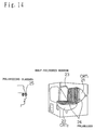
- FIG. 15 This diagram explains how a viewer perceives image depth based on the parallax between his left and right eyes.
- A, B, and P represent objects (points)
- CL is the center of rotation of the viewer's left eye 26
- CR is the center of rotation of the viewer's right eye 27
- FL and FR are foveae of the viewer's left and right eyes, respectively (the fovea is the region in the retina where there is the greatest acuity of vision; when a human views an object, an image of the object is focused onto the fovea ).
- the viewer focuses his eyes on the point P.
- the left and right eyeballs move so that images of the point P are focused on the respective foveae , FL and FR.
- images of the point A situated nearer to the eyes than the point P are focused on AL and AR on the retinas of the left and right eyes.
- images of the point B farther from the point P are focused on BL and BR on the retinas of the left and right eyes.
- the distance ALBL between the images of the point A and point B formed on the retina of one eye is different from the corresponding distance ARBR in the other eye. This difference in distance corresponds to the distance between the point A and point B in the direction of depth.
- a human calculates this difference in his brain to perceive the depthwise position of an object, i.e., LAB in Figure 15. As the distance to an object increases, a human's perception of the absolute distance LA, LB to the point A, B becomes less sensitive while his perception of the relative distance LAB becomes more sensitive.
- a human can calculate the depth when the amount of the binocular parallax ⁇ is within a range of ⁇ 0.5°; if the depthwise distance becomes larger (the absolute value of the binocular parallax ⁇ becomes larger), the sense of depthwise distance decreases, and if the distance increases further, the object will appear double, making it difficult to perceive the depth and the image very unpleasant to view.
- the points A, B, and P in Figure 15 are displayed on the stereoscopic image display apparatus of Figure 14.
- the displacement between the fixating position (CRT surface) of the eye lens and the depthwise position of the presented image becomes larger.
- Human vision has a threshold of tolerance for the displacement between the CRT surface and the stereoscopic image display position. If the displacement becomes larger than this threshold, images of the intended object cannot be focused on the foveae of both eyes, and the viewer perceives them as a double image.
- the prior art stereoscopic image display apparatus has not been able to present images that are easy on the eyes and that have good visibility.
- the present invention provides a stereoscopic image pickup and display apparatus consisting of a stereoscopic image pickup apparatus and a stereoscopic image display apparatus in combination:
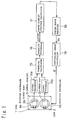
- the stereoscopic image pickup apparatus comprises an image pickup device for capturing an object from different viewpoints; a converging angle moving mechanism for varying the converging angle of the image pickup device; a signal processor for extracting image data from the image pickup device; a parallax calculator for calculating the parallax of an image by using an output of the signal processor; a parallax processor for detecting the smallest value (the parallax of the nearest object) out of outputs from the parallax calculator; a depth display position calculator for calculating from an output of the parallax processor the depthwise position of an object to be reproduced at the nearest point when a captured image is displayed by the stereoscopic image display apparatus; a fusing range verifier for verifying on the basis of an output of the depth display position calculator whether the nearest point is within a fusional range of
- the binocular parallax of a captured image is detected, based on which the depthwise position of an object at the nearest point to the viewer is calculated, and the converging angle moving mechanism is controlled so that the nearest point comes within the fusional range of the viewer viewing the reproduced image; furthermore, from the binocular parallax of the image, an optimum fixating point is calculated that enables the viewer to perceive the stereoscopic depth of the object over the widest possible range, and control is performed so that the fixating point is reproduced at the surface of the stereoscopic image display or at a designated distance from the surface.
- Figure 1 is a diagram showing the configuration of an image pickup section in a stereoscopic image pickup and display apparatus according to a first embodiment of the present invention.
- the numerals 1 and 2 are lenses
- 3a and 3b are camera bodies
- 4a and 4b are rotation controllers
- 5 is a camera spacing controller.
- the numerals 14a and 14b are signal processors each for converting the camera signal into the luminance signal
- 15 is a parallax calculator for calculating horizontal parallax from left and right images
- 16 is a parallax processor for detecting the smallest parallax
- 17 is a depth display position calculator for calculating the spatial position of an object nearest to the viewer
- 18 is a fusing range verifier for verifying whether the spatial position of the object nearest to the viewer is within the fusing range of the viewer's eyes
- 19 is a converging angle controller for controlling the rotation controllers 4a, 4b so that the spatial position of the object nearest to the viewer comes within the fusing range of the viewer's eyes.
- Figure 2(a) shows a model of the image pickup system.
- the image pickup cameras are arranged symmetric to each other with their optic axes directed to a converging point F (0, dx, 0).
- F converging point
- the centerpoint of the line joining the two cameras is the origin
- the two cameras are arranged along the x-axis
- the direction of depth is plotted along the y-axis
- the direction of height along the z-axis The left and right lenses are positioned at (-Wc, 0, 0) and (Wc, 0, 0), respectively, on the x-axis.
- each lens with respect to the imaging surface (the position of the imaging device or film) 7, 8 is denoted by f.
- Figure 2(b) shows a model of the display system (a model of a stereoscopic image display apparatus).
- the origin represents the centerpoint between the two eyes of the viewer
- the line joining the centers of the two eyes is taken as the x-axis
- the direction of depth is plotted along the y-axis
- the direction of height along the z-axis the direction of height along the z-axis.
- the positions of the left and right eyes be represented by coordinates (-We, 0, 0) and (We, 0, 0), respectively, and the positions of reproduced spot images be designated Pr for the right eye and Pl for the left eye. Then, the viewer will perceive the spot image lying at the point of intersection, P, of the line joining Pr and (We, 0, 0) and the line joining Pl and (-We, 0, 0).
- the parameter dx in the image pickup apparatus is controlled so that when a stereoscopic image is displayed by the stereoscopic display apparatus, the stereoscopic image can be displayed within the range in which the viewer can fuse the left and right images into a signal image. It is therefore necessary that the condition that enables the viewer to achieve binocular fusion be first determined in the geometry shown in Figure 2(b).
- Figure 2(b) suppose, for example, that the viewer is viewing the point P. In this case, the actual images are focused on the display screen 12. However, the visual axes of both eyes are directed to the point P. Crossing both eyes inward to view a near object is known as convergence eyemovement, and the point P is called the converging point.
- the convergence eyemovement is controlled using the eye's focus information as well as the information concerning the projected position of the point P on the retina.
- Allowable ranges for the fixating position of the eye (hereinafter called the accomodation point) and the position of the converging point (hereinafter called the convergence) based on the projected positions on the retinas were measured.
- the results are shown in Figure 3.
- the convergence plotted along the abscissa is represented by the distance between the viewer and the intersection of the visual axes of both eyes, and the accomodation point plotted along the ordinate is represented by the distance (measured in diopter, the reciprocal of the distance) between the viewer and the position on which the lenses of the eyeballs are focused.
- the straight line upward to the right at an angle of 45° represents the condition where the convergence coincides with the accomodation point, the shaded area shows the allowable range within the depth of focus of the eye, and ⁇ indicates the fusional limits when an image is presented for 0.5 second. Within the region between the upper and lower fusional limits, the viewer can fuse the stereoscopic images and no double image will occur. In shooting an object, therefore, control is performed so that dx in Figure 2 will have the largest possible value while satisfying the condition that enables all stereoscopic images to be reproduced within the fusional range.
- the parallax calculator 15 shown in Figure 1 calculates a parallax map (a three-dimensional map) from the left- and right-eye images output from the signal processors 14a and 14b.
- a parallax map (a three-dimensional map) from the left- and right-eye images output from the signal processors 14a and 14b.
- a correlation matching method that calculates the correlations of luminance patterns between left and right images
- an edge information matching method that involves matching the edge information between left and right images.
- the example hereinafter described employs the correlation matching method that calculates the correlations of luminance patterns.
- the operation of the parallax calculator 15 will be described in detail with reference to Figure 4. In Figure 4, consider left and right images each of N x M size.
- the component that directly indicates the depthwise position is ⁇ x.
- the left image as the reference, if the value of the binocular parallax is positive, the right image is positioned to the right, and the left image to the left, with respect to the reference image, the object lying farther than the depthwise position at which the binocular parallax is zero; on the other hand, if the value of the binocular parallax is negative, this indicates that the object is positioned nearer than the depthwise position with zero binocular parallax.
- the parallax processor 16 Based on the thus obtained parallax map (showing parallax ⁇ x calculated at each coordinate position on the entire screen), the parallax processor 16 extracts the smallest parallax value (the parallax of the object reproduced at the position nearest to the viewer) from the entire screen, the extracted value being denoted as ⁇ xmin.
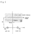
- the depth display position calculator 17 calculates the depth reproduction position Ypmin of the stereoscopic image on the stereoscopic image presentation diagram shown in Figure 5, using the following equation.
- Ypmin represents the y-coordinate of the distance from the origin of the display coordinate system to the position of the object in fixating.
- the viewing distance when the viewing distance is 71 cm or greater, the viewer can fuse images within the range from infinity to F(ds)min.
- the binocular fusing range is also limited by the upper curve in Figure 3, thus limiting the binocular fusing range to within the distance from F(ds)max to F(ds)min.
- the following description deals with a case where the viewing distance is 71 cm or greater.
- the fusing range verifier 18 judges whether Ypmin lies on the boundary of the binocular fusing range.
- the fusing range verifier 18 adds ⁇ dx to the current dx value and supplies the resulting new dx value to the converging angle controller 19.
- ⁇ to be described later Figure 6
- dx need not be updated.
- dx is obtained by eliminating ⁇ S from equations in Mathematical 5 and 2, substituting F(ds)min for Yp, and solving the result for dx.
- the converging angle controller 19 controls the rotation controllers 4a and 4b to position the camera bodies 3a and 3b so that their optic axes are directed to the converging point shown in Figure 2(a).
- dx is updated in increments of ⁇ dx, but in the case of the condition shown by Mathematical 8, the value of dx_0 given by Mathematical 9 may be directly substituted into dx.
- control is performed so that Ypmin, the point in the object nearest to the viewer, becomes equal to F(ds)min, a point near the limit of the fusing range.
- Ypmin is within the binocular fusing range under the condition that makes the optic axes of the camera bodies 3a and 3b parallel to each other, then the optic axes of the two cameras are maintained parallel to each other.
- the parallax of captured images is calculated, and the optic axes of the stereoscopic pickup cameras are controlled so that the smallest parallax value can be reproduced within the fusing range of the viewer's eyes.
- the viewer can fuse the reproduced stereoscopic images over the widest possible range.
- the initial value of dx is set as dx_ ⁇ .
- Figure 7 is a diagram showing the configuration of an image pickup section in a stereoscopic image pickup and display apparatus according to a second embodiment of the present invention.
- the numerals 1 and 2 are lenses
- 3a and 3b are camera bodies
- 4a and 4b are rotation controllers
- 5 is a camera spacing controller
- 17 is a depth display position calculator for calculating the spatial position of an object nearest to the viewer
- 19 is a converging angle controller for controlling the rotation controllers 4a and 4b so that the spatial position of the object nearest to the viewer comes within the fusing range of the viewer's eyes.
- the differences from the first embodiment are that the coordinates x0, y0 of the nearest object are directly input to the depth display position calculator 17, and that a fusing range determiner is provided that calculates the value of dx to bring the object nearest to the viewer into the fusing range of the viewer's eyes.
- the coordinates of the point in an object nearest to the cameras are set as N (x0, y0, z0).
- the operator measures this distance and inputs x0, y0 to the depth display position calculator 17.
- These values may be input using a calculator keyboard or any other device that can enter numeric data.
- the depth display position calculator 17 calculates the y-coordinate of the display position of the point N in the stereoscopic image reproduction/display coordinate system shown in Figure 2(b). The calculation is made using the following equation.
- ⁇ S is determined in accordance with Mathematical 2, as in the first embodiment of the invention.
- the converging angle controller 19 calculates the optic axis angle ⁇ of the two cameras.
- the angle ⁇ is the same as that shown in Figure 6.
- the rotation controllers 4a and 4b control the optic axes of the respective cameras so that the thus determined angle ⁇ can be provided.
- the position of the object nearest to the cameras is input, and the converging point dx is determined so that the object can be reproduced within the fusing range of the viewer's eyes, in accordance with which the optic axes of the stereoscopic image pickup cameras are controlled.
- the viewer can fuse the reproduced stereoscopic images over the widest possible range.
- the values x0, y0 are input to the depth display position calculator 17 manually by the operator, but these values may be input automatically by using a distance-measuring device such as a ultrasonic sensor. Also, x0 may be fixed to a predetermined value, and the value of y0 only may be input.
- Figure 8 is a diagram showing the configuration of an image pickup section in a stereoscopic image pickup and display apparatus according to a third embodiment of the present invention.
- the block construction is the same as that shown in Figure 1.
- the numerals 1 and 2 are lenses
- 3a and 3b are camera bodies
- 4a and 4b are rotation controllers
- 5 is a camera spacing controller
- 14a and 14b are signal processors each for converting the camera signal into the luminance signal
- 15 is a parallax calculator for calculating horizontal parallax from left and right images
- 16 is a parallax processor for detecting the smallest parallax
- 17 is a depth display position calculator for calculating the spatial position of an object farthest from the viewer
- 18 is a fusing range verifier for verifying whether the spatial position of the object farthest from the viewer is within the fusing range of the viewer's eyes.
- 19 is a converging angle controller for controlling the rotation controllers 4a, 4b so that the spatial position of the object farthest from the viewer comes within the fusing range of the viewer's eyes.
- the differences from the first embodiment are that the parallax processor 16 calculates the largest parallax value, that the depth display position calculator 17 calculates the spatial position of the object farthest from the viewer, and that the fusing range verifier 18 verifies whether the spatial position of the object farthest from the viewer is within the fusing range of the viewer's eyes.
- control was performed based on the smallest parallax value and the nearest object.
- the viewer's viewing distance was set greater than 71 cm
- the binocular fusing range was from ⁇ to F(ds)min
- ds was controlled so as to bring F(ds)min within the binocular fusing range of the viewer.
- the distance ranging from F(ds)max to F(ds)min is the binocular fusing range, as described earlier; if F(ds)min is to be brought within the fusing range, control can be performed in the same manner as described in the first embodiment, but in the third embodiment of the invention, control is performed in such a manner as to bring F(ds)max within the binocular fusing range.
- the parallax calculator 15 calculates a parallax map by using the image signals obtained from the camera bodies 3a, 3b and signal processors 14a, 14b, as in the first embodiment of the invention. The method of calculation is exactly the same as that employed in the first embodiment. Based on the parallax map, the parallax processor calculates the largest parallax value ⁇ xmax (the parallax of the object farthest from the cameras). Next, the depth display position calculator 17, using Mathematical 5, calculates the position at which the farthest object is to be reproduced for display.
- the coordinate system used here is the same as the stereoscopic image display coordinate system shown in Figure 2(b).
- the fusing range verifier 18 supplies the current dx value as-is to the converging angle controller 19. Further, if Ypmax satisfies the relation [Mathematical 13] Ypmax ⁇ F(ds)max- ⁇ F the display position of reproduced Ypmax is completely inside the binocular fusing range.
- the current dx is reduced by ⁇ dx, and the result is taken as the new dx. If the value obtained by subtracting ⁇ F from the new dx is smaller than dx1 (>0, to be described hereinafter), then dx1 is taken as the new dx. Calculation of dx1 will now be described.
- the fusing range verifier 18 calculates dx such that the y-coordinate of Ypmax agrees with F(ds)max in Figure 5, and takes the result as dx1.
- the converging angle controller 19 controls the rotation controllers 4a and 4b to position the camera bodies 3a and 3b so that the camera optic axes are directed to the converging point shown in Figure 2(a).
- dx is updated in increments of ⁇ dx, but in the case of the condition shown by Mathematical 15, the value of dx_1 given by Mathematical 14 may be directly substituted into dx.
- control is performed so that Ypmax, the point in the object farthest from the viewer, becomes equal to F(ds)max, the far point limit of the fusing range.
- Ypmax does not come within the binocular fusing range even under the condition that makes the optic axes of the camera bodies 3a and 3b parallel to each other, the optic axes of the two cameras are maintained parallel to each other.
- the parallax of captured images is calculated, and the optic axes of the stereoscopic image pickup cameras are controlled so that the largest parallax value can be reproduced within the fusing range of the viewer's eyes.
- the viewer can fuse the reproduced stereoscopic images over the widest possible range.
- noise may be introduced into the output of the parallax calculator 15, depending on the condition of the object being shot; therefore, the output of the parallax calculator 15 may be passed through a time-domain low-pass filter to reduce the noise. Further, control of the two cameras need only be performed slowly; to prevent abrupt movements, ⁇ xmin output from the parallax processor 16, dx output from the fusing range verifier 18, or dx output from the fusing range determiner 20 may be low-pass filtered in the direction of time.
- Figure 16 is a diagram showing the configuration of a display section in a stereoscopic image pickup and display apparatus according to a fourth embodiment of the present invention.
- the numeral 29 is a parallax calculator
- 30 is an fixating point calculator
- 31 is a parallax controller
- 32 is an image display. The operation of the thus constructed stereoscopic image display of the present embodiment will be described below.
- the parallax calculator 29 calculates a parallax map (a three-dimensional map) from left- and right-eye images.
- the same calculation method as used in the first embodiment will be used here, such as the correlation matching method that calculates the correlations of luminance patterns between the left and right images. That is, in Figure 4, consider a block window of n x n pixels (3 x 3 pixels in the figure) in the left image. Then, the same image as shown in the block window is located in the right image by using a window of the same size. In the displacement ( ⁇ x, ⁇ y) between the left and right block positions, the horizontal displacement component ⁇ x represents the binocular parallax of the left and right images at the center coordinate of the block window.
- a parallax map (showing depthwise distance at each position on the screen) can be obtained for the entire screen.
- the fixating point calculator 30 calculates an average value for the parallax over the entire screen or a weighted average value ⁇ xave with greater weight at the center of the screen.
- Figure 17 shows examples of positions in the screen and their associated weight coefficients.
- the screen of X x Y size is simply divided into two regions, a center region of X/2 x Y/2 size and the remaining region, and a weight coefficient K2 is assigned to the center region and K1 to the remaining region.
- Such regions may be in other shapes such as a circular shape, and the weight coefficient may be varied continuously from the periphery toward the center.
- the parallax controller 31 controls the horizontal read timing of the left and right images and moves the images in horizontal directions.
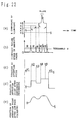
- Figure 18 shows a horizontal scanning period of the video signal. Points AL and AR indicate the same point in the same object in the left and right images, respectively.
- the binocular parallax ⁇ X at the point A, first mentioned, is shown in the figure. As shown in the figure, the right image is shifted by the average value ⁇ xave of the binocular parallax, in a direction that cancels the parallax (i.e., the horizontal read timing of the image is shifted by ⁇ xave).
- the image portion having a binocular parallax of ⁇ xave is reproduced at the surface of the image display 32 (reproduced in the same position in the left and right images).
- the entire images are moved horizontally ;as previously described, this is the same as changing LA and LB in Figure 15, and when the control amount of binocular parallax is small, the change goes relatively unnoticed to the viewer.
- the signal may be low-pass filtered so that the display screen can be controlled using slow movements only.
- the fixating point calculator 30 calculates the largest parallax value, instead of an average value for the parallax over the entire screen.
- the parallax controller 31 controls the displacement between the left and right images on the screen of the image display 32 so that the maximum value of the displacement does not exceed the viewer's interocular distance (about 65 mm); this brings the displayed images always within the binocular fusing range, and ensures that the visual axes of the viewer's eyes are not forced to diverge. Further, the fixating point calculator 30 calculates the smallest parallax value, instead of an average value for the parallax over the entire screen.
- the parallax controller 31 controls the displacement between the left and right images on the screen of the image display 32 so that the minimum value of the displacement does not become smaller than a prescribed amount ⁇ ; with this setting, the viewpoint of the viewer becomes very near, eliminating a large disparity between the eye's focus information from the stereoscopic image display screen and the converging angle of the visual axes, and the left and right images can be controlled so that the viewer can easily fuse the images.
- the portion of the parallax represented by ⁇ xave can be set to a prescribed binocular parallax value ⁇ .
- ⁇ 0 indicates a position on the surface of the image display screen; this position moves forwardly or rearwardly of the image display screen as the value of ⁇ is varied.
- control is performed using one average binocular parallax value for one picture; on the other hand, in the case of a moving image, an average binocular parallax value may be obtained for each picture (one frame in an NTSC image), and the image display section may be controlled using a signal that is low-pass filtered in the direction of time with the average parallax values taken as time series data.
- the image display section may be controlled using a signal that is low-pass filtered in the direction of time with the average parallax values taken as time series data.
- only the right image is shifted; alternatively, the right image may be shifted by half the control amount of displacement while the left image is shifted in the opposite direction by the same amount.
- a median a median processing filter
- the displayed images are controlled only in horizontal directions using the displacement ⁇ xave caused by horizontal parallax.
- the image read position in the vertical direction is controlled by using ⁇ yave based on the binocular parallax ⁇ y calculated by the parallax calculator 29, stereoscopic images with reduced vertical parallax can be presented with enhanced visibility. (Vertical displacement between the left and right images would greatly interfere with the binocular fusing ability of the viewer.)
- the stereoscopic image indicated by the average binocular parallax value (which may indicate the depthwise position of the center of the parallax map) can be controlled so that it will be reproduced at the surface of the display screen or at other desired position, thus enabling the viewer always to perceive the stereoscopic depth of the object over the widest possible range.
- Figure 19 is a diagram showing the configuration of a display section in a stereoscopic image pickup and display apparatus according to a fifth embodiment of the present invention.
- the numeral 29 is a parallax calculator
- 31 is a parallax controller
- 32 is an image display.
- Figure 19 has two additional functions: a line-of-sight sensor 33, a line-of-sight detector 34, and an fixating point evaluator 35 are provided, which together serve the function of measuring the line of vision (visual axis) that points to the position in a displayed image on which the viewer's eye is focused; and a control amount calculator 36 is provided to serve the function of controlling the amount of binocular parallax on the basis of the output of the parallax calculator and the information concerning the viewers' line of vision.
- a line-of-sight sensor 33 a line-of-sight detector 34, and an fixating point evaluator 35 are provided, which together serve the function of measuring the line of vision (visual axis) that points to the position in a displayed image on which the viewer's eye is focused
- a control amount calculator 36 is provided to serve the function of controlling the amount of binocular parallax on the basis of the output of the parallax calculator and the information concerning the viewers' line of vision.
- the parallax calculator 29 calculates a parallax map (a three-dimensional map) from left- and right-eye images, as in the fourth embodiment of the invention.
- the same calculation method as used in the fourth embodiment may be used for the above calculation; for example, the correlation matching method may be used which calculates the correlations of luminance patterns between the left and right images using the algorithm shown in Figure 4.
- the control amount calculator 36 calculates the amount of displacement in horizontal read timing between the left and right images input as signals to the parallax controller 31.
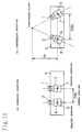
- Figure 20 shows the operating principle of the line-of-sight sensor 33 in the limbus reflection method.
- Figure 20(a) is a front view of an eyeball, and (b) is a side view of the same.
- the eyeball is illuminated with a weak infrared beam from an infrared LED, and the infrared beam reflected from the eyeball is measured with photodiodes.
- the photodiodes are directed to positions on both sides of the iris as shown by dashed lines, and the difference between the outputs of the photodiodes is calculated by an operational amplifier, to detect a horizontal movement of the eyeball.
- an infrared beam is directed to the lower part of the eyeball, as shown in Figure 20(b), and the reflected light is detected using a photodiode directed to the lower part of the iris.
- the thus obtained horizontal/vertical eyeball movement signals are converted by the line-of-sight detector 34 to a line-of-sight angle (line-of-sight signal). That is, the line of vision is measured in terms of horizontal angles, ax and ay, with respect to a predetermined reference point (the optic axis of the viewer's eyeball is directed in the direction indicated by the angles).
- the fixating point evaluator 35 calculates the position on the image display 32 on which the viewer's eye is focused.
- the fixating point evaluator 35 calculates the coordinates of the point on which the viewer's eye is rested.
- Figure 22(a) shows an example of time variation of the x component of the viewpoint F.
- the viewer's eyeballs move very quickly as the viewpoint changes from x1 to x2 to x3, and so on.
- Such eye movement is generally referred to as saccade.
- the viewer blinks his eye it is not possible to measure the viewpoint since rapid movements of the eyelid cause abrupt changes in the waveform.
- the fixating point evaluator 35 removes such transient states and detects the state (attention state) in which the viewer's eye is rested on any of the points x1 to x5. More specifically, the fixating point evaluator 35 calculates the moving speed of the viewpoint, and determines that the viewer's eye is in the fixating state (marked * in Figure 22(b)) when the moving speed is less than a prescribed value ⁇ , as shown in Figure 22(b). In the above calculation, only the x component of the viewpoint is used, but the fixating state may be detected by calculating a two-dimensional speed using both the x and y components. The time variation of the thus extracted viewer's fixating point is shown in Figure 22(c).
- positional data of the fixating point is filtered through a zero-order hold, interpolating the time where no fixating point data is available. Thereafter, the time variation of the fixating point thus detected is smoothed by a low-lass filter.
- the fixating point evaluator 35 detects the position in the displayed image on which the viewer's fixating is focused, and supplies the result as the fixating point signal to the control amount calculator 36.
- the fixating point signal is created by detecting the line-of-sight direction of one eye. Alternatively, the line-of-sight directions of both eyes may be detected, and the fixating point signal may be calculated by using the average value of these data.
- the control amount calculator 36 determines the control amount by which the parallax controller 32 controls the horizontal read timing of the left and right images. This operation will be described with reference to Figure 23.
- F designates the viewer's fixating point indicated by an fixating point signal at a given time. With this point as the center, the binocular parallaxes ⁇ x shown on the parallax map are averaged over the range of M x M pixels. The result is taken as the average binocular parallax ⁇ xave which was explained in the fourth embodiment of the invention.
- the parallax controller 31 controls the horizontal read timing of the left and right images, and moves the images horizontally.
- the control method is the same as that explained in the fourth embodiment with reference to Figure 18. That is, the right image is shifted by the average binocular parallax ⁇ xave (the horizontal read timing of the image is shifted by ⁇ xave).
- control amount calculator 36 takes the average of the binocular parallaxes within the square area having the fixating point as its center. Alternatively, their weighted average may be taken with greater weight at its center, as in the example shown in Figure 17 in the fourth embodiment.
- the line-of-sight signal is detected based only on the optic axis direction of the viewer. This method is effective when the viewer's head stays relatively still. In a freer viewing condition, a human's line of vision is given as a combined value of the direction in which the eyeball is pointed and the direction in which the head is moved.
- Methods of detecting the line of vision by combining the head and eyeball movements include a method of detecting the head of a viewer by a TV camera, and a method using a magnetic field generator in conjunction with a magnetic field detector mounted on the viewer's head, as disclosed in Japanese Patent Unexamined Publication No. 4-182226. Any of these methods may be employed.
- the binocular parallax at the position in an image that the viewer is currently viewing can be set at 0 (the image is reproduced at the position of the display screen) or at a desired value, the stereoscopic image is always formed around the image position intended by the viewer, enabling the viewer to perceive the stereoscopic depth of an object over the widest possible range.
- Figure 24 is a diagram showing the configuration of a display section in a stereoscopic image pickup and display apparatus according to a sixth embodiment of the present invention.
- Figure 24(a) shows a stereoscopic image recording section
- (b) shows a stereoscopic image display section.
- the numeral 29 is a parallax calculator
- 31 is a parallax controller
- 32 is an image display
- 36 is a control amount calculator.
- the operation of the thus constructed display section of the sixth embodiment will be described below.
- the stereoscopic image pickup camera 37 can be a conventional stereoscopic camera consisting of two ordinary video cameras mounted side by side on a universal head, or the stereoscopic image pickup section of the first embodiment of the invention. Captured images are recorded by the recorder (consisting of two conventional VTRs synchronized to each other).
- the fixating request signal is input using an ordinary pointing device, such as a mouse or tablet, and points to a given point in a captured image. This signal varies with time.
- the fixating request signal at a given time t is designated by Fix (xt, yt), where xt and yt are two-dimensional coordinate values designating the position in a captured image pointed to by the pointing device.
- This fixating request signal is recorded together with the captured image by using the recorder 38 (VTRs). More specifically, the fixating request signal is sampled at a field frequency of 60 Hz, and inserted in the video signal during each vertical retrace interval (vertical blanking period).
- the fixating request pointer 39 may be attached to an editing machine or a VTR so that the fixating request signal may be recorded when editing the recorded image.
- the thus recorded video signal and fixating request signal are processed in the stereoscopic image display section shown in Figure 24(b), and stereoscopic images are produced for display.
- the reproducer 40 (VTRs) reproduces the video signal and fixating request signal.
- the remainder of the operation is the same as that described in the fifth embodiment of the invention ( Figure 19), except that the fixating point signal is replaced by the fixating request signal output from the reproducer 40. That is, based on the parallax map calculated by the parallax calculator 29 and on the fixating request signal reproduced by the reproducer 40, the control amount calculator 36 determines the control amount by which the parallax controller 32 controls the horizontal read timing of the left and right images.
- the binocular parallaxes ⁇ x shown on the parallax map are averaged over the M x M-pixel area centered around the image position on which the fixating request signal requests the viewer to focus his fixating.
- the result is taken as the average binocular parallax ⁇ xave which was explained in the fourth embodiment of the invention.
- the parallax controller 31 controls the horizontal read timing of the left and right images, and moves the images horizontally.
- the control method is the same as that explained with reference to Figure 18. That is, the right image is shifted by the average binocular parallax ⁇ xave (the horizontal read timing of the image is shifted by ⁇ xave).
- the output of the fixating request pointer 39 may be fed directly to the control amount calculator 36 so that the viewer may input the fixating request signal while viewing the reproduced image.
- the fourth to sixth embodiment have dealt only with binocular stereoscopic images, but it will be recognized that, in a multinocular stereoscopic image display apparatus also, the same processing as described above can be applied to two images to be projected into the viewer's left and right eyes. In this case, however, since a plurality of left- and right-eye image pairs are presented for viewing at the same time, the same processing needs to be applied to each of the images.
- the stereoscopic image is always formed with a wide fusing range around the image position intended by the viewer, enabling the viewer to perceive the stereoscopic depth of an object over the widest possible range.
- Figure 25 is a diagram showing the configuration of a stereoscopic image pickup and display apparatus according to a seventh embodiment of the present invention.
- the numerals 1 and 2 are lenses
- 3a and 3b are camera bodies
- 4a and 4b are rotation controllers
- 5 is a camera spacing controller
- 14a and 14b are signal processors each for converting the camera signal into the luminance signal
- 15 is a parallax calculator for calculating horizontal parallax from left and right images
- 16 is a parallax processor for detecting the smallest parallax
- 17 is a depth display position calculator for calculating the spatial position of an object nearest to the viewer
- 18 is a fusing range verifier for verifying whether the spatial position of the object nearest to the viewer is within the fusing range of the viewer's eyes
- 19 is a converging angle controller for controlling the rotation controllers 4a, 4b so that the spatial position of the object nearest to the viewer comes within the fusing range of the viewer's eyes.
- the numeral 30 is an fixating point calculator, 31 is a parallax controller, and 32 is an image display. These components are the same as those of the display section ( Figure 16) in the stereoscopic image pickup and display apparatus of the fourth embodiment of the invention.
- both the image pickup section and the display section are controlled so that the presented stereoscopic image comes within the binocular fusing range of the viewer.
- the operation of the thus constructed stereoscopic image pickup and display apparatus of the seventh embodiment will be described below.
- control is performed so that dx in Figure 2(a) will have the largest possible value while satisfying the condition that enables all stereoscopic images to be reproduced within the fusional range.
- This operation is exactly the same as that described in the first embodiment of the invention. A brief description will be given here.
- dx is initially set to ⁇ (sufficiently large value).
- the parallax calculator 15 calculates a parallax map (a three-dimensional map showing parallax ⁇ x calculated at each coordinate position on the entire screen) from the left- and right-eye images output from the signal processors 14a and 14b.
- the parallax processor 16 Based on this parallax map, the parallax processor 16 extracts the smallest parallax (the parallax of the object reproduced nearest to the viewer) from the entire screen, and takes the result as ⁇ xmin.
- the depth display position calculator 17 calculates the depth display position Ypmin of the stereoscopic image in the stereoscopic image presentation diagram shown in Figure 5, as follows. If this Ypmin is within the binocular fusing range, the current dx value is taken as is. If [Mathematical 7] Ypmin>F(ds)min+ ⁇ F a small value ⁇ dx is added to dx.
- the fixating point calculator 30 uses the output of the parallax calculator 15, the fixating point calculator 30 obtains the average parallax or the weighted average parallax ⁇ xave for the entire screen, in accordance with which the parallax controller 31 scrolls the left and right images in such a manner as to eliminate the displacement of ⁇ xave between the left and right images.
- This processing is exactly the same as that described in the fourth embodiment of the invention.
- the converging point of the image pickup section and the displayed image position are controlled so that the stereoscopic image displayed by the image display 32 comes within the binocular fusing range of the viewer.
- stereoscopic images with wide binocular fusing range can always be presented to the viewer, and eye strain during viewing can be reduced.
- the converging angle controller 19 and parallax controller 31 are operated simultaneously.
- these two controllers may be operated in turn, or one controller may be operated after the operation of the other controller has stabilized.
- binocular parallax between images is detected, based on which the optimum converging point of the cameras is calculated that enables the viewer to perceive the stereoscopic depth of an object with the widest possible range, and the cameras are controlled so that their optic axes are directed to the converging point; further, the displayed image is automatically controlled so that the widest possible binocular fusing range can be provided for the displayed image, thereby achieving the presentation of stereoscopic images that help to reduce eye strain.
Landscapes
- Engineering & Computer Science (AREA)
- Multimedia (AREA)
- Signal Processing (AREA)
- Testing, Inspecting, Measuring Of Stereoscopic Televisions And Televisions (AREA)
Priority Applications (1)
| Application Number | Priority Date | Filing Date | Title |
|---|---|---|---|
| EP98115612A EP0888017A2 (fr) | 1993-08-26 | 1994-08-24 | Dispositif d'affichage d'image stéréoscopique et système |
Applications Claiming Priority (4)
| Application Number | Priority Date | Filing Date | Title |
|---|---|---|---|
| JP21153193 | 1993-08-26 | ||
| JP211531/93 | 1993-08-26 | ||
| JP26375393 | 1993-10-21 | ||
| JP263753/93 | 1993-10-21 |
Related Child Applications (1)
| Application Number | Title | Priority Date | Filing Date |
|---|---|---|---|
| EP98115612A Division EP0888017A2 (fr) | 1993-08-26 | 1994-08-24 | Dispositif d'affichage d'image stéréoscopique et système |
Publications (2)
| Publication Number | Publication Date |
|---|---|
| EP0641132A1 true EP0641132A1 (fr) | 1995-03-01 |
| EP0641132B1 EP0641132B1 (fr) | 1999-04-14 |
Family
ID=26518700
Family Applications (2)
| Application Number | Title | Priority Date | Filing Date |
|---|---|---|---|
| EP94113244A Expired - Lifetime EP0641132B1 (fr) | 1993-08-26 | 1994-08-24 | Appareil de prise de vues stéréoscopiques |
| EP98115612A Withdrawn EP0888017A2 (fr) | 1993-08-26 | 1994-08-24 | Dispositif d'affichage d'image stéréoscopique et système |
Family Applications After (1)
| Application Number | Title | Priority Date | Filing Date |
|---|---|---|---|
| EP98115612A Withdrawn EP0888017A2 (fr) | 1993-08-26 | 1994-08-24 | Dispositif d'affichage d'image stéréoscopique et système |
Country Status (4)
| Country | Link |
|---|---|
| US (2) | US5726704A (fr) |
| EP (2) | EP0641132B1 (fr) |
| KR (1) | KR0153214B1 (fr) |
| DE (2) | DE69417824D1 (fr) |
Cited By (23)
| Publication number | Priority date | Publication date | Assignee | Title |
|---|---|---|---|---|
| FR2735936A1 (fr) * | 1995-06-22 | 1996-12-27 | Allio Pierre | Procede d'acquisition d'images autostereoscopiques simulees |
| EP0751689A3 (fr) * | 1995-06-29 | 1997-08-06 | Matsushita Electric Industrial Co Ltd | Dispositif pour la génération d'images stéréoscopiques et ses éléments d'affichage |
| WO1998047294A1 (fr) * | 1997-04-15 | 1998-10-22 | Aea Technology Plc | Procede et dispositif servant a commander une camera |
| WO2000013423A1 (fr) * | 1998-08-28 | 2000-03-09 | Sarnoff Corporation | Procede et dispositif d'imagerie de synthese haute resolution utilisant une camera haute resolution et une camera a resolution plus faible |
| US6088006A (en) * | 1995-12-20 | 2000-07-11 | Olympus Optical Co., Ltd. | Stereoscopic image generating system for substantially matching visual range with vergence distance |
| GB2354389A (en) * | 1999-09-15 | 2001-03-21 | Sharp Kk | Stereo images with comfortable perceived depth |
| EP0921694A3 (fr) * | 1997-12-03 | 2001-03-28 | Canon Kabushiki Kaisha | Appareil de prise d'image stéréoscopique |
| WO2002013143A1 (fr) * | 2000-08-04 | 2002-02-14 | Dynamic Digital Depth Research Pty Ltd. | Procédé de conversion et de codage d'image |
| US6477267B1 (en) | 1995-12-22 | 2002-11-05 | Dynamic Digital Depth Research Pty Ltd. | Image conversion and encoding techniques |
| EP1137293A3 (fr) * | 2000-03-21 | 2005-01-05 | Olympus Corporation | Dispositif de projection d'images stéréoscopiques |
| WO2006087663A1 (fr) * | 2005-02-17 | 2006-08-24 | Koninklijke Philips Electronics N.V. | Affichage autostereoscopique |
| EP1955651A1 (fr) * | 2007-02-06 | 2008-08-13 | Siemens Schweiz AG | Dispositif de localisation spatiale d'une partie du corps mobile |
| CN102447780A (zh) * | 2010-09-08 | 2012-05-09 | Lg电子株式会社 | 移动终端及其控制方法 |
| WO2012080648A1 (fr) * | 2010-12-15 | 2012-06-21 | France Telecom | Procédé et dispositif servant à optimiser la visualisation d'images stéréoscopiques |
| CN101843107B (zh) * | 2007-10-08 | 2012-08-15 | 斯特瑞欧比亚株式会社 | Osmu(一源多用)式立体摄影机及制作其立体视频内容的方法 |
| DE102011054189A1 (de) * | 2011-10-05 | 2013-04-11 | Till Jonas | Filmaufnahmeverfahren, welches die Herstellung von räumlich wirkenden Szenerien ermöglicht |
| EP2555528A3 (fr) * | 2011-08-03 | 2013-06-19 | Sony Ericsson Mobile Communications AB | Optimisation de l'utilisation de capteurs d'image dans un environnement stéréoscopique |
| EP2574065A4 (fr) * | 2011-01-26 | 2013-12-25 | Fujifilm Corp | Dispositif de traitement d'image, dispositif de capture d'image, dispositif de reproduction et procédé de traitement d'image |
| WO2014009378A1 (fr) * | 2012-07-12 | 2014-01-16 | Essilor International (Compagnie Generale D'optique) | Génération d'image stéréoscopique |
| EP2282549A3 (fr) * | 2009-07-27 | 2014-04-02 | FUJIFILM Corporation | Appareil d'imagerie stéréoscopique et procédé d'imagerie stéréoscopique |
| WO2014130584A1 (fr) | 2013-02-19 | 2014-08-28 | Reald Inc. | Procédé et appareil d'imagerie basée sur la fixation binoculaire |
| GB2572669A (en) * | 2018-01-31 | 2019-10-09 | Synaptive Medical Barbados Inc | System for three-dimensional visualization |
| EP3644604A1 (fr) * | 2018-10-23 | 2020-04-29 | Koninklijke Philips N.V. | Appareil de génération d'image et procédé associé |
Families Citing this family (124)
| Publication number | Priority date | Publication date | Assignee | Title |
|---|---|---|---|---|
| US20060129944A1 (en) * | 1994-01-27 | 2006-06-15 | Berquist David T | Software notes |
| US6118475A (en) * | 1994-06-02 | 2000-09-12 | Canon Kabushiki Kaisha | Multi-eye image pickup apparatus, and method and apparatus for measuring or recognizing three-dimensional shape |
| US5742330A (en) * | 1994-11-03 | 1998-04-21 | Synthonics Incorporated | Methods and apparatus for the creation and transmission of 3-dimensional images |
| US6384859B1 (en) * | 1995-03-29 | 2002-05-07 | Sanyo Electric Co., Ltd. | Methods for creating an image for a three-dimensional display, for calculating depth information and for image processing using the depth information |
| GB2309847B (en) * | 1995-10-19 | 1999-09-15 | Sony Corp | Stereoscopic image generation method and apparatus thereof |
| JP3771964B2 (ja) * | 1996-03-12 | 2006-05-10 | オリンパス株式会社 | 立体映像ディスプレイ装置 |
| US6163337A (en) * | 1996-04-05 | 2000-12-19 | Matsushita Electric Industrial Co., Ltd. | Multi-view point image transmission method and multi-view point image display method |
| JPH09322199A (ja) * | 1996-05-29 | 1997-12-12 | Olympus Optical Co Ltd | 立体映像ディスプレイ装置 |
| DE69706611T2 (de) * | 1996-06-27 | 2002-07-04 | Kabushiki Kaisha Toshiba, Kawasaki | Stereoskopisches Display-System und -Verfahren |
| DE69716088T2 (de) * | 1996-12-19 | 2003-06-18 | Koninklijke Philips Electronics N.V., Eindhoven | Verfahren und gerät zur anzeige eines autostereogramms |
| JPH10276455A (ja) * | 1997-03-28 | 1998-10-13 | Sony Corp | 映像表示方法および映像表示装置 |
| JP3802653B2 (ja) * | 1997-05-21 | 2006-07-26 | オリンパス株式会社 | 立体画像表示装置 |
| JPH11113028A (ja) * | 1997-09-30 | 1999-04-23 | Toshiba Corp | 3次元映像表示装置 |
| JPH11155152A (ja) * | 1997-11-21 | 1999-06-08 | Canon Inc | 三次元形状情報入力方法及び装置及び画像入力装置 |
| JP4172554B2 (ja) * | 1998-03-12 | 2008-10-29 | 富士重工業株式会社 | ステレオカメラの調整装置 |
| US20050146521A1 (en) * | 1998-05-27 | 2005-07-07 | Kaye Michael C. | Method for creating and presenting an accurate reproduction of three-dimensional images converted from two-dimensional images |
| US6160607A (en) * | 1998-06-01 | 2000-12-12 | Diaconu; Dan Mugur | Camera focus indicator |
| JP4149037B2 (ja) * | 1998-06-04 | 2008-09-10 | オリンパス株式会社 | 映像システム |
| US6047633A (en) * | 1998-06-23 | 2000-04-11 | Khaytman; Yefim B. | Shish kebab rotisserie |
| JP2000350086A (ja) * | 1999-06-03 | 2000-12-15 | Fuji Photo Film Co Ltd | 画像処理装置、画像出力装置、及び、カメラ |
| JP2000354257A (ja) * | 1999-06-10 | 2000-12-19 | Sony Corp | 画像処理装置、画像処理方法、およびプログラム提供媒体 |
| EP1085769B1 (fr) | 1999-09-15 | 2012-02-01 | Sharp Kabushiki Kaisha | Dispositif de prise d'images stéréoscopiques |
| JP2001101415A (ja) * | 1999-09-29 | 2001-04-13 | Fujitsu Ten Ltd | 画像認識装置および画像処理装置 |
| JP3760068B2 (ja) * | 1999-12-02 | 2006-03-29 | 本田技研工業株式会社 | 画像認識装置 |
| US6788274B2 (en) * | 2000-01-31 | 2004-09-07 | National Institute Of Information And Communications Technology | Apparatus and method for displaying stereoscopic images |
| KR100908989B1 (ko) * | 2000-04-04 | 2009-07-22 | 소니 가부시끼 가이샤 | 입체 화상 작성 방법 및 그 장치 |
| JP2002027496A (ja) * | 2000-07-03 | 2002-01-25 | Canon Inc | 撮影レンズユニット、撮影装置及び撮影システム |
| KR100392381B1 (ko) * | 2000-11-13 | 2003-07-22 | 한국전자통신연구원 | 영상에서의 사물들간의 시차량을 조절하는 주시각 제어 장치 및 그 방법과 그를 이용한 평행축 입체 카메라 시스템 |
| US7277121B2 (en) * | 2001-08-29 | 2007-10-02 | Sanyo Electric Co., Ltd. | Stereoscopic image processing and display system |
| JP2003143459A (ja) * | 2001-11-02 | 2003-05-16 | Canon Inc | 複眼撮像系およびこれを備えた装置 |
| JP4148671B2 (ja) * | 2001-11-06 | 2008-09-10 | ソニー株式会社 | 表示画像制御処理装置、動画像情報送受信システム、および表示画像制御処理方法、動画像情報送受信方法、並びにコンピュータ・プログラム |
| CA2361341A1 (fr) * | 2001-11-07 | 2003-05-07 | Idelix Software Inc. | Utilisation de la presentation de detail en contexte sur des images stereoscopiques |
| ATE375687T1 (de) * | 2002-03-08 | 2007-10-15 | Topcon Corp | Vorrichtung und verfahren zur stereoskopischen bildwiedergabe |
| EP2357841B1 (fr) * | 2002-03-27 | 2015-07-22 | Sanyo Electric Co., Ltd. | Procédé et appareil de traitement d'images tridimensionnelles |
| US8369607B2 (en) * | 2002-03-27 | 2013-02-05 | Sanyo Electric Co., Ltd. | Method and apparatus for processing three-dimensional images |
| FR2838598B1 (fr) * | 2002-04-11 | 2004-10-29 | Comex Nucleaire | Procede et dispositif de television stereoscopique |
| US20040001074A1 (en) * | 2002-05-29 | 2004-01-01 | Hideki Oyaizu | Image display apparatus and method, transmitting apparatus and method, image display system, recording medium, and program |
| KR20040000144A (ko) * | 2002-06-24 | 2004-01-03 | (학)창성학원 | 스테레오 매칭을 이용한 이미지 추출방법 |
| GB0222265D0 (en) * | 2002-09-25 | 2002-10-30 | Imp College Innovations Ltd | Control of robotic manipulation |
| JP3781370B2 (ja) * | 2002-11-19 | 2006-05-31 | 本田技研工業株式会社 | 移動装置 |
| US8094927B2 (en) * | 2004-02-27 | 2012-01-10 | Eastman Kodak Company | Stereoscopic display system with flexible rendering of disparity map according to the stereoscopic fusing capability of the observer |
| US8390675B1 (en) * | 2005-10-21 | 2013-03-05 | Thomas Paul Riederer | Stereoscopic camera and system |
| JP4246691B2 (ja) * | 2004-11-30 | 2009-04-02 | 本田技研工業株式会社 | 画像情報処理システム、画像情報処理方法、画像情報処理プログラム、及び自動車 |
| EP1883242B1 (fr) * | 2005-05-20 | 2014-09-17 | Toyota Jidosha Kabushiki Kaisha | Processeur d'images pour vehicules |
| KR100667810B1 (ko) * | 2005-08-31 | 2007-01-11 | 삼성전자주식회사 | 3d 영상의 깊이감 조정 장치 및 방법 |
| JP4424299B2 (ja) * | 2005-11-02 | 2010-03-03 | ソニー株式会社 | 画像処理方法、画像処理装置およびこれを用いた画像表示装置 |
| US20160241842A1 (en) * | 2006-06-13 | 2016-08-18 | Billy D. Newbery | Digital Stereo Photographic System |
| TWI346795B (en) * | 2006-06-29 | 2011-08-11 | Himax Display Inc | Image inspecting device and method for a head-mounted display |
| FR2906899B1 (fr) * | 2006-10-05 | 2009-01-16 | Essilor Int | Dispositif d'affichage pour la visualisation stereoscopique. |
| FR2909778B1 (fr) * | 2006-12-06 | 2009-10-16 | Intersigne Soc Par Actions Sim | Procede et dispositif pour la realisation de prises de vues a l'aide d'une pluralite de capteurs optoelectroniques. |
| WO2009020277A1 (fr) * | 2007-08-06 | 2009-02-12 | Samsung Electronics Co., Ltd. | Procédé et appareil pour reproduire une image stéréoscopique par utilisation d'une commande de profondeur |
| WO2009099667A1 (fr) | 2008-02-08 | 2009-08-13 | Google Inc. | Apparel photographique panoramique équipé de multiples capteurs d'image faisant appel à des obturateurs synchronisés |
| US20090202148A1 (en) * | 2008-02-11 | 2009-08-13 | Texmag Gmbh Vertriebsgesellschaft | Image Capturing System and Method for the Analysis of Image Data |
| US9251621B2 (en) * | 2008-08-14 | 2016-02-02 | Reald Inc. | Point reposition depth mapping |
| US8300089B2 (en) * | 2008-08-14 | 2012-10-30 | Reald Inc. | Stereoscopic depth mapping |
| EP2675175A3 (fr) * | 2008-10-03 | 2014-07-23 | Real D Inc. | Mappage de profondeur optimale |
| US8334893B2 (en) * | 2008-11-07 | 2012-12-18 | Honeywell International Inc. | Method and apparatus for combining range information with an optical image |
| WO2010070536A1 (fr) * | 2008-12-19 | 2010-06-24 | Koninklijke Philips Electronics N.V. | Commande de réglages de paramètre d'affichage |
| JP5172972B2 (ja) * | 2009-01-19 | 2013-03-27 | 稔 稲葉 | 立体映像表示装置 |
| TWI573435B (zh) * | 2009-01-20 | 2017-03-01 | Inaba Minoru | Dimensional image camera display system |
| TWI632802B (zh) * | 2009-01-20 | 2018-08-11 | 稻葉稔 | 立體映像顯示裝置 |
| US8269821B2 (en) * | 2009-01-27 | 2012-09-18 | EchoStar Technologies, L.L.C. | Systems and methods for providing closed captioning in three-dimensional imagery |
| US7899321B2 (en) * | 2009-03-23 | 2011-03-01 | James Cameron | Stereo camera with automatic control of interocular distance |
| US8406619B2 (en) * | 2009-03-23 | 2013-03-26 | Vincent Pace & James Cameron | Stereo camera with automatic control of interocular distance |
| JP2010252046A (ja) * | 2009-04-15 | 2010-11-04 | Olympus Imaging Corp | 撮像装置 |
| JP5434231B2 (ja) * | 2009-04-24 | 2014-03-05 | ソニー株式会社 | 画像情報処理装置、撮像装置、画像情報処理方法およびプログラム |
| JP5409107B2 (ja) * | 2009-05-13 | 2014-02-05 | 任天堂株式会社 | 表示制御プログラム、情報処理装置、表示制御方法、および情報処理システム |
| JP2011035592A (ja) * | 2009-07-31 | 2011-02-17 | Nintendo Co Ltd | 表示制御プログラムおよび情報処理システム |
| TWI394097B (zh) * | 2009-10-12 | 2013-04-21 | Nat Univ Tsing Hua | 移動物體的偵測方法以及偵測系統 |
| US8319938B2 (en) * | 2009-10-13 | 2012-11-27 | James Cameron | Stereo camera with emulated prime lens set |
| US8090251B2 (en) * | 2009-10-13 | 2012-01-03 | James Cameron | Frame linked 2D/3D camera system |
| US7929852B1 (en) * | 2009-10-13 | 2011-04-19 | Vincent Pace | Integrated 2D/3D camera |
| JP5405264B2 (ja) | 2009-10-20 | 2014-02-05 | 任天堂株式会社 | 表示制御プログラム、ライブラリプログラム、情報処理システム、および、表示制御方法 |
| JP4754031B2 (ja) | 2009-11-04 | 2011-08-24 | 任天堂株式会社 | 表示制御プログラム、情報処理システム、および立体表示の制御に利用されるプログラム |
| US8684531B2 (en) * | 2009-12-28 | 2014-04-01 | Vision3D Technologies, Llc | Stereoscopic display device projecting parallax image and adjusting amount of parallax |
| JP2011139281A (ja) * | 2009-12-28 | 2011-07-14 | Sony Corp | 三次元画像生成装置、三次元画像表示装置、三次元画像生成方法およびプログラム |
| EP2355526A3 (fr) | 2010-01-14 | 2012-10-31 | Nintendo Co., Ltd. | Support de stockage lisible sur ordinateur doté d'un programme de contrôle de l'affichage stocké dessus, appareil de contrôle de l'affichage, système de contrôle de l'affichage et procédé de contrôle de l'affichage |
| WO2011108276A1 (fr) * | 2010-03-05 | 2011-09-09 | パナソニック株式会社 | Dispositif d'imagerie 3d et procédé d'imagerie 3d |
| US9049434B2 (en) | 2010-03-05 | 2015-06-02 | Panasonic Intellectual Property Management Co., Ltd. | 3D imaging device and 3D imaging method |
| US9188849B2 (en) | 2010-03-05 | 2015-11-17 | Panasonic Intellectual Property Management Co., Ltd. | 3D imaging device and 3D imaging method |
| US8265477B2 (en) | 2010-03-31 | 2012-09-11 | James Cameron | Stereo camera with preset modes |
| GB2479410A (en) * | 2010-04-09 | 2011-10-12 | Tektronix Uk Ltd | Measuring perceived stereoscopic visual depth |
| CN102860017B (zh) * | 2010-04-28 | 2015-06-10 | 富士胶片株式会社 | 立体摄像装置及其制造方法 |
| KR101630307B1 (ko) * | 2010-05-12 | 2016-06-14 | 삼성전자주식회사 | 디지털 촬영 장치, 그 제어 방법, 및 컴퓨터 판독가능 저장매체 |
| US9693039B2 (en) | 2010-05-27 | 2017-06-27 | Nintendo Co., Ltd. | Hand-held electronic device |
| JP5641200B2 (ja) | 2010-05-28 | 2014-12-17 | ソニー株式会社 | 画像処理装置、画像処理方法および画像処理プログラムならびに記録媒体 |
| JP5494284B2 (ja) * | 2010-06-24 | 2014-05-14 | ソニー株式会社 | 立体表示装置及び立体表示装置の制御方法 |
| US8692870B2 (en) * | 2010-06-28 | 2014-04-08 | Microsoft Corporation | Adaptive adjustment of depth cues in a stereo telepresence system |
| KR20120005328A (ko) | 2010-07-08 | 2012-01-16 | 삼성전자주식회사 | 입체 안경 및 이를 포함하는 디스플레이장치 |
| KR101645465B1 (ko) * | 2010-07-23 | 2016-08-04 | 삼성전자주식회사 | 휴대용 단말기에서 입체 영상 데이터를 생성하기 위한 장치 및 방법 |
| US8446461B2 (en) * | 2010-07-23 | 2013-05-21 | Superd Co. Ltd. | Three-dimensional (3D) display method and system |
| KR101690256B1 (ko) * | 2010-08-06 | 2016-12-27 | 삼성전자주식회사 | 영상 처리 방법 및 장치 |
| TWI436636B (zh) * | 2010-08-16 | 2014-05-01 | 宏碁股份有限公司 | 三維視訊影像調整方法及裝置 |
| WO2012037075A1 (fr) * | 2010-09-14 | 2012-03-22 | Thomson Licensing | Procédé de présentation de contenu tridimensionnel avec ajustements de disparité |
| JP2012085252A (ja) * | 2010-09-17 | 2012-04-26 | Panasonic Corp | 画像生成装置、画像生成方法、プログラムおよびプログラムを記録した記録媒体 |
| KR101723235B1 (ko) * | 2010-10-04 | 2017-04-04 | 삼성전자주식회사 | 입체 영상의 입체감을 감쇠하기 위한 장치 및 방법 |
| US8879902B2 (en) | 2010-10-08 | 2014-11-04 | Vincent Pace & James Cameron | Integrated 2D/3D camera with fixed imaging parameters |
| US9071738B2 (en) | 2010-10-08 | 2015-06-30 | Vincent Pace | Integrated broadcast and auxiliary camera system |
| JP2014501086A (ja) * | 2010-11-23 | 2014-01-16 | 深▲セン▼超多▲維▼光▲電▼子有限公司 | 立体画像取得システム及び方法 |
| JP4956664B1 (ja) * | 2010-12-14 | 2012-06-20 | 株式会社東芝 | 立体映像表示装置及び方法 |
| JP2012133232A (ja) * | 2010-12-22 | 2012-07-12 | Fujitsu Ltd | 撮影装置及び撮影制御方法 |
| CN103329549B (zh) * | 2011-01-25 | 2016-03-09 | 富士胶片株式会社 | 立体视频处理器、立体成像装置和立体视频处理方法 |
| JP2012253690A (ja) * | 2011-06-06 | 2012-12-20 | Namco Bandai Games Inc | プログラム、情報記憶媒体及び画像生成システム |
| WO2013046833A1 (fr) | 2011-09-30 | 2013-04-04 | 富士フイルム株式会社 | Dispositif d'affichage d'image, son procédé d'affichage à ajustement de disparité, et dispositif de capture d'image |
| US8619148B1 (en) * | 2012-01-04 | 2013-12-31 | Audience, Inc. | Image correction after combining images from multiple cameras |
| US8655163B2 (en) * | 2012-02-13 | 2014-02-18 | Cameron Pace Group Llc | Consolidated 2D/3D camera |
| JP6092525B2 (ja) * | 2012-05-14 | 2017-03-08 | サターン ライセンシング エルエルシーSaturn Licensing LLC | 画像処理装置、情報処理システム、画像処理方法およびプログラム |
| JP2014006674A (ja) * | 2012-06-22 | 2014-01-16 | Canon Inc | 画像処理装置及びその制御方法、プログラム |
| KR101393869B1 (ko) * | 2012-07-10 | 2014-05-12 | 엘지이노텍 주식회사 | 3d 카메라 모듈 및 그의 구동 방법 |
| US10659763B2 (en) | 2012-10-09 | 2020-05-19 | Cameron Pace Group Llc | Stereo camera system with wide and narrow interocular distance cameras |
| WO2014057618A1 (fr) | 2012-10-09 | 2014-04-17 | パナソニック株式会社 | Dispositif d'affichage tridimensionnel, dispositif de traitement d'images tridimensionnelles et procédé d'affichage tridimensionnel |
| US9300942B2 (en) | 2012-10-18 | 2016-03-29 | Industrial Technology Research Institute | Method and control system for three-dimensional video playback using visual fatigue estimation |
| JP6071422B2 (ja) * | 2012-10-29 | 2017-02-01 | 日立オートモティブシステムズ株式会社 | 画像処理装置 |
| JP2014154907A (ja) * | 2013-02-05 | 2014-08-25 | Canon Inc | 立体撮像装置 |
| US9681122B2 (en) | 2014-04-21 | 2017-06-13 | Zspace, Inc. | Modifying displayed images in the coupled zone of a stereoscopic display based on user comfort |
| JP6418784B2 (ja) * | 2014-05-20 | 2018-11-07 | キヤノン株式会社 | 画像生成装置及びその制御方法 |
| CN104634248B (zh) * | 2015-02-04 | 2017-02-22 | 西安理工大学 | 一种双目视觉下的转轴标定方法 |
| JP6703747B2 (ja) * | 2015-09-18 | 2020-06-03 | 株式会社リコー | 情報表示装置、情報提供システム、移動体装置、情報表示方法及びプログラム |
| JP6834537B2 (ja) | 2017-01-30 | 2021-02-24 | 株式会社リコー | 表示装置、移動体装置、表示装置の製造方法及び表示方法。 |
| US11582402B2 (en) * | 2018-06-07 | 2023-02-14 | Eys3D Microelectronics, Co. | Image processing device |
| CN110375709A (zh) * | 2019-05-31 | 2019-10-25 | 中国人民解放军陆军工程大学 | 一种超大视场红外双目立体视觉观察系统 |
| US11926064B2 (en) * | 2020-12-10 | 2024-03-12 | Mitsubishi Electric Corporation | Remote control manipulator system and remote control assistance system |
| TWI909057B (zh) * | 2021-06-02 | 2025-12-21 | 美商杜拜研究特許公司 | 用於表示一個三維場景及其深度平面資料之方法、編碼器及顯示裝置 |
| JP2024059439A (ja) * | 2022-10-18 | 2024-05-01 | トヨタ自動車株式会社 | 端末装置 |
Citations (4)
| Publication number | Priority date | Publication date | Assignee | Title |
|---|---|---|---|---|
| JPS60236394A (ja) * | 1984-05-10 | 1985-11-25 | Mitsubishi Heavy Ind Ltd | 立体テレビジヨン |
| EP0279092A1 (fr) * | 1987-02-18 | 1988-08-24 | Donald J. Imsand | Système de traitement d'images pour les films et les systèmes vidéos à trois dimensions |
| EP0389090A2 (fr) * | 1989-03-20 | 1990-09-26 | Tektronix Inc. | Méthode et dispositif de génération d'un modèle de vision binoculaire adapté directement à une image sélectionnée |
| US5175616A (en) * | 1989-08-04 | 1992-12-29 | Her Majesty The Queen In Right Of Canada, As Represented By The Minister Of National Defence Of Canada | Stereoscopic video-graphic coordinate specification system |
Family Cites Families (12)
| Publication number | Priority date | Publication date | Assignee | Title |
|---|---|---|---|---|
| US3636254A (en) * | 1969-11-12 | 1972-01-18 | Itek Corp | Dual-image registration system |
| US4647965A (en) * | 1983-11-02 | 1987-03-03 | Imsand Donald J | Picture processing system for three dimensional movies and video systems |
| US4819064A (en) * | 1987-11-25 | 1989-04-04 | The United States Of America As Represented By The Administrator Of The National Aeronautics And Space Administration | Television monitor field shifter and an opto-electronic method for obtaining a stereo image of optimal depth resolution and reduced depth distortion on a single screen |
| US4987487A (en) * | 1988-08-12 | 1991-01-22 | Nippon Telegraph And Telephone Corporation | Method of stereoscopic images display which compensates electronically for viewer head movement |
| US5142642A (en) * | 1988-08-24 | 1992-08-25 | Kabushiki Kaisha Toshiba | Stereoscopic television system |
| JP3129719B2 (ja) * | 1989-04-21 | 2001-01-31 | 株式会社パルカ | ビデオディスプレイ装置 |
| EP0425985B1 (fr) * | 1989-10-25 | 1997-06-11 | Hitachi, Ltd. | Système de production d'images stéréoscopiques |
| JP3104909B2 (ja) * | 1989-12-05 | 2000-10-30 | ソニー株式会社 | 画像処理装置 |
| US5142357A (en) * | 1990-10-11 | 1992-08-25 | Stereographics Corp. | Stereoscopic video camera with image sensors having variable effective position |
| US5065236A (en) * | 1990-11-02 | 1991-11-12 | The United States Of America As Represented By The Administrator Of The National Aeronautics And Space Administration | Stereoscopic camera and viewing systems with undistorted depth presentation and reduced or eliminated erroneous acceleration and deceleration perceptions, or with perceptions produced or enhanced for special effects |
| JPH04182226A (ja) * | 1990-11-19 | 1992-06-29 | Mita Ind Co Ltd | 外光侵入防止構造 |
| JP3347385B2 (ja) * | 1992-03-27 | 2002-11-20 | オリンパス光学工業株式会社 | 内視鏡画像処理装置 |
-
1994
- 1994-08-24 EP EP94113244A patent/EP0641132B1/fr not_active Expired - Lifetime
- 1994-08-24 EP EP98115612A patent/EP0888017A2/fr not_active Withdrawn
- 1994-08-24 DE DE69417824A patent/DE69417824D1/de not_active Expired - Fee Related
- 1994-08-24 DE DE69417824T patent/DE69417824T4/de not_active Expired - Lifetime
- 1994-08-25 KR KR1019940021006A patent/KR0153214B1/ko not_active Expired - Fee Related
-
1996
- 1996-01-22 US US08/589,374 patent/US5726704A/en not_active Expired - Fee Related
-
1997
- 1997-03-31 US US08/832,603 patent/US5801760A/en not_active Expired - Fee Related
Patent Citations (4)
| Publication number | Priority date | Publication date | Assignee | Title |
|---|---|---|---|---|
| JPS60236394A (ja) * | 1984-05-10 | 1985-11-25 | Mitsubishi Heavy Ind Ltd | 立体テレビジヨン |
| EP0279092A1 (fr) * | 1987-02-18 | 1988-08-24 | Donald J. Imsand | Système de traitement d'images pour les films et les systèmes vidéos à trois dimensions |
| EP0389090A2 (fr) * | 1989-03-20 | 1990-09-26 | Tektronix Inc. | Méthode et dispositif de génération d'un modèle de vision binoculaire adapté directement à une image sélectionnée |
| US5175616A (en) * | 1989-08-04 | 1992-12-29 | Her Majesty The Queen In Right Of Canada, As Represented By The Minister Of National Defence Of Canada | Stereoscopic video-graphic coordinate specification system |
Non-Patent Citations (2)
| Title |
|---|
| BERND KOST: "Konstruktion von Zwischenansichten für Multi-Viewpoint-3DTV-Systeme", FERNSEH & KINO TECHNIK, vol. 42, no. 2, February 1988 (1988-02-01), HEIDELBERG (DE), pages 67 - 73, XP000858537 * |
| PATENT ABSTRACTS OF JAPAN vol. 10, no. 95 (E - 395)<2152> 12 April 1986 (1986-04-12) * |
Cited By (48)
| Publication number | Priority date | Publication date | Assignee | Title |
|---|---|---|---|---|
| WO1997001250A1 (fr) * | 1995-06-22 | 1997-01-09 | Pierre Allio | Procede et systeme d'acquisition d'images autostereoscopiques |
| FR2735936A1 (fr) * | 1995-06-22 | 1996-12-27 | Allio Pierre | Procede d'acquisition d'images autostereoscopiques simulees |
| US6262743B1 (en) | 1995-06-22 | 2001-07-17 | Pierre Allio | Autostereoscopic image acquisition method and system |
| US6268880B1 (en) | 1995-06-29 | 2001-07-31 | Matsushita Electric Industrial Co., Ltd. | Stereoscopic CG image generating apparatus and stereoscopic TV apparatus |
| EP0751689A3 (fr) * | 1995-06-29 | 1997-08-06 | Matsushita Electric Industrial Co Ltd | Dispositif pour la génération d'images stéréoscopiques et ses éléments d'affichage |
| US6005607A (en) * | 1995-06-29 | 1999-12-21 | Matsushita Electric Industrial Co., Ltd. | Stereoscopic computer graphics image generating apparatus and stereoscopic TV apparatus |
| EP1328129A1 (fr) * | 1995-06-29 | 2003-07-16 | Matsushita Electric Industrial Co., Ltd. | Dispositif pour la génération par ordinateur des images stéréoscopiques |
| US6417880B1 (en) | 1995-06-29 | 2002-07-09 | Matsushita Electric Industrial Co., Ltd. | Stereoscopic CG image generating apparatus and stereoscopic TV apparatus |
| US6175379B1 (en) | 1995-06-29 | 2001-01-16 | Matsushita Electric Industrial Co., Ltd. | Stereoscopic CG image generating apparatus and stereoscopic TV apparatus |
| US6353457B2 (en) | 1995-06-29 | 2002-03-05 | Matsushita Electric Industrial Co., Ltd. | Stereoscopic computer graphics image generating apparatus and stereoscopic TV apparatus |
| EP1168852A1 (fr) * | 1995-06-29 | 2002-01-02 | Matsushita Electric Industrial Co., Ltd. | Dispositif pour la génération par ordinateur des images stéréoscopiques |
| US6088006A (en) * | 1995-12-20 | 2000-07-11 | Olympus Optical Co., Ltd. | Stereoscopic image generating system for substantially matching visual range with vergence distance |
| US6477267B1 (en) | 1995-12-22 | 2002-11-05 | Dynamic Digital Depth Research Pty Ltd. | Image conversion and encoding techniques |
| WO1998047294A1 (fr) * | 1997-04-15 | 1998-10-22 | Aea Technology Plc | Procede et dispositif servant a commander une camera |
| EP0921694A3 (fr) * | 1997-12-03 | 2001-03-28 | Canon Kabushiki Kaisha | Appareil de prise d'image stéréoscopique |
| US6762794B1 (en) | 1997-12-03 | 2004-07-13 | Canon Kabushiki Kaisha | Image pick-up apparatus for stereoscope |
| WO2000013423A1 (fr) * | 1998-08-28 | 2000-03-09 | Sarnoff Corporation | Procede et dispositif d'imagerie de synthese haute resolution utilisant une camera haute resolution et une camera a resolution plus faible |
| GB2354389A (en) * | 1999-09-15 | 2001-03-21 | Sharp Kk | Stereo images with comfortable perceived depth |
| US6798406B1 (en) | 1999-09-15 | 2004-09-28 | Sharp Kabushiki Kaisha | Stereo images with comfortable perceived depth |
| EP1137293A3 (fr) * | 2000-03-21 | 2005-01-05 | Olympus Corporation | Dispositif de projection d'images stéréoscopiques |
| WO2002013143A1 (fr) * | 2000-08-04 | 2002-02-14 | Dynamic Digital Depth Research Pty Ltd. | Procédé de conversion et de codage d'image |
| WO2006087663A1 (fr) * | 2005-02-17 | 2006-08-24 | Koninklijke Philips Electronics N.V. | Affichage autostereoscopique |
| US8427527B2 (en) | 2005-02-17 | 2013-04-23 | Koninklijke Philips Electronics N.V. | Autostereoscopic display |
| EP1955651A1 (fr) * | 2007-02-06 | 2008-08-13 | Siemens Schweiz AG | Dispositif de localisation spatiale d'une partie du corps mobile |
| WO2008095686A1 (fr) * | 2007-02-06 | 2008-08-14 | Siemens Schweiz Ag | Dispositif pour la localisation spatiale d'une partie corporelle mobile |
| CN101843107B (zh) * | 2007-10-08 | 2012-08-15 | 斯特瑞欧比亚株式会社 | Osmu(一源多用)式立体摄影机及制作其立体视频内容的方法 |
| EP2282549A3 (fr) * | 2009-07-27 | 2014-04-02 | FUJIFILM Corporation | Appareil d'imagerie stéréoscopique et procédé d'imagerie stéréoscopique |
| CN102447780A (zh) * | 2010-09-08 | 2012-05-09 | Lg电子株式会社 | 移动终端及其控制方法 |
| EP2429198A3 (fr) * | 2010-09-08 | 2012-10-17 | Lg Electronics Inc. | Appareil mobile et son procédé de contrôle |
| US8842167B2 (en) | 2010-09-08 | 2014-09-23 | Lg Electronics Inc. | Mobile terminal and controlling method thereof |
| FR2969457A1 (fr) * | 2010-12-15 | 2012-06-22 | France Telecom | Procede et dispositif d'evaluation d'une chaine de production et de visualisation d'images stereoscopiques |
| WO2012080648A1 (fr) * | 2010-12-15 | 2012-06-21 | France Telecom | Procédé et dispositif servant à optimiser la visualisation d'images stéréoscopiques |
| EP2574065A4 (fr) * | 2011-01-26 | 2013-12-25 | Fujifilm Corp | Dispositif de traitement d'image, dispositif de capture d'image, dispositif de reproduction et procédé de traitement d'image |
| EP2555528A3 (fr) * | 2011-08-03 | 2013-06-19 | Sony Ericsson Mobile Communications AB | Optimisation de l'utilisation de capteurs d'image dans un environnement stéréoscopique |
| US9883164B2 (en) | 2011-08-03 | 2018-01-30 | Sony Mobile Communications Inc. | Optimizing usage of image sensors in a stereoscopic environment |
| DE102011054189A1 (de) * | 2011-10-05 | 2013-04-11 | Till Jonas | Filmaufnahmeverfahren, welches die Herstellung von räumlich wirkenden Szenerien ermöglicht |
| WO2013050514A1 (fr) | 2011-10-05 | 2013-04-11 | Jonas Till | Procédé d'enregistrement de films permettant la production de scènes actives dans l'espace |
| WO2014009378A1 (fr) * | 2012-07-12 | 2014-01-16 | Essilor International (Compagnie Generale D'optique) | Génération d'image stéréoscopique |
| EP2959685A4 (fr) * | 2013-02-19 | 2016-08-24 | Reald Inc | Procédé et appareil d'imagerie basée sur la fixation binoculaire |
| WO2014130584A1 (fr) | 2013-02-19 | 2014-08-28 | Reald Inc. | Procédé et appareil d'imagerie basée sur la fixation binoculaire |
| US10129538B2 (en) | 2013-02-19 | 2018-11-13 | Reald Inc. | Method and apparatus for displaying and varying binocular image content |
| GB2572669A (en) * | 2018-01-31 | 2019-10-09 | Synaptive Medical Barbados Inc | System for three-dimensional visualization |
| GB2572669B (en) * | 2018-01-31 | 2022-11-02 | Synaptive Medical Inc | System for three-dimensional visualization |
| EP3644604A1 (fr) * | 2018-10-23 | 2020-04-29 | Koninklijke Philips N.V. | Appareil de génération d'image et procédé associé |
| WO2020083950A1 (fr) * | 2018-10-23 | 2020-04-30 | Koninklijke Philips N.V. | Appareil de génération d'image et procédé associé |
| CN112913230A (zh) * | 2018-10-23 | 2021-06-04 | 皇家飞利浦有限公司 | 图像生成装置及其方法 |
| KR20210076975A (ko) * | 2018-10-23 | 2021-06-24 | 코닌클리케 필립스 엔.브이. | 이미지 생성 장치 및 그를 위한 방법 |
| CN112913230B (zh) * | 2018-10-23 | 2023-09-12 | 皇家飞利浦有限公司 | 图像生成装置及其方法 |
Also Published As
| Publication number | Publication date |
|---|---|
| DE69417824D1 (de) | 1999-05-20 |
| EP0641132B1 (fr) | 1999-04-14 |
| KR0153214B1 (ko) | 1998-11-16 |
| DE69417824T2 (de) | 1999-08-12 |
| EP0888017A2 (fr) | 1998-12-30 |
| US5726704A (en) | 1998-03-10 |
| DE69417824T4 (de) | 2000-06-29 |
| US5801760A (en) | 1998-09-01 |
| KR950007577A (ko) | 1995-03-21 |
Similar Documents
| Publication | Publication Date | Title |
|---|---|---|
| US5726704A (en) | Stereoscopic image pickup and display apparatus | |
| JP3089306B2 (ja) | 立体画像撮像及び表示装置 | |
| US6198484B1 (en) | Stereoscopic display system | |
| US6005607A (en) | Stereoscopic computer graphics image generating apparatus and stereoscopic TV apparatus | |
| US8456518B2 (en) | Stereoscopic camera with automatic obstruction removal | |
| EP0921694B1 (fr) | Appareil de prise d'image stéréoscopique | |
| KR100519864B1 (ko) | 화상정보입력장치및그방법 | |
| JP3771973B2 (ja) | 立体映像表示装置 | |
| JP6020923B2 (ja) | 焦点可変レンズを有するビューア、および映像表示システム | |
| US6788274B2 (en) | Apparatus and method for displaying stereoscopic images | |
| WO2012021967A1 (fr) | Système et procédé pour analyser un contenu multimédia tridimensionnel (3d) | |
| JPH06235885A (ja) | 立体映像表示装置 | |
| JP2002223458A (ja) | 立体映像作成装置 | |
| KR101270025B1 (ko) | 스테레오 카메라의 주시각 제어방법 및 그 스테레오 카메라 장치 | |
| US12393027B2 (en) | Head-mountable display apparatus and methods | |
| JP2012244453A (ja) | 画像表示装置、画像表示システム、及び3次元眼鏡 | |
| JP2015094831A (ja) | 立体撮像装置およびその制御方法、制御プログラム | |
| KR100392381B1 (ko) | 영상에서의 사물들간의 시차량을 조절하는 주시각 제어 장치 및 그 방법과 그를 이용한 평행축 입체 카메라 시스템 | |
| JP3425402B2 (ja) | 立体画像を表示する装置および方法 | |
| JP5331785B2 (ja) | 立体画像分析装置 | |
| JPH08223609A (ja) | 焦点調節の可能な三次元表示方法および表示装置 | |
| JP4235291B2 (ja) | 立体映像システム | |
| JPH11168755A (ja) | 立体映像撮像装置 | |
| JPH06268942A (ja) | 立体提示装置 |
Legal Events
| Date | Code | Title | Description |
|---|---|---|---|
| PUAI | Public reference made under article 153(3) epc to a published international application that has entered the european phase |
Free format text: ORIGINAL CODE: 0009012 |
|
| AK | Designated contracting states |
Kind code of ref document: A1 Designated state(s): DE FR GB NL |
|
| 17P | Request for examination filed |
Effective date: 19950803 |
|
| 17Q | First examination report despatched |
Effective date: 19970714 |
|
| GRAG | Despatch of communication of intention to grant |
Free format text: ORIGINAL CODE: EPIDOS AGRA |
|
| GRAG | Despatch of communication of intention to grant |
Free format text: ORIGINAL CODE: EPIDOS AGRA |
|
| GRAH | Despatch of communication of intention to grant a patent |
Free format text: ORIGINAL CODE: EPIDOS IGRA |
|
| GRAH | Despatch of communication of intention to grant a patent |
Free format text: ORIGINAL CODE: EPIDOS IGRA |
|
| GRAA | (expected) grant |
Free format text: ORIGINAL CODE: 0009210 |
|
| AK | Designated contracting states |
Kind code of ref document: B1 Designated state(s): DE FR GB NL |
|
| REF | Corresponds to: |
Ref document number: 69417824 Country of ref document: DE Date of ref document: 19990520 |
|
| ET | Fr: translation filed | ||
| PLBE | No opposition filed within time limit |
Free format text: ORIGINAL CODE: 0009261 |
|
| STAA | Information on the status of an ep patent application or granted ep patent |
Free format text: STATUS: NO OPPOSITION FILED WITHIN TIME LIMIT |
|
| 26N | No opposition filed | ||
| REG | Reference to a national code |
Ref country code: GB Ref legal event code: IF02 |
|
| PGFP | Annual fee paid to national office [announced via postgrant information from national office to epo] |
Ref country code: FR Payment date: 20050809 Year of fee payment: 12 |
|
| PGFP | Annual fee paid to national office [announced via postgrant information from national office to epo] |
Ref country code: NL Payment date: 20050815 Year of fee payment: 12 |
|
| PGFP | Annual fee paid to national office [announced via postgrant information from national office to epo] |
Ref country code: DE Payment date: 20050818 Year of fee payment: 12 |
|
| PGFP | Annual fee paid to national office [announced via postgrant information from national office to epo] |
Ref country code: GB Payment date: 20050824 Year of fee payment: 12 |
|
| PG25 | Lapsed in a contracting state [announced via postgrant information from national office to epo] |
Ref country code: NL Free format text: LAPSE BECAUSE OF NON-PAYMENT OF DUE FEES Effective date: 20070301 Ref country code: DE Free format text: LAPSE BECAUSE OF NON-PAYMENT OF DUE FEES Effective date: 20070301 |
|
| GBPC | Gb: european patent ceased through non-payment of renewal fee |
Effective date: 20060824 |
|
| NLV4 | Nl: lapsed or anulled due to non-payment of the annual fee |
Effective date: 20070301 |
|
| REG | Reference to a national code |
Ref country code: FR Ref legal event code: ST Effective date: 20070430 |
|
| PG25 | Lapsed in a contracting state [announced via postgrant information from national office to epo] |
Ref country code: GB Free format text: LAPSE BECAUSE OF NON-PAYMENT OF DUE FEES Effective date: 20060824 |
|
| PG25 | Lapsed in a contracting state [announced via postgrant information from national office to epo] |
Ref country code: FR Free format text: LAPSE BECAUSE OF NON-PAYMENT OF DUE FEES Effective date: 20060831 |