EP0642230A1 - Systeme de communication vocale - Google Patents
Systeme de communication vocale Download PDFInfo
- Publication number
- EP0642230A1 EP0642230A1 EP94904008A EP94904008A EP0642230A1 EP 0642230 A1 EP0642230 A1 EP 0642230A1 EP 94904008 A EP94904008 A EP 94904008A EP 94904008 A EP94904008 A EP 94904008A EP 0642230 A1 EP0642230 A1 EP 0642230A1
- Authority
- EP
- European Patent Office
- Prior art keywords
- speech
- signal
- echo
- amplitude
- communication apparatus
- Prior art date
- Legal status (The legal status is an assumption and is not a legal conclusion. Google has not performed a legal analysis and makes no representation as to the accuracy of the status listed.)
- Withdrawn
Links
Images


Classifications
-
- H—ELECTRICITY
- H04—ELECTRIC COMMUNICATION TECHNIQUE
- H04B—TRANSMISSION
- H04B3/00—Line transmission systems
- H04B3/02—Details
- H04B3/20—Reducing echo effects or singing; Opening or closing transmitting path; Conditioning for transmission in one direction or the other
- H04B3/23—Reducing echo effects or singing; Opening or closing transmitting path; Conditioning for transmission in one direction or the other using a replica of transmitted signal in the time domain, e.g. echo cancellers
-
- H—ELECTRICITY
- H04—ELECTRIC COMMUNICATION TECHNIQUE
- H04M—TELEPHONIC COMMUNICATION
- H04M9/00—Arrangements for interconnection not involving centralised switching
- H04M9/08—Two-way loud-speaking telephone systems with means for conditioning the signal, e.g. for suppressing echoes for one or both directions of traffic
- H04M9/082—Two-way loud-speaking telephone systems with means for conditioning the signal, e.g. for suppressing echoes for one or both directions of traffic using echo cancellers
Definitions
- the present invention relates to a speech communication apparatus having an echo canceler for canceling acoustic echoes generated during hands-free speech as in a mobile telephone apparatus.
- an apparatus has a hands-free speech mode in addition to a handset talking mode.
- the hands-free speech mode is a mode in which a receiving speech loudspeaker and a transmitting speech microphone are arranged in a telephone apparatus body or a dashboard independently of a handset, and the loudspeaker and the microphone constitute a handset to perform talking.
- a speaker can speak without holding a handset. The speaker can safely speak without having to hold the steering wheel with a single hand even during driving.
- the hands-free speech mode is very useful to improve safety during driving.
- an echo canceler for canceling the above echo signal is generally arranged in a telephone apparatus having such a hands-free speech mode.
- the echo canceler is inevitably used because signal delays caused by a speech encoding/decoding circuit (speech codec) and an error correction encoding/decoding circuit (channel codec) are large so that the acoustic echoes bother the speaker.
- a conventional acoustic echo canceler comprises a digital signal processor.
- This processor comprises arithmetic operation means for simulating acoustic characteristics of an echo path from the loudspeaker to the microphone, subtracting means for obtaining a difference between an output from the arithmetic operation means and an input from the microphone, and means for changing the acoustic characteristics of the arithmetic operation means such that the output from the subtracter becomes zero.
- a speech signal supplied to the loudspeaker is supplied to the arithmetic operation means to generate a pseudo acoustic echo, and this pseudo acoustic echo is subtracted from an actual transmitting speech signal (containing the acoustic echo) transmitted from the microphone, thereby canceling the acoustic echo.
- An output from the subtracter is deviated from zero in accordance with a change in acoustic characteristics of the echo path.
- the coefficient of the arithmetic operation means is changed such that the output from the subtracter becomes zero, the acoustic echo signal can always be canceled.
- a volume control is inserted in the receiving speech signal path of the speech communication apparatus.
- a speaker operates this volume control to adjust the receiving speech volume.
- the receiving speech volume is set excessively high upon operation of the volume control, the signal level of a receiving speech signal exceeds the dynamic ranges of a receiving speech amplifier and a loudspeaker, thereby distorting received speech.
- the received speech produced from the loudspeaker is distorted, an echo signal having distortion corresponding to the distortion of the received speech is also input to the microphone. As a result, the echo canceler cannot sufficiently cancel the echo signal.
- the receiving speech signal level may be temporarily increased due to a small loss of the wired line of the partner or a change in loudness of the partner's voice. In this case, the received speech is distorted, and the distorted echo may not be canceled.
- the above description have exemplified the hands-free speech mode.
- speech received from the receiver may be input to the microphone, and an acoustic echo signal may be generated. That is, the above problem is not limited to the hands-free speech mode.
- the above problem is not limited to a mobile telephone apparatus, but is equally applicable to a wired telephone apparatus, a radio communication machine, and a transceiver, and the like.
- the present invention has been made in consideration of the above situation, and has as its object to cause an echo canceler to sufficiently cancel an acoustic echo even if the signal level of a receiving speech signal exceeds the dynamic ranges of a receiving speech amplifier and a loudspeaker in a speech communication apparatus having the echo canceler for canceling an acoustic echo contained in a transmitted signal by estimating an echo path of the received signal, thereby further improving talking quality.
- a speech communication apparatus characterized by comprising transceiver means for transmitting and receiving speech, loudspeaker means for outputting the speech received by the transceiver means, microphone means for inputting transmitted speech, means, connected between the loudspeaker means and the transceiver means and between the microphone means and the transceiver means, for canceling an acoustic echo generated upon inputting the received speech output from the loudspeaker means to the microphone means, and means for limiting, to a predetermined value, an amplitude of a receiving speech signal input to the echo canceling means, the amplitude being the predetermined value or more.
- a speech communication apparatus in which means for adjusting a volume of the receiving speech signal is connected to an output side of the amplitude limiting means, wherein a decrease/increase in amplitude limit level is performed by the amplitude limiting means in association with an increase/decrease of a volume of the amplitude limiting means.
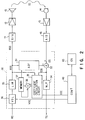
- FIG. 1 is a circuit block diagram showing the arrangement of a dual mode radio telephone apparatus according to the first embodiment of the speech communication apparatus of the present invention.
- a dual mode is defined as a scheme for selectively using an analog mode and a digital mode.
- the analog mode is defined as a scheme in which a transmitter apparatus, e.g., FM-modulates a carrier with an analog speech signal and data, and transmits the speech signal and data, and a receiver apparatus receives the modulated carrier sent from the transmitter apparatus and FM-demodulates the received signal and data to reproduce the analog speech signal and data.
- the digital mode is defined as a scheme in which a transmitter apparatus encodes a speech signal and data, digitally modulates a carrier with the encoded signal in accordance with, e.g., a ⁇ /4 shifted DQPSK ( ⁇ /4 shifted, differentially encoded quadrature phase shift keying) scheme, and transmits the digitally modulated wave, and a receiving apparatus receives the modulated wave sent from the transmitter apparatus, digitally demodulates the digitally modulated wave, and decodes the demodulated signal, thereby reproducing the speech signal and data.
- a transmitter apparatus encodes a speech signal and data
- digitally modulates a carrier with the encoded signal in accordance with, e.g., a ⁇ /4 shifted DQPSK ( ⁇ /4 shifted, differentially encoded quadrature phase shift keying) scheme
- a receiving apparatus receives the modulated wave sent from the transmitter apparatus, digitally demodulates the digitally modulated wave, and decodes the demodulated signal, thereby reproducing the speech signal and
- a radio frequency signal sent from a base station (not shown) through a digital or analog talking channel is received by an antenna 1 and input to a reception circuit (RX) 3 through an antenna duplexer (DUP) 2.
- the antenna 1 can be used as either a reception or transmission antenna.
- the antenna 1 is switched by the duplexer 2 and serves either the reception or transmission antenna.
- the radio frequency signal is mixed with a reception local oscillation signal output from a frequency synthesizer (SYN) 4 to frequency-modulate it into an intermediate frequency signal.
- the frequency of the reception local oscillation signal generated by the frequency synthesizer 4 is controlled by a control signal SYC output from a control circuit 40.
- the reception circuit 3 converts the intermediate frequency signal into a digital signal through an A/D converter 6, and the digital signal is supplied to a digital demodulator (DEM) 7.
- the reception circuit 3 supplies the intermediate frequency signal to an analog audio circuit (ANALOG AUDIO) 20.
- the received intermediate frequency signal is converted into a digital baseband signal.
- the digital baseband signal output from the digital demodulator 7 contains the digital receiving speech signal and the digital control signal.
- the digital receiving speech signal is input to an error correction encoding/decoding circuit (CH-COD) 8.
- the error correction encoding/decoding circuit 8 performs error correction decoding of the digital receiving speech signal supplied from the digital demodulator 6, so that an error-corrected digital receiving speech signal is input to a speech encoding/decoding circuit (SP-COD) 9.
- a digital control signal DCS is input from the digital demodulator 7 and the error correction demodulator 8 to the control circuit 20 and is identified.
- the speech encoding/decoding circuit 9 performs the speech decoding process of the digital receiving speech signal.
- a digital receiving speech signal RS output from the speech encoding/decoding circuit 9 is input to an echo canceler (EC-CAN) 30 through a switching circuit 10.
- the received intermediate frequency signal input to the analog audio circuit 20 is FM-modulated, and the speech level of the FM-modulated signal is amplified.
- An analog baseband talking signal output from the analog speech circuit 20 is temporarily converted into a digital signal by an A/D converter 21.
- the converted signal is input to the echo canceler 30 as the digital receiving speech signal RS.
- Part of the digital receiving speech signal RS is received by the echo canceler 30.
- a digital receiving speech signal output from an echo canceler is converted into an analog receiving speech signal by a D/A converter 11, the converted signal is amplified by a receiving speech amplifier 12, and the amplified signal is supplied to a loudspeaker 13, thereby producing amplified speech from the loudspeaker 13.
- a speaker's transmitting speech signal input to a microphone 14 is amplified by a transmitting speech amplifier 15, and the amplified signal is converted into a digital transmitting speech signal by an A/D converter 16.
- the digital signal is then input to the echo canceler 30.
- the echo canceler 30 performs a process for canceling an acoustic echo contained in the digital transmitting speech signal. The details of the process will be described later with reference to FIG. 2.
- a digital transmitting speech signal TS output from the echo canceler 30 is input to the speech encoding/decoding circuit 9 through a switching circuit 17 if the transmitting speech channel is a digital channel.
- a transmitting speech signal is input to the analog audio circuit 20 through a D/A converter 22 and the switching circuit 17.
- the speech encoding/decoding circuit 9 performs the speech encoding process of the digital transmitting speech signal.
- a digital transmitting speech signal output from the speech encoding/decoding circuit 9 is input to the error correction decoding circuit 8 together with the digital control signal output from the control circuit 40.
- the error correction encoding/decoding circuit 8 performs the error correction encoding process of the digital transmitting speech signal and the digital control signal.
- the coded digital transmitting speech signal is input to a digital modulator (MOD) 18.
- MOD digital modulator
- a signal modulated by ⁇ /4 shifted DQPSK in accordance with the digital transmitting speech signal is generated, and the modulated signal is converted into an analog signal by a D/A converter 19.
- the resultant analog signal is input to a transmission circuit (TX) 5.
- an FM-modulated signal corresponding to the transmitting speech signal is generated and is input to the transmission circuit 5.
- the input modulated signal is mixed with the transmission local oscillation circuit corresponding to a talking channel radio frequency generated by the frequency synthesizer 4 and is converted into a radio transmission signal.
- the radio transmission signal is also RF-amplified.
- a radio transmission signal output from the transmission circuit 5 is supplied to the antenna 1 through the antenna duplexer 2 and is transmitted from the antenna 1 to a base station (not shown).
- the switching operations of the switching circuits 10 and 17 are controlled by a switching control signal SWC output from the control circuit 40.
- the switching control signal is switched in accordance with the digital or analog mode.
- the control circuit 40 has, e.g., a microcomputer serving as a main controller.
- the control circuit is connected to a console unit (CU) 43.
- the console unit 43 includes key switches and a display.
- the display comprises, e.g., a liquid crystal display.
- the key switches comprise a transmission key, an end key, a dial key, a mode designation key, and a volume control key.
- the mode designation key is used to allow a user to selectively input and designate the analog mode, the digital mode, or a dual mode which does not designate any mode.
- the volume control key is used to allow the user to adjust the receiving speech volume.
- a power supply circuit 42 generates a desired operation voltage Vcc on the basis of an output from a battery 41 and applies the voltage Vcc to each circuit.
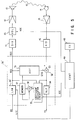
- FIG. 2 is a circuit block diagram showing its arrangement together with peripheral circuits.
- the echo canceler 30 is constituted by, e.g., a DSP (Digital signal processor).
- the DSP is functionally divided into an adaptive filter (ADF) 31, a subtracter 32, a coefficient calculation circuit 33 for calculating the coefficient of the filter 31, a coefficient storage memory 37, a coefficient updating subtracter 38, a nonlinear circuit (NLP) 34, an amplitude limiter (LIM) 35, and a volume control (VOL) 36.
- ADF adaptive filter
- NLP nonlinear circuit
- LIM amplitude limiter
- VOL volume control
- the receiving speech signal RS is supplied to the amplitude limiter 35 through the volume control 36.
- the volume control 36 changes the level of the receiving speech signal RS by a level corresponding to a volume control signal VOC output from the control circuit 40 in accordance with a volume designation signal from the console unit 43.
- the amplitude limiter 35 limits the amplitude level of the receiving speech signal RS to a predetermined amplitude. That is, an amplitude having a value exceeding the predetermined value is limited to the predetermined value. This amplitude limit level value is set such that the amplitude level of the receiving speech signal does not exceed the dynamic ranges of the receiving speech amplifier 12 and the loudspeaker 13.
- An output RSS from the amplitude limiter 35 is supplied to the adaptive filter 31 and the D/A converter 11.
- An acoustic echo signal ES generated when a receiving speech signal output from the loudspeaker 13 is input to the microphone 14 is input to the echo canceler 30 and is supplied to the positive input terminal of the subtracter 32.
- the adaptive filter 31 simulates the acoustic characteristics of an echo path from the loudspeaker to the microphone to generate a pseudo echo signal ESS.
- the pseudo echo signal ESS is supplied to the negative input terminal of the subtracter 32.
- the pseudo echo signal ESS may be supplied to the positive input terminal of the subtracter 32 and the acoustic echo signal ES may be supplied to the negative input terminal of the subtracter 32.
- FIG. 3 is a detailed functional block diagram of the adaptive filter 31.
- An input speech signal x(n) and output signals x(n-1), x(n-2),..., x(n-M) from the delay circuits are supplied to an adder 56 through amplifiers 540, 541, ..., 54 M .
- Amplification coefficients h0, h1, ..., h M of the amplifiers 540, 541, ..., 54 M are supplied from the coefficient memory 37. These coefficients h0, h1, ..., h M are changed to allow a change in acoustic characteristics of an echo path to be simulated.
- the output RSS from the amplitude limiter 35 and an output (residual signal) from the subtracter 32 are supplied to the coefficient calculation circuit 33.
- the coefficient calculation circuit 33 adaptively changes the coefficients for calculating the pseudo echo signal in such a manner that the residual signal is always set to zero. By this adaptive operation, the acoustic characteristics of a space to be used, i.e., an echo path are estimated.
- the pseudo echo signal EES is generated on the basis of this estimation result and the receiving speech signal RSS.
- the subtracter 32 performs an arithmetic operation process to subtract the pseudo echo signal EES from the echo signal ES, thereby canceling the echo signal ES.
- the coefficients calculated by the coefficient calculation circuit 33 are supplied to the positive input terminal of the subtracter 38.
- the outputs from the subtracter 38 are written in the coefficient memory 37.
- Outputs from the memory 37 are supplied to the amplifiers 540, 541, ..., 54 M in the adaptive filter 31 as the amplification coefficients h0, h1, ..., h M and at the same time supplied to the negative input terminal of the subtracter 38.
- the coefficient calculation circuit 33 determines a specific decrease in magnitude (amplitude) of each timing signal for the receiving speech signal RSS on the basis of the remaining echo level of each timing (time) signal from the corresponding residual signal. The coefficient calculation circuit 33 then determines the coefficients h0, h1, ..., h M on the basis of this determination result. Therefore, the coefficients fall within the range of the values from 0 to 1. After the coefficients are stored in the memory 37, they are supplied to the adaptive filter 31. For example, if a coefficient h i stored at a given timing "i" is 0.5, and the calculation circuit 33 outputs a coefficient of 0.3 at the next timing, the subtracter 38 obtains a difference of -0.2. The coefficient in the memory 37 is decreased by 0.2, and the coefficient is updated to 0.3. When the echo is completely canceled, the coefficient need not be changed, and the operation circuit 33 outputs the same coefficient as that at the previous timing.
- the coefficient memory 37 stores hands-free speech mode coefficients and handset talking mode coefficients independently of each other.
- a talking mode is set using the console unit 43.
- the coefficients used immediately preceding switching are set in the memory 37.
- the coefficients stored in the memory 37 are read out and supplied to the adaptive filter 31.
- the nonlinear circuit 34 forcibly nullifies a residual signal having a predetermined level or less and passing through the subtracter 32.
- FIG. 4 is a graph showing the input/output characteristics of a circuit portion integrating the volume control 36 and the amplitude limiter 35.
- the amplitude limiter 35 limits the output level to a predetermined value. This predetermined value has a saturation level or less of the receiving speech amplifier 12.
- the volume control 36 is connected to the input of the amplitude limiter 35. Therefore, even if the level of the receiving speech signal RS is changed by the volume control 36 to perform volume control, as indicated by broken lines in FIG. 4, a signal output from the amplitude limiter 35 is level-limited to the predetermined level or less.
- the volume control 36 is appropriately adjusted, the amplitude level of the receiving speech signal RS input to the echo canceler 30 may be temporarily increased by an increase in transmitting speech volume of the partner or characteristic variations in transmission line. Even in this case, the amplitude level of the receiving speech signal RS is limited to a predetermined amplitude limit level or less by the amplitude limiter 35. Therefore, the receiving speech signal RSS whose amplitude level is limited is input to the adaptive filter 31 and the D/A converter 11. The amplitude level of the receiving speech signal RSS does not exceed the dynamic ranges at the receiving speech amplifier 12 and the loudspeaker 13. The received speech almost free from distortion can be amplified and output from the loudspeaker 13.
- the amplitude limiter 35 is arranged in the receiving speech signal input section in the echo canceler 30, and the amplitude level of a receiving speech signal is limited to a predetermined level or less by the amplitude limiter 35. Even if the amplitude level of the receiving speech signal RS input to the echo canceler 30 is increased due to too high a volume set by the volume control 36, an increase in transmitting speech volume of the partner and characteristic variations in the transmission line, the receiving speech signal RSS whose amplitude level is limited not to exceed the dynamic ranges of the receiving speech amplifier 12 and the loudspeaker 13 can be input thereto. Therefore, received speech free from distortion with excellent tone quality can be amplified and output.
- the echo canceler 30 is effectively operated to sufficiently cancel the acoustic echo, thereby allowing talking with high quality.
- the nonlinear circuit 34 is arranged in the transmitting speech signal output section in the echo canceler 30. Therefore, even if the residual signal having a very low level is output from the echo canceler 30, the residual signal can be properly eliminated by the nonlinear circuit 34.
- a transmitting speech signal from which an echo signal component is effectively removed can be supplied to the speech encoding/decoding circuit 9 or the analog audio circuit 20.
- the echo canceler 30 can be effectively operated to sufficiently cancel the acoustic echo component, thereby enabling talking with high quality.
- the volume control level of the volume control 36 is directly and variably set from the external control circuit 40.
- a plurality of volume control level values may be prestored in a program ROM of the DSP constituting the echo canceler 30, and the control circuit 40 may access this program ROM to selectively read out a volume control level value corresponding to the operation of the volume control key, thereby supplying the readout value to the volume control 36.
- the amplitude limiter 35 is connected to the output of the volume control 36.
- an amplitude limiter 35' may be connected to an adaptive filter 31 in an echo canceler 30', and an analog volume control 23 may be arranged between a D/A converter 11 and a receiving speech amplifier 12, as will be described as the second embodiment.
- the volume control 23 comprises a variable resistor which is inserted in a receiving speech signal path and whose signal attenuation amount is variable. The resistance of the variable resistor is controlled by a volume control signal VOC from a control circuit 40.
- the volume control 23 may comprise an ON/OFF switch which is turned on/off at a very high speed.
- the duty ratio of this switch may be changed in accordance with the volume control signal VOC to change the volume.
- the control signal VOC from the control circuit 40 is variably set in accordance with an operation using a volume control key on a console unit 43.
- the limit level of the amplitude limiter 35 can be a predetermined level.
- the amplitude limit level must be set variable in accordance with the volume control level because the volume of the amplitude-limited receiving speech signal can be further controlled by the volume control 23. Therefore, a limit level control signal LIC is also supplied from the control circuit 40 to the amplitude limiter 35'.
- the limit level control signal LIC is also set variable in accordance with an operation of the volume control key of the console unit 43.
- the remaining arrangement of the second embodiment is the same as the first embodiment.
- the same reference numerals as in the first embodiment denote the same parts in the second embodiment, and a detailed description thereof will be omitted.
- FIGS. 6A, 6B, 7A, and 7B are graphs showing the input/output characteristics of the circuit portion integrating the amplitude limiter 35' and the volume control 23 like in FIG. 4.
- This limit level is a saturation level or less of the receiving speech amplifier 12.
- the volume control signal VOC for reducing the resistance is supplied from the control circuit 40 to the volume control 23, thereby reducing the resistance of the volume control 23.
- the amplitude level of a receiving speech signal RSS input to the receiving speech amplifier 12 is then increased, as indicated by the broken line in FIG. 6A. As a result, the volume of the received speech output from the loudspeaker 13 is increased.
- the amplitude level of the receiving speech signal RSS input to the receiving speech amplifier 12 is greatly increased, and the amplitude level may greatly exceed the dynamic ranges of the receiving speech amplifier 12 and the loudspeaker 13.
- the amplitude level of the receiving speech signal RSS exceeds the dynamic ranges of the receiving speech amplifier 12 and the loudspeaker 13 the received speech is distorted, and the echo canceler 30' cannot sufficiently cancel this echo signal.
- the amplitude limit level control signal LIC for reducing the amplitude limit level value of the amplitude limiter 35' is output from the control circuit 40.
- the amplitude limit level value of the amplitude limiter 35' is reduced, as indicated by a solid line in FIG. 6B. Therefore, the receiving speech signal RSS whose amplitude level is limited to a smaller value by the amplitude limiter 35 is supplied to the volume control 23. Even if the resistance of the volume control 23 is variably set to a smaller value, as described above, an output signal from the volume control 23 is amplitude-limited to the saturation level or less of the receiving speech amplifier 12, as indicated by the broken line in FIG. 6B.
- the amplitude level of the receiving speech signal input to the receiving speech amplifier 12 and the loudspeaker 13 does not exceed the dynamic ranges of the receiving speech amplifier 12 and the loudspeaker 13, thereby preventing distortion of the received speech. Therefore, the echo signal component of the received speech can be sufficiently canceled by the echo canceler 30' free from the variable operation of the volume control 23, thereby always canceling the echo signal and allowing talking with high quality.
- the amplitude limit level control signal LIC for increasing the amplitude limit level value is supplied from the control circuit 40 to the amplitude limiter 35'. Therefore, the amplitude limit level value of the amplitude limiter 35' is increased to a medium or high value, as indicated by a broken line in FIG. 7B. Therefore, the receiving speech signal RSS whose amplitude level is set to a larger value by the amplitude limiter 35' is supplied to the volume control 23.
- the amplitude level of the receiving speech signal input to the receiving speech amplifier 12 and the loudspeaker 13 will not be excessively reduced, and the received speech is output from the loudspeaker 13 at an appropriate volume without any distortion.
- a receiving speech signal always having a predetermined volume is input to the echo canceler 30'. Therefore, the acoustic echo canceling effect by the echo canceler 30' can always be maintained at a sufficiently high level.
- the amplitude limit level of the amplitude limiter 35' is directly set variable from the external control circuit 40.
- a plurality of amplitude limit level values may be prestored in a program ROM of a DSP constituting the echo canceler 30', and the control circuit 40 may access this program ROM to selectively read out an amplitude limit level value corresponding to an operation of the volume control key, thereby supplying the readout amplitude limit level value to the amplitude limiter 35'.
- FIG. 8 is a circuit block diagram showing the arrangement of the main part of an echo canceler 30'' according to the third embodiment.
- a digital volume control 36'' is arranged in place of the analog volume control 23 of the second embodiment, and an amplitude limiter 35'' and the volume control 36'' are connected in series with each other to the input of an adaptive filter 31 in the echo canceler 30''.
- the amplitude limit level of the amplitude limiter 35'' and the volume control level of the volume control 36'' are directly variably set from an external control circuit 40.
- a plurality of amplitude limit level values and a plurality of volume control level values may be prestored in a program ROM of a DSP constituting the echo canceler 30'', and the control circuit 40 may access this process ROM to selectively read out an amplitude limit level value and a volume control level value which correspond to an operation of the volume control key, thereby supplying the readout amplitude limit and volume control level values to the amplitude limiter 35'' and the volume control 36''.
- the present invention is not limited to the above embodiments, and various changes and modifications may be made.
- the arrangement of an amplitude limiter, its connection location, the arrangement of an echo canceler, and the type and arrangement of a speech communication apparatus may be variously modified and changed without departing from the spirit and scope of the present invention.
- Each embodiment described above has exemplified a mobile telephone.
- the present invention is not limited to a radio speech communication apparatus, but can be equally applied to a wired telephone apparatus, a radio communication machine, a transceiver, and the like.
- An acoustic echo is generated not only in the hands-free speech mode, but also in the handset talking mode.
- the present invention is also applicable to the handset talking mode.
- the volume control and the amplitude limiter which are integrally formed with the DSP as the echo canceler have been exemplified.
- the volume control and the amplitude limiter may be arranged independently of the DSP.
- a speech communication apparatus comprises amplitude limiting means in a receiving speech signal path in addition to an echo canceler for canceling an acoustic echo generated when speech amplified and output from a loudspeaker means is input to a microphone means.
- the signal level of the receiving speech signal is limited to a predetermined amplitude limit level or less before the signal is supplied to the echo canceler. Therefore, even if a receiving speech signal having a high signal level is input, the received speech will not be distorted, and the acoustic echo can always be sufficiently canceled by the echo canceler. The talking quality can be further improved.
- the amplitude level of the receiving speech signal is limited to a predetermined amplitude limit level or less by the amplitude limiting means, and the level-limited signal is input to the loudspeaker means, so that the receiving speech signal level always falls within the dynamic range of the loudspeaker means. Distortion of a received tone at the loudspeaker can be prevented, the echo canceler can always be sufficiently cancel the acoustic echo, and talking quality can be further improved.
- the amplitude limit level of the amplitude limiting means is set variable in accordance with the variable operation of the receiving speech signal level in the receiving speech volume control means. For example, when a speaker increases the receiving speech volume, the amplitude limiting level of the amplitude limiting means is decreased accordingly. Therefore, the receiving speech signal level will not exceed the dynamic range of the loudspeaker means even upon an operation for increasing the receiving speech volume. Distortion of the received speech can be properly prevented. Therefore, the acoustic echo canceling effect by the echo canceler can be always and highly maintained regardless of the operation for controlling the receiving speech volume.
Landscapes
- Engineering & Computer Science (AREA)
- Signal Processing (AREA)
- Computer Networks & Wireless Communication (AREA)
- Cable Transmission Systems, Equalization Of Radio And Reduction Of Echo (AREA)
- Telephone Function (AREA)
Applications Claiming Priority (3)
| Application Number | Priority Date | Filing Date | Title |
|---|---|---|---|
| JP5007494A JPH06216811A (ja) | 1993-01-20 | 1993-01-20 | エコーキャンセラを備えた音声通信装置 |
| JP7494/93 | 1993-01-20 | ||
| PCT/JP1994/000017 WO1994017603A1 (fr) | 1993-01-20 | 1994-01-10 | Systeme de communication vocale |
Publications (2)
| Publication Number | Publication Date |
|---|---|
| EP0642230A1 true EP0642230A1 (fr) | 1995-03-08 |
| EP0642230A4 EP0642230A4 (fr) | 1999-05-12 |
Family
ID=11667330
Family Applications (1)
| Application Number | Title | Priority Date | Filing Date |
|---|---|---|---|
| EP94904008A Withdrawn EP0642230A4 (fr) | 1993-01-20 | 1994-01-10 | Systeme de communication vocale. |
Country Status (8)
| Country | Link |
|---|---|
| US (1) | US5636323A (fr) |
| EP (1) | EP0642230A4 (fr) |
| JP (1) | JPH06216811A (fr) |
| KR (1) | KR0154968B1 (fr) |
| CA (1) | CA2132428C (fr) |
| FI (1) | FI944342A7 (fr) |
| TW (1) | TW316735U (fr) |
| WO (1) | WO1994017603A1 (fr) |
Cited By (7)
| Publication number | Priority date | Publication date | Assignee | Title |
|---|---|---|---|---|
| WO1998007263A3 (fr) * | 1996-08-08 | 1998-06-18 | Northern Telecom Ltd | Optimisation dynamique de l'amplification d'un micro en mode mains libres |
| WO1999017526A1 (fr) * | 1997-09-30 | 1999-04-08 | Siemens Aktiengesellschaft | Procede de compensation d'echo, dispositif de compensation d'echo et appareil de telecommunication |
| US6011853A (en) * | 1995-10-05 | 2000-01-04 | Nokia Mobile Phones, Ltd. | Equalization of speech signal in mobile phone |
| EP0784395A3 (fr) * | 1996-01-12 | 2002-12-18 | Infineon Technologies AG | Téléphone mobile |
| WO2004064366A1 (fr) * | 2003-01-08 | 2004-07-29 | Philips Intellectual Property & Standards Gmbh | Annuleur d'echo acoustique non lineaire |
| WO2004107724A3 (fr) * | 2003-05-27 | 2006-02-16 | Koninkl Philips Electronics Nv | Systeme de haut-parleur-microphone pourvu d'un systeme d'annulation d'echo et son procede |
| US20120059649A1 (en) * | 2009-03-19 | 2012-03-08 | Yugengaisya Cepstrum | Howling canceller |
Families Citing this family (30)
| Publication number | Priority date | Publication date | Assignee | Title |
|---|---|---|---|---|
| US5771278A (en) * | 1993-12-27 | 1998-06-23 | Cirrus Logic, Inc. | Method and apparatus for minimizing system oscillations caused by acoustical coupling |
| US5828756A (en) * | 1994-11-22 | 1998-10-27 | Lucent Technologies Inc. | Stereophonic acoustic echo cancellation using non-linear transformations |
| FR2729804B1 (fr) * | 1995-01-24 | 1997-04-04 | Matra Communication | Annuleur d'echo acoustique a filtre adaptatif et passage dans le domaine frequentiel |
| DE19543666A1 (de) * | 1995-11-23 | 1997-05-28 | Sel Alcatel Ag | Echokompensator |
| US7088832B1 (en) * | 1996-03-14 | 2006-08-08 | Cooper J Carl | IFB system apparatus and method |
| KR100200635B1 (ko) * | 1996-10-28 | 1999-06-15 | 윤종용 | 화상회의 시스템에서의 반향제어 장치 및 제어방법 |
| JPH10271595A (ja) * | 1997-03-21 | 1998-10-09 | Nec Corp | 帰還があるスピーカ装置 |
| JP3267556B2 (ja) * | 1998-02-18 | 2002-03-18 | 沖電気工業株式会社 | エコー除去装置および送話器 |
| US6850783B1 (en) * | 1998-08-07 | 2005-02-01 | Ericsson Inc. | Methods and apparatus for mitigating the effects of microphone overload in echo cancelation systems |
| US6173056B1 (en) * | 1998-08-25 | 2001-01-09 | Ericsson Inc. | Methods for adjusting audio signals responsive to changes in a power supply level and related communications devices |
| JP4036542B2 (ja) | 1998-09-18 | 2008-01-23 | 富士通株式会社 | エコーキャンセラ |
| WO2000018085A1 (fr) * | 1998-09-24 | 2000-03-30 | Siemens Aktiengesellschaft | Procede et dispositif de compensation acoustique |
| JP2000252881A (ja) * | 1999-02-25 | 2000-09-14 | Mitsubishi Electric Corp | ダブルトーク検知装置並びにエコーキャンセラ装置およびエコーサプレッサー装置 |
| US6487178B1 (en) | 1999-05-12 | 2002-11-26 | Ericsson Inc. | Methods and apparatus for providing volume control in communicating systems including a linear echo canceler |
| US6254159B1 (en) * | 1999-08-12 | 2001-07-03 | Ardell G. Wieczorek | Offroad search and rescue vehicle |
| KR20010065803A (ko) * | 1999-12-30 | 2001-07-11 | 윤종용 | 휴대 전화 단말 장치의 통화중 음색 변환 방법 |
| JP3406590B2 (ja) * | 2000-01-19 | 2003-05-12 | 三菱電機株式会社 | 音声通信装置、およびエコー処理プロセッサ |
| US6959167B1 (en) * | 2000-08-11 | 2005-10-25 | Scansoft, Inc. | Noise-level adaptive residual echo suppressor |
| JP3862545B2 (ja) * | 2001-10-22 | 2006-12-27 | 沖電気工業株式会社 | エコーキャンセラ |
| JP2003318783A (ja) | 2002-04-19 | 2003-11-07 | Nec Corp | エコーキャンセラを搭載した音声信号処理システム、および音声信号処理方法 |
| WO2004091254A2 (fr) * | 2003-04-08 | 2004-10-21 | Philips Intellectual Property & Standards Gmbh | Methode et appareil pour reduire la fraction de signaux d'interference dans les signaux d'un microphone |
| US7894598B2 (en) * | 2004-12-14 | 2011-02-22 | Nuance Communications, Inc. | System for limiting receive audio |
| JP2006325217A (ja) * | 2005-05-18 | 2006-11-30 | Asahi Kasei Microsystems Kk | Btscマルチチャンネルtv音声信号を復号するための回路および方法 |
| US20090088224A1 (en) * | 2007-09-27 | 2009-04-02 | Texas Instruments Incorporated | Adaptive volume control |
| US9185233B2 (en) * | 2010-05-25 | 2015-11-10 | Intel Deutschland Gmbh | Audio communication device and method using fixed echo cancellation filter coefficients |
| US8478359B2 (en) * | 2010-06-04 | 2013-07-02 | Apple Inc. | User interface tone echo cancellation |
| WO2016009444A2 (fr) * | 2014-07-07 | 2016-01-21 | Sensibiol Audio Technologies Pvt. Ltd. | Système de performance musicale et procédé associé |
| EP3667662B1 (fr) * | 2018-12-12 | 2022-08-10 | Panasonic Intellectual Property Corporation of America | Dispositif d'annulation d'écho acoustique, procédé d'annulation d'écho acoustique et programme d'annulation d'écho acoustique |
| JP7183119B2 (ja) * | 2019-06-13 | 2022-12-05 | 株式会社デンソーテン | 音声信号処理装置 |
| JP7186139B2 (ja) * | 2019-06-26 | 2022-12-08 | 株式会社デンソーテン | 信号処理装置および信号処理方法 |
Family Cites Families (11)
| Publication number | Priority date | Publication date | Assignee | Title |
|---|---|---|---|---|
| US4600815A (en) * | 1982-07-30 | 1986-07-15 | Communications Satellite Corporation | Automatic gain control for echo cancellers and similar adaptive systems |
| JPS5990434A (ja) * | 1982-11-15 | 1984-05-24 | Nec Corp | 適応形反響消去装置 |
| FR2612029B1 (fr) * | 1987-03-03 | 1989-05-12 | Connan Jean Louis | Dispositif pour la realisation de la fonction " mains-libres " dans un poste telephonique, associant les fonctions de commutation de gain et d'annulation d'echo |
| JPH02125534A (ja) * | 1988-11-04 | 1990-05-14 | Nec Corp | エコーキャンセラ |
| JP2842607B2 (ja) * | 1989-03-13 | 1999-01-06 | 株式会社日立製作所 | エコーキャンセラ、それを備えた通信装置および信号処理方法 |
| JP3014394B2 (ja) * | 1989-06-14 | 2000-02-28 | 沖電気工業株式会社 | 電話機 |
| CA2001277C (fr) * | 1989-10-24 | 1994-07-12 | Bruce Leigh Townsend | Methode et appareil de telecommunication a mains libres |
| KR950007498B1 (ko) * | 1990-11-30 | 1995-07-11 | 가부시끼가이샤 도시바 | 듀얼모드 세루러 무선통신장치 |
| NL9002790A (nl) * | 1990-12-18 | 1992-07-16 | Philips Nv | Echocompensator met verbeterde dubbelspraak detectie. |
| JP2794999B2 (ja) * | 1991-08-14 | 1998-09-10 | 国際電信電話株式会社 | エコーキャンセル方式 |
| WO1994000944A1 (fr) * | 1992-06-30 | 1994-01-06 | Polycom, Inc. | Procede et dispositif de detection d'un signal de sonnerie |
-
1993
- 1993-01-20 JP JP5007494A patent/JPH06216811A/ja active Pending
-
1994
- 1994-01-10 US US08/302,889 patent/US5636323A/en not_active Expired - Lifetime
- 1994-01-10 KR KR1019940703280A patent/KR0154968B1/ko not_active Expired - Lifetime
- 1994-01-10 CA CA002132428A patent/CA2132428C/fr not_active Expired - Fee Related
- 1994-01-10 EP EP94904008A patent/EP0642230A4/fr not_active Withdrawn
- 1994-01-10 WO PCT/JP1994/000017 patent/WO1994017603A1/fr not_active Ceased
- 1994-09-19 FI FI944342A patent/FI944342A7/fi unknown
-
1996
- 1996-01-20 TW TW085205301U patent/TW316735U/zh unknown
Cited By (8)
| Publication number | Priority date | Publication date | Assignee | Title |
|---|---|---|---|---|
| US6011853A (en) * | 1995-10-05 | 2000-01-04 | Nokia Mobile Phones, Ltd. | Equalization of speech signal in mobile phone |
| EP0784395A3 (fr) * | 1996-01-12 | 2002-12-18 | Infineon Technologies AG | Téléphone mobile |
| WO1998007263A3 (fr) * | 1996-08-08 | 1998-06-18 | Northern Telecom Ltd | Optimisation dynamique de l'amplification d'un micro en mode mains libres |
| WO1999017526A1 (fr) * | 1997-09-30 | 1999-04-08 | Siemens Aktiengesellschaft | Procede de compensation d'echo, dispositif de compensation d'echo et appareil de telecommunication |
| WO2004064366A1 (fr) * | 2003-01-08 | 2004-07-29 | Philips Intellectual Property & Standards Gmbh | Annuleur d'echo acoustique non lineaire |
| WO2004107724A3 (fr) * | 2003-05-27 | 2006-02-16 | Koninkl Philips Electronics Nv | Systeme de haut-parleur-microphone pourvu d'un systeme d'annulation d'echo et son procede |
| US20120059649A1 (en) * | 2009-03-19 | 2012-03-08 | Yugengaisya Cepstrum | Howling canceller |
| US8996365B2 (en) * | 2009-03-19 | 2015-03-31 | Yugengaisya Cepstrum | Howling canceller |
Also Published As
| Publication number | Publication date |
|---|---|
| FI944342A0 (fi) | 1994-09-19 |
| CA2132428C (fr) | 2000-05-30 |
| FI944342A7 (fi) | 1994-11-18 |
| JPH06216811A (ja) | 1994-08-05 |
| EP0642230A4 (fr) | 1999-05-12 |
| US5636323A (en) | 1997-06-03 |
| CA2132428A1 (fr) | 1994-07-21 |
| KR950701164A (ko) | 1995-02-20 |
| WO1994017603A1 (fr) | 1994-08-04 |
| TW316735U (en) | 1997-09-21 |
| KR0154968B1 (ko) | 1998-11-16 |
Similar Documents
| Publication | Publication Date | Title |
|---|---|---|
| US5636323A (en) | Speech communication apparatus having an echo canceler | |
| US5696819A (en) | Speech communication apparatus | |
| FI88570B (fi) | Telefonkrets som laemnar haenderna fria | |
| JP2842607B2 (ja) | エコーキャンセラ、それを備えた通信装置および信号処理方法 | |
| CA2086522C (fr) | Appareil de transmission vocale a eliminateur d'echos | |
| JPH02156736A (ja) | スピーカフオン及びその動作方法 | |
| JP4059618B2 (ja) | 通信端末 | |
| JPH08204619A (ja) | エコーサプレッサ | |
| JP2002368839A (ja) | 電話機及び該電話機の音声信号周波数補正方法 | |
| JPH07264279A (ja) | エコーキャンセラ装置 | |
| KR950006697B1 (ko) | 적응적 하울링 제거 장치 | |
| JPH07321729A (ja) | 通話装置 | |
| JP3310070B2 (ja) | エコーキャンセラを備えた音声通信装置 | |
| KR100279825B1 (ko) | 교환기에서 에코 및 측음 현상을 제거하는 회로 | |
| JPH10285083A (ja) | 音声通信装置 | |
| JPH07297901A (ja) | 無線電話装置 | |
| JPH05292174A (ja) | エコーキャンセラ | |
| JPH08107376A (ja) | エコーキャンセラを備えたデュアルモード音声通信装置 | |
| US9363364B2 (en) | Method for correcting telephone signal degradation caused by the length of the analog line via the receiver | |
| JPH10150694A (ja) | マイク回路 | |
| JP2023183789A (ja) | 複信方式の無線通信におけるハウリングキャンセル方式及び無線通信機 | |
| JP3202256B2 (ja) | ディジタル音声通信装置の音響エコーキャンセラ | |
| JPH10243082A (ja) | エコーキャンセラ | |
| JPH0856254A (ja) | エコーキャンセラ | |
| JPH0722987A (ja) | 波形等化器接続機能を有する無線通信装置 |
Legal Events
| Date | Code | Title | Description |
|---|---|---|---|
| PUAI | Public reference made under article 153(3) epc to a published international application that has entered the european phase |
Free format text: ORIGINAL CODE: 0009012 |
|
| 17P | Request for examination filed |
Effective date: 19941014 |
|
| AK | Designated contracting states |
Kind code of ref document: A1 Designated state(s): DE FR GB SE |
|
| RAP1 | Party data changed (applicant data changed or rights of an application transferred) |
Owner name: TOSHIBA AVE CO., LTD Owner name: KABUSHIKI KAISHA TOSHIBA |
|
| K1C1 | Correction of patent application (title page) published |
Effective date: 19950308 |
|
| A4 | Supplementary search report drawn up and despatched |
Effective date: 19990326 |
|
| AK | Designated contracting states |
Kind code of ref document: A4 Designated state(s): DE FR GB SE |
|
| STAA | Information on the status of an ep patent application or granted ep patent |
Free format text: STATUS: THE APPLICATION IS DEEMED TO BE WITHDRAWN |
|
| 18D | Application deemed to be withdrawn |
Effective date: 20060503 |