EP0643299A1 - Matériau pour établir un contact à l'état solide pour une électrode sélective aux ions - Google Patents
Matériau pour établir un contact à l'état solide pour une électrode sélective aux ions Download PDFInfo
- Publication number
- EP0643299A1 EP0643299A1 EP94306703A EP94306703A EP0643299A1 EP 0643299 A1 EP0643299 A1 EP 0643299A1 EP 94306703 A EP94306703 A EP 94306703A EP 94306703 A EP94306703 A EP 94306703A EP 0643299 A1 EP0643299 A1 EP 0643299A1
- Authority
- EP
- European Patent Office
- Prior art keywords
- polymeric material
- ion selective
- sensor
- immobilized
- redox couple
- Prior art date
- Legal status (The legal status is an assumption and is not a legal conclusion. Google has not performed a legal analysis and makes no representation as to the accuracy of the status listed.)
- Granted
Links
- 239000000463 material Substances 0.000 title claims abstract description 234
- 239000007787 solid Substances 0.000 title claims abstract description 13
- 150000002500 ions Chemical class 0.000 claims abstract description 159
- UZNHKBFIBYXPDV-UHFFFAOYSA-N trimethyl-[3-(2-methylprop-2-enoylamino)propyl]azanium;chloride Chemical compound [Cl-].CC(=C)C(=O)NCCC[N+](C)(C)C UZNHKBFIBYXPDV-UHFFFAOYSA-N 0.000 claims abstract description 22
- VVQNEPGJFQJSBK-UHFFFAOYSA-N Methyl methacrylate Chemical compound COC(=O)C(C)=C VVQNEPGJFQJSBK-UHFFFAOYSA-N 0.000 claims abstract description 20
- 230000005669 field effect Effects 0.000 claims abstract description 14
- 239000000758 substrate Substances 0.000 claims description 45
- 238000000034 method Methods 0.000 claims description 37
- 239000000178 monomer Substances 0.000 claims description 26
- 239000004020 conductor Substances 0.000 claims description 23
- 150000003839 salts Chemical class 0.000 claims description 20
- 229910052709 silver Inorganic materials 0.000 claims description 20
- 239000004332 silver Substances 0.000 claims description 20
- 229910052751 metal Inorganic materials 0.000 claims description 18
- 239000002184 metal Substances 0.000 claims description 18
- 238000009792 diffusion process Methods 0.000 claims description 16
- NIXOWILDQLNWCW-UHFFFAOYSA-N acrylic acid group Chemical group C(C=C)(=O)O NIXOWILDQLNWCW-UHFFFAOYSA-N 0.000 claims description 14
- 229910052739 hydrogen Inorganic materials 0.000 claims description 14
- LFQSCWFLJHTTHZ-UHFFFAOYSA-N Ethanol Chemical group CCO LFQSCWFLJHTTHZ-UHFFFAOYSA-N 0.000 claims description 13
- 229910021607 Silver chloride Inorganic materials 0.000 claims description 13
- HKZLPVFGJNLROG-UHFFFAOYSA-M silver monochloride Chemical compound [Cl-].[Ag+] HKZLPVFGJNLROG-UHFFFAOYSA-M 0.000 claims description 13
- 239000001257 hydrogen Substances 0.000 claims description 12
- 229920000642 polymer Polymers 0.000 claims description 12
- 239000000126 substance Substances 0.000 claims description 12
- 238000004519 manufacturing process Methods 0.000 claims description 11
- 239000004065 semiconductor Substances 0.000 claims description 11
- 125000000129 anionic group Chemical group 0.000 claims description 10
- 125000002091 cationic group Chemical group 0.000 claims description 10
- 239000012777 electrically insulating material Substances 0.000 claims description 9
- XLYOFNOQVPJJNP-UHFFFAOYSA-N water Substances O XLYOFNOQVPJJNP-UHFFFAOYSA-N 0.000 claims description 9
- VEXZGXHMUGYJMC-UHFFFAOYSA-M Chloride anion Chemical compound [Cl-] VEXZGXHMUGYJMC-UHFFFAOYSA-M 0.000 claims description 8
- 239000011248 coating agent Substances 0.000 claims description 8
- 238000000576 coating method Methods 0.000 claims description 8
- 239000000203 mixture Substances 0.000 claims description 8
- 150000001298 alcohols Chemical group 0.000 claims description 7
- -1 methylsulfate ions Chemical class 0.000 claims description 7
- 230000007935 neutral effect Effects 0.000 claims description 7
- 238000007334 copolymerization reaction Methods 0.000 claims description 6
- 238000000151 deposition Methods 0.000 claims description 6
- 239000008393 encapsulating agent Substances 0.000 claims description 6
- 229930195733 hydrocarbon Chemical group 0.000 claims description 6
- 150000002430 hydrocarbons Chemical group 0.000 claims description 6
- 229930195734 saturated hydrocarbon Natural products 0.000 claims description 6
- 238000005266 casting Methods 0.000 claims description 5
- 125000004435 hydrogen atom Chemical group [H]* 0.000 claims description 5
- 239000011810 insulating material Substances 0.000 claims description 5
- 238000006116 polymerization reaction Methods 0.000 claims description 5
- 125000000217 alkyl group Chemical group 0.000 claims description 4
- 125000000753 cycloalkyl group Chemical group 0.000 claims description 4
- 150000004820 halides Chemical class 0.000 claims description 4
- 229930195735 unsaturated hydrocarbon Natural products 0.000 claims description 4
- PNEYBMLMFCGWSK-UHFFFAOYSA-N aluminium oxide Inorganic materials [O-2].[O-2].[O-2].[Al+3].[Al+3] PNEYBMLMFCGWSK-UHFFFAOYSA-N 0.000 claims description 3
- 229910052593 corundum Inorganic materials 0.000 claims description 3
- 238000001035 drying Methods 0.000 claims description 3
- 239000003960 organic solvent Substances 0.000 claims description 3
- 239000011541 reaction mixture Substances 0.000 claims description 3
- 238000007789 sealing Methods 0.000 claims description 3
- 229910001845 yogo sapphire Inorganic materials 0.000 claims description 3
- QTBSBXVTEAMEQO-UHFFFAOYSA-M Acetate Chemical compound CC([O-])=O QTBSBXVTEAMEQO-UHFFFAOYSA-M 0.000 claims description 2
- 229910052581 Si3N4 Inorganic materials 0.000 claims description 2
- 125000004432 carbon atom Chemical group C* 0.000 claims description 2
- 239000007772 electrode material Substances 0.000 claims description 2
- SNVLJLYUUXKWOJ-UHFFFAOYSA-N methylidenecarbene Chemical compound C=[C] SNVLJLYUUXKWOJ-UHFFFAOYSA-N 0.000 claims description 2
- 229920006395 saturated elastomer Polymers 0.000 claims description 2
- PBCFLUZVCVVTBY-UHFFFAOYSA-N tantalum pentoxide Inorganic materials O=[Ta](=O)O[Ta](=O)=O PBCFLUZVCVVTBY-UHFFFAOYSA-N 0.000 claims description 2
- 230000004888 barrier function Effects 0.000 claims 4
- 125000002887 hydroxy group Chemical group [H]O* 0.000 claims 1
- 229920001577 copolymer Polymers 0.000 abstract description 7
- 239000012528 membrane Substances 0.000 description 50
- 239000000243 solution Substances 0.000 description 38
- 239000012491 analyte Substances 0.000 description 21
- 238000012360 testing method Methods 0.000 description 18
- BQCADISMDOOEFD-UHFFFAOYSA-N Silver Chemical compound [Ag] BQCADISMDOOEFD-UHFFFAOYSA-N 0.000 description 17
- FAPWRFPIFSIZLT-UHFFFAOYSA-M Sodium chloride Chemical compound [Na+].[Cl-] FAPWRFPIFSIZLT-UHFFFAOYSA-M 0.000 description 16
- WYURNTSHIVDZCO-UHFFFAOYSA-N Tetrahydrofuran Chemical compound C1CCOC1 WYURNTSHIVDZCO-UHFFFAOYSA-N 0.000 description 16
- 239000000523 sample Substances 0.000 description 15
- 229910052757 nitrogen Inorganic materials 0.000 description 14
- 229920000915 polyvinyl chloride Polymers 0.000 description 11
- 239000004800 polyvinyl chloride Substances 0.000 description 11
- 241000894007 species Species 0.000 description 11
- 210000004369 blood Anatomy 0.000 description 10
- 239000008280 blood Substances 0.000 description 10
- KFZMGEQAYNKOFK-UHFFFAOYSA-N Isopropanol Chemical compound CC(C)O KFZMGEQAYNKOFK-UHFFFAOYSA-N 0.000 description 9
- ZLMJMSJWJFRBEC-UHFFFAOYSA-N Potassium Chemical compound [K] ZLMJMSJWJFRBEC-UHFFFAOYSA-N 0.000 description 9
- 229910052700 potassium Inorganic materials 0.000 description 9
- 239000011591 potassium Substances 0.000 description 9
- 210000002966 serum Anatomy 0.000 description 9
- 150000001768 cations Chemical class 0.000 description 8
- 239000011521 glass Substances 0.000 description 8
- 239000011780 sodium chloride Substances 0.000 description 8
- YLQBMQCUIZJEEH-UHFFFAOYSA-N tetrahydrofuran Natural products C=1C=COC=1 YLQBMQCUIZJEEH-UHFFFAOYSA-N 0.000 description 8
- WCUXLLCKKVVCTQ-UHFFFAOYSA-M Potassium chloride Chemical compound [Cl-].[K+] WCUXLLCKKVVCTQ-UHFFFAOYSA-M 0.000 description 7
- 238000004458 analytical method Methods 0.000 description 7
- 230000032798 delamination Effects 0.000 description 7
- PCHJSUWPFVWCPO-UHFFFAOYSA-N gold Chemical compound [Au] PCHJSUWPFVWCPO-UHFFFAOYSA-N 0.000 description 7
- 229910052737 gold Inorganic materials 0.000 description 7
- 239000010931 gold Substances 0.000 description 7
- 125000001183 hydrocarbyl group Chemical group 0.000 description 7
- OZAIFHULBGXAKX-UHFFFAOYSA-N 2-(2-cyanopropan-2-yldiazenyl)-2-methylpropanenitrile Chemical compound N#CC(C)(C)N=NC(C)(C)C#N OZAIFHULBGXAKX-UHFFFAOYSA-N 0.000 description 6
- IJGRMHOSHXDMSA-UHFFFAOYSA-N Atomic nitrogen Chemical compound N#N IJGRMHOSHXDMSA-UHFFFAOYSA-N 0.000 description 6
- RTZKZFJDLAIYFH-UHFFFAOYSA-N Diethyl ether Chemical compound CCOCC RTZKZFJDLAIYFH-UHFFFAOYSA-N 0.000 description 6
- XUIMIQQOPSSXEZ-UHFFFAOYSA-N Silicon Chemical compound [Si] XUIMIQQOPSSXEZ-UHFFFAOYSA-N 0.000 description 6
- 239000003792 electrolyte Substances 0.000 description 6
- 239000010408 film Substances 0.000 description 6
- 150000002431 hydrogen Chemical group 0.000 description 6
- 239000002555 ionophore Substances 0.000 description 6
- 230000000236 ionophoric effect Effects 0.000 description 6
- 238000005259 measurement Methods 0.000 description 6
- BASFCYQUMIYNBI-UHFFFAOYSA-N platinum Chemical compound [Pt] BASFCYQUMIYNBI-UHFFFAOYSA-N 0.000 description 6
- FGIUAXJPYTZDNR-UHFFFAOYSA-N potassium nitrate Chemical compound [K+].[O-][N+]([O-])=O FGIUAXJPYTZDNR-UHFFFAOYSA-N 0.000 description 6
- 239000010703 silicon Substances 0.000 description 6
- 229910052710 silicon Inorganic materials 0.000 description 6
- DGAQECJNVWCQMB-PUAWFVPOSA-M Ilexoside XXIX Chemical compound C[C@@H]1CC[C@@]2(CC[C@@]3(C(=CC[C@H]4[C@]3(CC[C@@H]5[C@@]4(CC[C@@H](C5(C)C)OS(=O)(=O)[O-])C)C)[C@@H]2[C@]1(C)O)C)C(=O)O[C@H]6[C@@H]([C@H]([C@@H]([C@H](O6)CO)O)O)O.[Na+] DGAQECJNVWCQMB-PUAWFVPOSA-M 0.000 description 5
- 230000001070 adhesive effect Effects 0.000 description 5
- 239000007864 aqueous solution Substances 0.000 description 5
- 239000003456 ion exchange resin Substances 0.000 description 5
- 229920003303 ion-exchange polymer Polymers 0.000 description 5
- 239000011734 sodium Substances 0.000 description 5
- 229910052708 sodium Inorganic materials 0.000 description 5
- MQIUGAXCHLFZKX-UHFFFAOYSA-N Di-n-octyl phthalate Natural products CCCCCCCCOC(=O)C1=CC=CC=C1C(=O)OCCCCCCCC MQIUGAXCHLFZKX-UHFFFAOYSA-N 0.000 description 4
- 239000007983 Tris buffer Substances 0.000 description 4
- 108010067973 Valinomycin Proteins 0.000 description 4
- 150000001450 anions Chemical class 0.000 description 4
- BJQHLKABXJIVAM-UHFFFAOYSA-N bis(2-ethylhexyl) phthalate Chemical compound CCCCC(CC)COC(=O)C1=CC=CC=C1C(=O)OCC(CC)CCCC BJQHLKABXJIVAM-UHFFFAOYSA-N 0.000 description 4
- FCFNRCROJUBPLU-UHFFFAOYSA-N compound M126 Natural products CC(C)C1NC(=O)C(C)OC(=O)C(C(C)C)NC(=O)C(C(C)C)OC(=O)C(C(C)C)NC(=O)C(C)OC(=O)C(C(C)C)NC(=O)C(C(C)C)OC(=O)C(C(C)C)NC(=O)C(C)OC(=O)C(C(C)C)NC(=O)C(C(C)C)OC1=O FCFNRCROJUBPLU-UHFFFAOYSA-N 0.000 description 4
- 238000013461 design Methods 0.000 description 4
- QQVHEQUEHCEAKS-UHFFFAOYSA-N diundecyl benzene-1,2-dicarboxylate Chemical compound CCCCCCCCCCCOC(=O)C1=CC=CC=C1C(=O)OCCCCCCCCCCC QQVHEQUEHCEAKS-UHFFFAOYSA-N 0.000 description 4
- 125000002496 methyl group Chemical group [H]C([H])([H])* 0.000 description 4
- SWZDQOUHBYYPJD-UHFFFAOYSA-N tridodecylamine Chemical compound CCCCCCCCCCCCN(CCCCCCCCCCCC)CCCCCCCCCCCC SWZDQOUHBYYPJD-UHFFFAOYSA-N 0.000 description 4
- FCFNRCROJUBPLU-DNDCDFAISA-N valinomycin Chemical compound CC(C)[C@@H]1NC(=O)[C@H](C)OC(=O)[C@@H](C(C)C)NC(=O)[C@@H](C(C)C)OC(=O)[C@H](C(C)C)NC(=O)[C@H](C)OC(=O)[C@@H](C(C)C)NC(=O)[C@@H](C(C)C)OC(=O)[C@H](C(C)C)NC(=O)[C@H](C)OC(=O)[C@@H](C(C)C)NC(=O)[C@@H](C(C)C)OC1=O FCFNRCROJUBPLU-DNDCDFAISA-N 0.000 description 4
- NWUYHJFMYQTDRP-UHFFFAOYSA-N 1,2-bis(ethenyl)benzene;1-ethenyl-2-ethylbenzene;styrene Chemical compound C=CC1=CC=CC=C1.CCC1=CC=CC=C1C=C.C=CC1=CC=CC=C1C=C NWUYHJFMYQTDRP-UHFFFAOYSA-N 0.000 description 3
- OYPRJOBELJOOCE-UHFFFAOYSA-N Calcium Chemical compound [Ca] OYPRJOBELJOOCE-UHFFFAOYSA-N 0.000 description 3
- HEMHJVSKTPXQMS-UHFFFAOYSA-M Sodium hydroxide Chemical compound [OH-].[Na+] HEMHJVSKTPXQMS-UHFFFAOYSA-M 0.000 description 3
- 239000000853 adhesive Substances 0.000 description 3
- 239000011575 calcium Substances 0.000 description 3
- 229910052791 calcium Inorganic materials 0.000 description 3
- 239000000919 ceramic Substances 0.000 description 3
- KRKNYBCHXYNGOX-UHFFFAOYSA-N citric acid Chemical compound OC(=O)CC(O)(C(O)=O)CC(O)=O KRKNYBCHXYNGOX-UHFFFAOYSA-N 0.000 description 3
- 230000000694 effects Effects 0.000 description 3
- 239000000017 hydrogel Substances 0.000 description 3
- 239000011244 liquid electrolyte Substances 0.000 description 3
- 229910052697 platinum Inorganic materials 0.000 description 3
- 239000001103 potassium chloride Substances 0.000 description 3
- 235000011164 potassium chloride Nutrition 0.000 description 3
- 235000010333 potassium nitrate Nutrition 0.000 description 3
- 239000012488 sample solution Substances 0.000 description 3
- 239000002904 solvent Substances 0.000 description 3
- 238000012546 transfer Methods 0.000 description 3
- CFPFMAGBHTVLCZ-UHFFFAOYSA-N (4-chlorophenoxy)boronic acid Chemical compound OB(O)OC1=CC=C(Cl)C=C1 CFPFMAGBHTVLCZ-UHFFFAOYSA-N 0.000 description 2
- CXVOIIMJZFREMM-UHFFFAOYSA-N 1-(2-nitrophenoxy)octane Chemical compound CCCCCCCCOC1=CC=CC=C1[N+]([O-])=O CXVOIIMJZFREMM-UHFFFAOYSA-N 0.000 description 2
- CSCPPACGZOOCGX-UHFFFAOYSA-N Acetone Chemical compound CC(C)=O CSCPPACGZOOCGX-UHFFFAOYSA-N 0.000 description 2
- BHPQYMZQTOCNFJ-UHFFFAOYSA-N Calcium cation Chemical compound [Ca+2] BHPQYMZQTOCNFJ-UHFFFAOYSA-N 0.000 description 2
- 239000004215 Carbon black (E152) Substances 0.000 description 2
- RYGMFSIKBFXOCR-UHFFFAOYSA-N Copper Chemical compound [Cu] RYGMFSIKBFXOCR-UHFFFAOYSA-N 0.000 description 2
- NIQCNGHVCWTJSM-UHFFFAOYSA-N Dimethyl phthalate Chemical compound COC(=O)C1=CC=CC=C1C(=O)OC NIQCNGHVCWTJSM-UHFFFAOYSA-N 0.000 description 2
- QUSNBJAOOMFDIB-UHFFFAOYSA-N Ethylamine Chemical compound CCN QUSNBJAOOMFDIB-UHFFFAOYSA-N 0.000 description 2
- OAKJQQAXSVQMHS-UHFFFAOYSA-N Hydrazine Chemical compound NN OAKJQQAXSVQMHS-UHFFFAOYSA-N 0.000 description 2
- WHXSMMKQMYFTQS-UHFFFAOYSA-N Lithium Chemical compound [Li] WHXSMMKQMYFTQS-UHFFFAOYSA-N 0.000 description 2
- WMFOQBRAJBCJND-UHFFFAOYSA-M Lithium hydroxide Chemical compound [Li+].[OH-] WMFOQBRAJBCJND-UHFFFAOYSA-M 0.000 description 2
- TWRXJAOTZQYOKJ-UHFFFAOYSA-L Magnesium chloride Chemical compound [Mg+2].[Cl-].[Cl-] TWRXJAOTZQYOKJ-UHFFFAOYSA-L 0.000 description 2
- 229930191564 Monensin Natural products 0.000 description 2
- GAOZTHIDHYLHMS-UHFFFAOYSA-N Monensin A Natural products O1C(CC)(C2C(CC(O2)C2C(CC(C)C(O)(CO)O2)C)C)CCC1C(O1)(C)CCC21CC(O)C(C)C(C(C)C(OC)C(C)C(O)=O)O2 GAOZTHIDHYLHMS-UHFFFAOYSA-N 0.000 description 2
- PXHVJJICTQNCMI-UHFFFAOYSA-N Nickel Chemical compound [Ni] PXHVJJICTQNCMI-UHFFFAOYSA-N 0.000 description 2
- 239000004793 Polystyrene Substances 0.000 description 2
- 229920001328 Polyvinylidene chloride Polymers 0.000 description 2
- VYPSYNLAJGMNEJ-UHFFFAOYSA-N Silicium dioxide Chemical compound O=[Si]=O VYPSYNLAJGMNEJ-UHFFFAOYSA-N 0.000 description 2
- FKNQFGJONOIPTF-UHFFFAOYSA-N Sodium cation Chemical compound [Na+] FKNQFGJONOIPTF-UHFFFAOYSA-N 0.000 description 2
- HCHKCACWOHOZIP-UHFFFAOYSA-N Zinc Chemical compound [Zn] HCHKCACWOHOZIP-UHFFFAOYSA-N 0.000 description 2
- 125000003158 alcohol group Chemical group 0.000 description 2
- 230000003190 augmentative effect Effects 0.000 description 2
- 229920001400 block copolymer Polymers 0.000 description 2
- 239000007853 buffer solution Substances 0.000 description 2
- 238000011088 calibration curve Methods 0.000 description 2
- 239000012482 calibration solution Substances 0.000 description 2
- 229910052802 copper Inorganic materials 0.000 description 2
- 239000010949 copper Substances 0.000 description 2
- 230000000875 corresponding effect Effects 0.000 description 2
- DDRJAANPRJIHGJ-UHFFFAOYSA-N creatinine Chemical compound CN1CC(=O)NC1=N DDRJAANPRJIHGJ-UHFFFAOYSA-N 0.000 description 2
- YSSSPARMOAYJTE-UHFFFAOYSA-N dibenzo-18-crown-6 Chemical compound O1CCOCCOC2=CC=CC=C2OCCOCCOC2=CC=CC=C21 YSSSPARMOAYJTE-UHFFFAOYSA-N 0.000 description 2
- DOIRQSBPFJWKBE-UHFFFAOYSA-N dibutyl phthalate Chemical compound CCCCOC(=O)C1=CC=CC=C1C(=O)OCCCC DOIRQSBPFJWKBE-UHFFFAOYSA-N 0.000 description 2
- 238000005516 engineering process Methods 0.000 description 2
- 238000011067 equilibration Methods 0.000 description 2
- CJAONIOAQZUHPN-KKLWWLSJSA-N ethyl 12-[[2-[(2r,3r)-3-[2-[(12-ethoxy-12-oxododecyl)-methylamino]-2-oxoethoxy]butan-2-yl]oxyacetyl]-methylamino]dodecanoate Chemical compound CCOC(=O)CCCCCCCCCCCN(C)C(=O)CO[C@H](C)[C@@H](C)OCC(=O)N(C)CCCCCCCCCCCC(=O)OCC CJAONIOAQZUHPN-KKLWWLSJSA-N 0.000 description 2
- GPRLSGONYQIRFK-UHFFFAOYSA-N hydron Chemical compound [H+] GPRLSGONYQIRFK-UHFFFAOYSA-N 0.000 description 2
- 238000010348 incorporation Methods 0.000 description 2
- 229910052744 lithium Inorganic materials 0.000 description 2
- 229960005358 monensin Drugs 0.000 description 2
- JMANVNJQNLATNU-UHFFFAOYSA-N oxalonitrile Chemical compound N#CC#N JMANVNJQNLATNU-UHFFFAOYSA-N 0.000 description 2
- 238000001139 pH measurement Methods 0.000 description 2
- NFHFRUOZVGFOOS-UHFFFAOYSA-N palladium;triphenylphosphane Chemical compound [Pd].C1=CC=CC=C1P(C=1C=CC=CC=1)C1=CC=CC=C1.C1=CC=CC=C1P(C=1C=CC=CC=1)C1=CC=CC=C1.C1=CC=CC=C1P(C=1C=CC=CC=1)C1=CC=CC=C1.C1=CC=CC=C1P(C=1C=CC=CC=1)C1=CC=CC=C1 NFHFRUOZVGFOOS-UHFFFAOYSA-N 0.000 description 2
- 125000005496 phosphonium group Chemical group 0.000 description 2
- 239000004014 plasticizer Substances 0.000 description 2
- 229920000058 polyacrylate Polymers 0.000 description 2
- 229920002223 polystyrene Polymers 0.000 description 2
- 239000005033 polyvinylidene chloride Substances 0.000 description 2
- 238000002360 preparation method Methods 0.000 description 2
- 239000011347 resin Substances 0.000 description 2
- 229920005989 resin Polymers 0.000 description 2
- 238000005070 sampling Methods 0.000 description 2
- 238000007650 screen-printing Methods 0.000 description 2
- 229910001415 sodium ion Inorganic materials 0.000 description 2
- 239000012086 standard solution Substances 0.000 description 2
- 239000010409 thin film Substances 0.000 description 2
- 125000002948 undecyl group Chemical group [H]C([*])([H])C([H])([H])C([H])([H])C([H])([H])C([H])([H])C([H])([H])C([H])([H])C([H])([H])C([H])([H])C([H])([H])C([H])([H])[H] 0.000 description 2
- 229920002554 vinyl polymer Polymers 0.000 description 2
- 229910052725 zinc Inorganic materials 0.000 description 2
- 239000011701 zinc Substances 0.000 description 2
- CHRJZRDFSQHIFI-UHFFFAOYSA-N 1,2-bis(ethenyl)benzene;styrene Chemical class C=CC1=CC=CC=C1.C=CC1=CC=CC=C1C=C CHRJZRDFSQHIFI-UHFFFAOYSA-N 0.000 description 1
- QLLUAUADIMPKIH-UHFFFAOYSA-N 1,2-bis(ethenyl)naphthalene Chemical compound C1=CC=CC2=C(C=C)C(C=C)=CC=C21 QLLUAUADIMPKIH-UHFFFAOYSA-N 0.000 description 1
- NBQXYAJLUDQSNV-UHFFFAOYSA-N 1-[(4-methylphenyl)methyl]-5-oxopyrrolidine-3-carboxylic acid Chemical compound C1=CC(C)=CC=C1CN1C(=O)CC(C(O)=O)C1 NBQXYAJLUDQSNV-UHFFFAOYSA-N 0.000 description 1
- WDRZVZVXHZNSFG-UHFFFAOYSA-N 1-ethenylpyridin-1-ium Chemical class C=C[N+]1=CC=CC=C1 WDRZVZVXHZNSFG-UHFFFAOYSA-N 0.000 description 1
- XQQZRZQVBFHBHL-UHFFFAOYSA-N 12-crown-4 Chemical compound C1COCCOCCOCCO1 XQQZRZQVBFHBHL-UHFFFAOYSA-N 0.000 description 1
- SOGKSNZFDBFKCV-UHFFFAOYSA-N 2,2,4,4,6,6,8,8,10,10,12,12,14,14,16,16,18,18,20,20,22,22,24,24-tetracosamethyl-1,3,5,7,9,11,13,15,17,19,21,23-dodecaoxa-2,4,6,8,10,12,14,16,18,20,22,24-dodecasilacyclotetracosane Chemical compound C[Si]1(C)O[Si](C)(C)O[Si](C)(C)O[Si](C)(C)O[Si](C)(C)O[Si](C)(C)O[Si](C)(C)O[Si](C)(C)O[Si](C)(C)O[Si](C)(C)O[Si](C)(C)O[Si](C)(C)O1 SOGKSNZFDBFKCV-UHFFFAOYSA-N 0.000 description 1
- OEPOKWHJYJXUGD-UHFFFAOYSA-N 2-(3-phenylmethoxyphenyl)-1,3-thiazole-4-carbaldehyde Chemical compound O=CC1=CSC(C=2C=C(OCC=3C=CC=CC=3)C=CC=2)=N1 OEPOKWHJYJXUGD-UHFFFAOYSA-N 0.000 description 1
- RWRUGQKPFWDUSQ-UHFFFAOYSA-N 3-(octadecylamino)propan-1-ol Chemical compound CCCCCCCCCCCCCCCCCCNCCCO RWRUGQKPFWDUSQ-UHFFFAOYSA-N 0.000 description 1
- KDMUFHBMXZLDLI-UHFFFAOYSA-N 6,6-dibenzyl-1,4,8,11-tetraoxacyclotetradecane Chemical compound C1OCCOCCCOCCOCC1(CC=1C=CC=CC=1)CC1=CC=CC=C1 KDMUFHBMXZLDLI-UHFFFAOYSA-N 0.000 description 1
- NLHHRLWOUZZQLW-UHFFFAOYSA-N Acrylonitrile Chemical compound C=CC#N NLHHRLWOUZZQLW-UHFFFAOYSA-N 0.000 description 1
- NLXLAEXVIDQMFP-UHFFFAOYSA-N Ammonia chloride Chemical compound [NH4+].[Cl-] NLXLAEXVIDQMFP-UHFFFAOYSA-N 0.000 description 1
- BTBUEUYNUDRHOZ-UHFFFAOYSA-N Borate Chemical compound [O-]B([O-])[O-] BTBUEUYNUDRHOZ-UHFFFAOYSA-N 0.000 description 1
- 229910001369 Brass Inorganic materials 0.000 description 1
- 241000208199 Buxus sempervirens Species 0.000 description 1
- GAWIXWVDTYZWAW-UHFFFAOYSA-N C[CH]O Chemical group C[CH]O GAWIXWVDTYZWAW-UHFFFAOYSA-N 0.000 description 1
- UXVMQQNJUSDDNG-UHFFFAOYSA-L Calcium chloride Chemical compound [Cl-].[Cl-].[Ca+2] UXVMQQNJUSDDNG-UHFFFAOYSA-L 0.000 description 1
- XTJFFFGAUHQWII-UHFFFAOYSA-N Dibutyl adipate Chemical compound CCCCOC(=O)CCCCC(=O)OCCCC XTJFFFGAUHQWII-UHFFFAOYSA-N 0.000 description 1
- 102000004190 Enzymes Human genes 0.000 description 1
- 108090000790 Enzymes Proteins 0.000 description 1
- WQZGKKKJIJFFOK-GASJEMHNSA-N Glucose Natural products OC[C@H]1OC(O)[C@H](O)[C@@H](O)[C@@H]1O WQZGKKKJIJFFOK-GASJEMHNSA-N 0.000 description 1
- VEXZGXHMUGYJMC-UHFFFAOYSA-N Hydrochloric acid Chemical compound Cl VEXZGXHMUGYJMC-UHFFFAOYSA-N 0.000 description 1
- UFHFLCQGNIYNRP-UHFFFAOYSA-N Hydrogen Chemical compound [H][H] UFHFLCQGNIYNRP-UHFFFAOYSA-N 0.000 description 1
- JVTAAEKCZFNVCJ-UHFFFAOYSA-M Lactate Chemical compound CC(O)C([O-])=O JVTAAEKCZFNVCJ-UHFFFAOYSA-M 0.000 description 1
- FYYHWMGAXLPEAU-UHFFFAOYSA-N Magnesium Chemical compound [Mg] FYYHWMGAXLPEAU-UHFFFAOYSA-N 0.000 description 1
- 229920000557 Nafion® Polymers 0.000 description 1
- 239000004952 Polyamide Substances 0.000 description 1
- 239000004372 Polyvinyl alcohol Substances 0.000 description 1
- NPYPAHLBTDXSSS-UHFFFAOYSA-N Potassium ion Chemical compound [K+] NPYPAHLBTDXSSS-UHFFFAOYSA-N 0.000 description 1
- GCTFWCDSFPMHHS-UHFFFAOYSA-M Tributyltin chloride Chemical compound CCCC[Sn](Cl)(CCCC)CCCC GCTFWCDSFPMHHS-UHFFFAOYSA-M 0.000 description 1
- XSQUKJJJFZCRTK-UHFFFAOYSA-N Urea Chemical compound NC(N)=O XSQUKJJJFZCRTK-UHFFFAOYSA-N 0.000 description 1
- 239000002390 adhesive tape Substances 0.000 description 1
- 238000007605 air drying Methods 0.000 description 1
- 125000003342 alkenyl group Chemical group 0.000 description 1
- 125000002877 alkyl aryl group Chemical group 0.000 description 1
- 125000000304 alkynyl group Chemical group 0.000 description 1
- 239000000956 alloy Substances 0.000 description 1
- 229910045601 alloy Inorganic materials 0.000 description 1
- HSFWRNGVRCDJHI-UHFFFAOYSA-N alpha-acetylene Natural products C#C HSFWRNGVRCDJHI-UHFFFAOYSA-N 0.000 description 1
- 230000004075 alteration Effects 0.000 description 1
- 150000001408 amides Chemical class 0.000 description 1
- QGZKDVFQNNGYKY-UHFFFAOYSA-O ammonium group Chemical group [NH4+] QGZKDVFQNNGYKY-UHFFFAOYSA-O 0.000 description 1
- 230000003321 amplification Effects 0.000 description 1
- 238000010539 anionic addition polymerization reaction Methods 0.000 description 1
- 239000000427 antigen Substances 0.000 description 1
- 102000036639 antigens Human genes 0.000 description 1
- 108091007433 antigens Proteins 0.000 description 1
- 238000013459 approach Methods 0.000 description 1
- 125000003710 aryl alkyl group Chemical group 0.000 description 1
- 125000003118 aryl group Chemical group 0.000 description 1
- 125000001797 benzyl group Chemical group [H]C1=C([H])C([H])=C(C([H])=C1[H])C([H])([H])* 0.000 description 1
- WQZGKKKJIJFFOK-VFUOTHLCSA-N beta-D-glucose Chemical compound OC[C@H]1O[C@@H](O)[C@H](O)[C@@H](O)[C@@H]1O WQZGKKKJIJFFOK-VFUOTHLCSA-N 0.000 description 1
- 239000011230 binding agent Substances 0.000 description 1
- 230000015572 biosynthetic process Effects 0.000 description 1
- FJSZDECKJYYBGE-UHFFFAOYSA-N bis(1,4,7,10-tetraoxacyclododec-2-ylmethyl) 2-dodecyl-2-methylpropanedioate Chemical compound C1OCCOCCOCCOC1COC(=O)C(C)(CCCCCCCCCCCC)C(=O)OCC1COCCOCCOCCO1 FJSZDECKJYYBGE-UHFFFAOYSA-N 0.000 description 1
- ZFMQKOWCDKKBIF-UHFFFAOYSA-N bis(3,5-difluorophenyl)phosphane Chemical compound FC1=CC(F)=CC(PC=2C=C(F)C=C(F)C=2)=C1 ZFMQKOWCDKKBIF-UHFFFAOYSA-N 0.000 description 1
- KGBXLFKZBHKPEV-UHFFFAOYSA-N boric acid Chemical compound OB(O)O KGBXLFKZBHKPEV-UHFFFAOYSA-N 0.000 description 1
- 239000004327 boric acid Substances 0.000 description 1
- 239000010951 brass Substances 0.000 description 1
- 239000000872 buffer Substances 0.000 description 1
- 239000013590 bulk material Substances 0.000 description 1
- 125000004063 butyryl group Chemical group O=C([*])C([H])([H])C([H])([H])C([H])([H])[H] 0.000 description 1
- 239000001110 calcium chloride Substances 0.000 description 1
- 235000011148 calcium chloride Nutrition 0.000 description 1
- 229910001628 calcium chloride Inorganic materials 0.000 description 1
- AXCZMVOFGPJBDE-UHFFFAOYSA-L calcium dihydroxide Chemical compound [OH-].[OH-].[Ca+2] AXCZMVOFGPJBDE-UHFFFAOYSA-L 0.000 description 1
- 239000000920 calcium hydroxide Substances 0.000 description 1
- 235000011116 calcium hydroxide Nutrition 0.000 description 1
- 229910001861 calcium hydroxide Inorganic materials 0.000 description 1
- 229910001424 calcium ion Inorganic materials 0.000 description 1
- 229940075397 calomel Drugs 0.000 description 1
- 239000004202 carbamide Substances 0.000 description 1
- 150000007942 carboxylates Chemical class 0.000 description 1
- 238000010538 cationic polymerization reaction Methods 0.000 description 1
- 229920002678 cellulose Polymers 0.000 description 1
- 229920001429 chelating resin Polymers 0.000 description 1
- 229910052681 coesite Inorganic materials 0.000 description 1
- 230000000536 complexating effect Effects 0.000 description 1
- 239000002131 composite material Substances 0.000 description 1
- 230000002596 correlated effect Effects 0.000 description 1
- 229940109239 creatinine Drugs 0.000 description 1
- 229910052906 cristobalite Inorganic materials 0.000 description 1
- 125000000113 cyclohexyl group Chemical group [H]C1([H])C([H])([H])C([H])([H])C([H])(*)C([H])([H])C1([H])[H] 0.000 description 1
- 239000008367 deionised water Substances 0.000 description 1
- 229910021641 deionized water Inorganic materials 0.000 description 1
- 230000008021 deposition Effects 0.000 description 1
- 238000001514 detection method Methods 0.000 description 1
- 230000001627 detrimental effect Effects 0.000 description 1
- 229940100539 dibutyl adipate Drugs 0.000 description 1
- 229960002380 dibutyl phthalate Drugs 0.000 description 1
- QHAUASBJFFBWMY-UHFFFAOYSA-N didecyl hydrogen phosphate Chemical compound CCCCCCCCCCOP(O)(=O)OCCCCCCCCCC QHAUASBJFFBWMY-UHFFFAOYSA-N 0.000 description 1
- ZOMNIUBKTOKEHS-UHFFFAOYSA-L dimercury dichloride Chemical compound Cl[Hg][Hg]Cl ZOMNIUBKTOKEHS-UHFFFAOYSA-L 0.000 description 1
- FBSAITBEAPNWJG-UHFFFAOYSA-N dimethyl phthalate Natural products CC(=O)OC1=CC=CC=C1OC(C)=O FBSAITBEAPNWJG-UHFFFAOYSA-N 0.000 description 1
- 229960001826 dimethylphthalate Drugs 0.000 description 1
- HAKMAMKAFTZXOZ-UHFFFAOYSA-N dioctoxyphosphorylbenzene Chemical compound CCCCCCCCOP(=O)(OCCCCCCCC)C1=CC=CC=C1 HAKMAMKAFTZXOZ-UHFFFAOYSA-N 0.000 description 1
- MIMDHDXOBDPUQW-UHFFFAOYSA-N dioctyl decanedioate Chemical compound CCCCCCCCOC(=O)CCCCCCCCC(=O)OCCCCCCCC MIMDHDXOBDPUQW-UHFFFAOYSA-N 0.000 description 1
- 229920001971 elastomer Polymers 0.000 description 1
- 238000000840 electrochemical analysis Methods 0.000 description 1
- 239000008151 electrolyte solution Substances 0.000 description 1
- 239000000839 emulsion Substances 0.000 description 1
- 125000002534 ethynyl group Chemical group [H]C#C* 0.000 description 1
- 238000011156 evaluation Methods 0.000 description 1
- 238000010304 firing Methods 0.000 description 1
- 238000004401 flow injection analysis Methods 0.000 description 1
- 239000007789 gas Substances 0.000 description 1
- 239000008103 glucose Substances 0.000 description 1
- GNOIPBMMFNIUFM-UHFFFAOYSA-N hexamethylphosphoric triamide Chemical compound CN(C)P(=O)(N(C)C)N(C)C GNOIPBMMFNIUFM-UHFFFAOYSA-N 0.000 description 1
- 238000004128 high performance liquid chromatography Methods 0.000 description 1
- 239000005556 hormone Substances 0.000 description 1
- 229940088597 hormone Drugs 0.000 description 1
- 230000002209 hydrophobic effect Effects 0.000 description 1
- 125000004356 hydroxy functional group Chemical group O* 0.000 description 1
- VAMFXQBUQXONLZ-UHFFFAOYSA-N icos-1-ene Chemical group CCCCCCCCCCCCCCCCCCC=C VAMFXQBUQXONLZ-UHFFFAOYSA-N 0.000 description 1
- 239000003317 industrial substance Substances 0.000 description 1
- 238000009434 installation Methods 0.000 description 1
- 239000012212 insulator Substances 0.000 description 1
- 239000003446 ligand Substances 0.000 description 1
- 239000007788 liquid Substances 0.000 description 1
- 239000011777 magnesium Substances 0.000 description 1
- 229910052749 magnesium Inorganic materials 0.000 description 1
- 229910001629 magnesium chloride Inorganic materials 0.000 description 1
- VTHJTEIRLNZDEV-UHFFFAOYSA-L magnesium dihydroxide Chemical compound [OH-].[OH-].[Mg+2] VTHJTEIRLNZDEV-UHFFFAOYSA-L 0.000 description 1
- 239000000347 magnesium hydroxide Substances 0.000 description 1
- 235000012254 magnesium hydroxide Nutrition 0.000 description 1
- 229910001862 magnesium hydroxide Inorganic materials 0.000 description 1
- 238000012423 maintenance Methods 0.000 description 1
- 238000012986 modification Methods 0.000 description 1
- 230000004048 modification Effects 0.000 description 1
- GAOZTHIDHYLHMS-KEOBGNEYSA-N monensin A Chemical compound C([C@@](O1)(C)[C@H]2CC[C@@](O2)(CC)[C@H]2[C@H](C[C@@H](O2)[C@@H]2[C@H](C[C@@H](C)[C@](O)(CO)O2)C)C)C[C@@]21C[C@H](O)[C@@H](C)[C@@H]([C@@H](C)[C@@H](OC)[C@H](C)C(O)=O)O2 GAOZTHIDHYLHMS-KEOBGNEYSA-N 0.000 description 1
- 238000012544 monitoring process Methods 0.000 description 1
- KJHDZVSUMPIDBX-UHFFFAOYSA-N n,n'-diheptyl-n,n',5,5-tetramethyl-3,7-dioxononanediamide Chemical compound CCCCCCCN(C)C(=O)CC(=O)CC(C)(C)CC(=O)CC(=O)N(C)CCCCCCC KJHDZVSUMPIDBX-UHFFFAOYSA-N 0.000 description 1
- GKRBLFCTFPAHMH-UHFFFAOYSA-N n,n-dicyclohexyl-2-[2-[2-(dicyclohexylamino)-2-oxoethoxy]phenoxy]acetamide Chemical compound C1CCCCC1N(C1CCCCC1)C(=O)COC1=CC=CC=C1OCC(=O)N(C1CCCCC1)C1CCCCC1 GKRBLFCTFPAHMH-UHFFFAOYSA-N 0.000 description 1
- UFWIBTONFRDIAS-UHFFFAOYSA-N naphthalene-acid Natural products C1=CC=CC2=CC=CC=C21 UFWIBTONFRDIAS-UHFFFAOYSA-N 0.000 description 1
- 229910052759 nickel Inorganic materials 0.000 description 1
- 150000002825 nitriles Chemical class 0.000 description 1
- 238000003199 nucleic acid amplification method Methods 0.000 description 1
- NWVVVBRKAWDGAB-UHFFFAOYSA-N p-methoxyphenol Chemical compound COC1=CC=C(O)C=C1 NWVVVBRKAWDGAB-UHFFFAOYSA-N 0.000 description 1
- 238000002161 passivation Methods 0.000 description 1
- 229920003936 perfluorinated ionomer Polymers 0.000 description 1
- 230000005501 phase interface Effects 0.000 description 1
- 125000001997 phenyl group Chemical group [H]C1=C([H])C([H])=C(*)C([H])=C1[H] 0.000 description 1
- CMPQUABWPXYYSH-UHFFFAOYSA-N phenyl phosphate Chemical compound OP(O)(=O)OC1=CC=CC=C1 CMPQUABWPXYYSH-UHFFFAOYSA-N 0.000 description 1
- UEZVMMHDMIWARA-UHFFFAOYSA-M phosphonate Chemical compound [O-]P(=O)=O UEZVMMHDMIWARA-UHFFFAOYSA-M 0.000 description 1
- 229920003023 plastic Polymers 0.000 description 1
- 239000004033 plastic Substances 0.000 description 1
- 238000007747 plating Methods 0.000 description 1
- 229920001467 poly(styrenesulfonates) Polymers 0.000 description 1
- 229920002647 polyamide Polymers 0.000 description 1
- 239000004417 polycarbonate Substances 0.000 description 1
- 229920000515 polycarbonate Polymers 0.000 description 1
- 229920000728 polyester Polymers 0.000 description 1
- 239000002952 polymeric resin Substances 0.000 description 1
- 230000000379 polymerizing effect Effects 0.000 description 1
- 229920002635 polyurethane Polymers 0.000 description 1
- 239000004814 polyurethane Substances 0.000 description 1
- 229920002689 polyvinyl acetate Polymers 0.000 description 1
- 239000011118 polyvinyl acetate Substances 0.000 description 1
- 229920002451 polyvinyl alcohol Polymers 0.000 description 1
- 229910001414 potassium ion Inorganic materials 0.000 description 1
- 238000003825 pressing Methods 0.000 description 1
- 238000007639 printing Methods 0.000 description 1
- 238000012545 processing Methods 0.000 description 1
- 125000004368 propenyl group Chemical group C(=CC)* 0.000 description 1
- 150000004728 pyruvic acid derivatives Chemical class 0.000 description 1
- 238000012113 quantitative test Methods 0.000 description 1
- 125000001453 quaternary ammonium group Chemical group 0.000 description 1
- 239000007870 radical polymerization initiator Substances 0.000 description 1
- 238000010526 radical polymerization reaction Methods 0.000 description 1
- 229920005604 random copolymer Polymers 0.000 description 1
- 239000012088 reference solution Substances 0.000 description 1
- 239000012087 reference standard solution Substances 0.000 description 1
- 239000005060 rubber Substances 0.000 description 1
- 238000000926 separation method Methods 0.000 description 1
- 239000000377 silicon dioxide Substances 0.000 description 1
- 235000012239 silicon dioxide Nutrition 0.000 description 1
- 229920002379 silicone rubber Polymers 0.000 description 1
- 239000004945 silicone rubber Substances 0.000 description 1
- 238000004528 spin coating Methods 0.000 description 1
- 230000000087 stabilizing effect Effects 0.000 description 1
- 229910052682 stishovite Inorganic materials 0.000 description 1
- BDHFUVZGWQCTTF-UHFFFAOYSA-M sulfonate Chemical compound [O-]S(=O)=O BDHFUVZGWQCTTF-UHFFFAOYSA-M 0.000 description 1
- 230000008961 swelling Effects 0.000 description 1
- 229920003002 synthetic resin Polymers 0.000 description 1
- 239000012085 test solution Substances 0.000 description 1
- 125000003944 tolyl group Chemical group 0.000 description 1
- 229910052905 tridymite Inorganic materials 0.000 description 1
- 239000011800 void material Substances 0.000 description 1
Images


Classifications
-
- G—PHYSICS
- G01—MEASURING; TESTING
- G01N—INVESTIGATING OR ANALYSING MATERIALS BY DETERMINING THEIR CHEMICAL OR PHYSICAL PROPERTIES
- G01N27/00—Investigating or analysing materials by the use of electric, electrochemical, or magnetic means
- G01N27/26—Investigating or analysing materials by the use of electric, electrochemical, or magnetic means by investigating electrochemical variables; by using electrolysis or electrophoresis
- G01N27/28—Electrolytic cell components
- G01N27/30—Electrodes, e.g. test electrodes; Half-cells
- G01N27/333—Ion-selective electrodes or membranes
-
- G—PHYSICS
- G01—MEASURING; TESTING
- G01N—INVESTIGATING OR ANALYSING MATERIALS BY DETERMINING THEIR CHEMICAL OR PHYSICAL PROPERTIES
- G01N27/00—Investigating or analysing materials by the use of electric, electrochemical, or magnetic means
- G01N27/26—Investigating or analysing materials by the use of electric, electrochemical, or magnetic means by investigating electrochemical variables; by using electrolysis or electrophoresis
- G01N27/28—Electrolytic cell components
- G01N27/30—Electrodes, e.g. test electrodes; Half-cells
- G01N27/333—Ion-selective electrodes or membranes
- G01N27/3335—Ion-selective electrodes or membranes the membrane containing at least one organic component
-
- G—PHYSICS
- G01—MEASURING; TESTING
- G01N—INVESTIGATING OR ANALYSING MATERIALS BY DETERMINING THEIR CHEMICAL OR PHYSICAL PROPERTIES
- G01N27/00—Investigating or analysing materials by the use of electric, electrochemical, or magnetic means
- G01N27/26—Investigating or analysing materials by the use of electric, electrochemical, or magnetic means by investigating electrochemical variables; by using electrolysis or electrophoresis
- G01N27/28—Electrolytic cell components
- G01N27/30—Electrodes, e.g. test electrodes; Half-cells
-
- G—PHYSICS
- G01—MEASURING; TESTING
- G01N—INVESTIGATING OR ANALYSING MATERIALS BY DETERMINING THEIR CHEMICAL OR PHYSICAL PROPERTIES
- G01N27/00—Investigating or analysing materials by the use of electric, electrochemical, or magnetic means
- G01N27/26—Investigating or analysing materials by the use of electric, electrochemical, or magnetic means by investigating electrochemical variables; by using electrolysis or electrophoresis
- G01N27/403—Cells and electrode assemblies
- G01N27/414—Ion-sensitive or chemical field-effect transistors, i.e. ISFETS or CHEMFETS
Definitions
- the present invention relates generally to ion selective electrodes, ion selective sensors, and ion selective field effect transducers, and more specifically to a solid contact material for use in such devices.
- an ion selective electrode is brought into contact with a test solution into which a reference electrode is also immersed.
- the ion selective electrode and the reference electrode are connected via a voltmeter and a potentiometric determination of the activity of a particular analyte in solution is made.
- the activity measurement may be correlated to the concentration of the analyte in solution using reference solutions or standard solutions of known concentration.
- ion selective electrodes have been fabricated according to the following designs.
- One conventional design consists of an internal redox couple reference electrode, an ion-selective membrane, and an internal liquid electrolyte contacting the reference electrode and the membrane.
- the ion selective membrane is advantageously fabricated so as to include therein a particular molecule selectively complexing the ion to be analyzed, and the electrolyte advantageously includes a relatively high concentration of the ion to be analyzed and the anion of the redox couple, for example chloride in a silver/silver chloride reference.
- the potentiometric determination is based upon the principle that the electromotive force detected by the voltmeter is proportional to the logarithmic concentration of analyte in solution.
- Standard solutions of known analyte concentrations are typically used and a calibration curve is established in such analyses, and the concentration of analyte in the test sample is determined by comparison with the calibration curve.
- a calibration curve is established in such analyses, and the concentration of analyte in the test sample is determined by comparison with the calibration curve.
- such a system requires maintenance of the electrode in an environment in which the electrode is not permitted to dry out, and is not amenable to electrode significant miniaturization, for example in the fabrication of planar electrodes.
- Hydrogels that is, neutral polymeric matrices incorporating salts, have been employed in ion selective electrodes in a manner similar to that of the above-described liquid electrolyte.
- hydrogels tend to swell unacceptably during use. Such swelling may have several detrimental effects, one of which is physical disruption, ultimately rupture, of the overlaying ion selective membrane, and another of which is unstable concentration of the analyte ion within the hydrogel as the swell value changes, resulting in imprecision and inaccuracy in analysis.
- ion selective electrode design involves a reference redox couple, for example a silver/silver chloride electrode, covered with a conventional ion selective membrane, and is known as a "coated wire electrode". Such a design would appear to be amenable to miniaturization and to planar electrode fabrication. However, in an ion analysis system, it is important that junction potentials at material and phase interfaces of the overall voltametric determination circuit be as stable and reproducible as possible, so as to assure precision and accuracy in analysis.
- U.S. Patent No. 4,434,249 describes the preparation of ion-transfer membranes and methods of preparing such membranes from acrylic monomers and, particularly, of copolymers of at least two acrylic monomers. Specifically described is a membrane composition having a monomeric component (> 88 mol %) of a non-ionic hydrophobic material such as methyl methacrylate (MMA) and a monomeric component (3-12% mol %) of an acrylic monomer containing ionogenous groups such as methacrylamidopropyltrimethylammonium chloride (MAPTAC).
- MMA methyl methacrylate
- MATAC methacrylamidopropyltrimethylammonium chloride
- the patent describes an optimum concentration level of the ionogenous monomer for transfer of ions across this bulk material, departures from which will decrease transference. No teaching is made of utilizing the material as an interface between two different conducting domains, for example, electronic and ionic domains.
- European Patent Publication No. 0325562 A2 incorporated herein by reference, describes an ion selective electrode in which an ion exchange resin is incorporated between an electrochemical redox couple and an ion selective membrane, the ion exchange resin being selected so as to have ions counter to those to be analyzed chemically linked to the polymer defining the resin.
- the publication teaches the use of standard, commercially-available ion exchange resins, for example, Amberlite, Dowex, and Nafion, which typically have a capacity on the order of 4.3 milliequivalents per gram, that is, about 2.5 X 10²¹ charged sites per gram of material.
- ion exchange resins typically swell unacceptably in such circumstances, even to the point of dissolving, and adherence between an ion exchange resin and an inert substrate is generally thought to be poor. Indeed, adhesion between many polymeric materials incorporating charged groups and other polymeric layers or substrates must often be augmented by an intermediate, inert, mesh-like layer such as, for example, silated polyvinylchloride.
- Ion selective membranes have also been used as gate materials in ion selective field effect transistors.
- an ion selective sensor comprising an electrically conductive material providing a reference redox couple, a polymeric material having immobilized charged sites provided on the electrically conductive material, and an ion selective material covering the polymeric material.
- the polymeric material carries less than about 1.63 X 10²¹ immobilized charge sites per gram.
- the ion selective electrode may additionally comprise a substrate onto which the electrically conductive reference electrode material is deposited.
- It is another object of the present invention to provide an ion selective sensor comprising an electrically conductive material providing a reference redox couple, a polymeric material provided on the electrically conductive material, the polymeric material having immobilized sites of charge opposite that of mobile ions involved in the redox couple, and an ion selective material covering the polymeric material.
- It is another object of the present invention to provide a method of forming an ion selective sensor comprising the steps of providing an electrically conductive material creating a redox couple including a portion of the electrically conductive material, coating the redox couple with a polymeric material having immobilized charged sites, and covering the polymeric material with an ion selective material.
- It is another object of the present invention to provide a method of forming an ion selective sensor comprising the steps of providing an electrically conductive material, creating a redox couple including a portion of the electrically conductive material, coating the redox couple with a polymeric material having immobilized sites of charge opposite that of mobile ions involved in the redox couple, and covering the polymeric material with an ion selective material.
- It is another object of the present invention to provide a chemical responsive field effect transducer comprising a layer of semiconductor material having a surface, a pair of first diffusion regions of a first doping characteristic at the surface, a second diffusion region of a second doping characteristic at the surface between the pair of first diffusion regions, an electrically insulating material provided on the surface, a polymeric material having immobilized charged sites provided on the electrically conductive material, the polymeric material carrying less than about 1.63 X 10²¹ immobilized charged sites per gram, the polymeric material separated from the diffusion regions by the insulating material, an ion selective material provided on the polymeric material, and an electrically insulating encapsulant sealing the transducer from a sample region while leaving exposed a region of the ion selective material for exposure to a sample.
- It is still another object of the present invention to provide a method of making a chemical responsive field effect transducer comprising the steps of providing a layer of semiconductor material having a surface, doping a pair of first regions at the surface to provide a first doping characteristic therein, doping a second region of said surface between the pair of first regions so as to provide a second doping characteristic therein, covering the diffusion regions with an electrically insulating material, providing a polymeric material adjacent the electrically insulating material, the polymeric material having immobilized charged sites and carrying less than about 1.63 X 10²¹ immobilized charged sites per gram, covering the polymeric material with an ion selective material, and encapsulating the transducer with an electrically insulating encapsulant so as to separate the transducer from a sample region while leaving exposed a region of the ion selective material for exposure to a sample.
- a prior art coated wire ion selective sensor 10 is illustrated in cross-section in Fig. 1, and includes a substantially planar non-conducting substrate 12, and redox couple 14 fabricated thereon.
- Redox couple 14 typically comprises a metal 16 such as silver, onto which a salt of the metal 18 such as silver chloride is deposited.
- Ion selective membrane 20 is electrochemically generated thereover, typically covering redox couple 14 and contacting portions of substrate 12 in areas 13 surrounding redox couple 14 which redox couple 14 does not cover.
- Membrane 20 typically comprises a polymeric membrane incorporating an ion selective species which imparts ion selectivity to the membrane.
- Such ion selective species may take the form of. for example, a non-dissociable ion-specific ligand, i.e. an ionophore, or an electrically charged liquid ion-exchanger.
- Lead 22, typically formed of a conductive material such as the metal which comprises metal 16, may pass through substrate 12 just under metal 16 to make contact therewith, as illustrated in Fig. 1, or may be deposited upon substrate 12 so as to make contact with metal 16. According to the latter arrangement (not illustrated), lead 22 would typically be covered by an electrically insulating material at portions which would otherwise make contact with membrane 20. Both of these arrangements are well-known in the art.
- the scheme at the right of Fig. 1 represents, approximately, the chemical and electrochemical equilibria associated with ion selective electrode 10.
- level I represents electronic contact between reference redox couple 14 and lead 22 of circuitry defining analytical apparatus.
- Level II represents the electrochemical equilibrium associated with typical reference redox couples, for example, one in which M represents a metal such as silver and MX represents the salt of the metal, X being an ion such as chloride.
- P1A+ represents the association between the material of ion selective membrane 20, P1, typically polymeric material including an ionophore, and analyte species analyte A+, a cation according to this exemplary scheme.
- Level IV represents the analyte medium, typically an aqueous solution containing analyte A+. From the scheme of Fig. 1, it can be seen that equilibria exist between levels I and II in the form of electron transport and between levels III and IV in the form of ionic transport, but that no equilibrium exists between levels II and III, representing the interface of reference redox couple 14 and ion selective membrane 20, and resulting in a "blocked" interface. As described above, such a "blocked" junction potential is typically unstable and irreproducible, resulting in imprecision and inaccuracy in electrochemical analysis.
- An ion selective sensor 30 in accordance with one embodiment of the present invention is schematically illustrated in cross-section in Fig. 2, typically fabricated atop substantially planar non-conducting substrate 32, and comprises reference redox couple 34, polymeric material 40 in contact therewith, and ion selective material 42 in contact with polymeric material 40.
- Substrate 32 may comprise any electrically insulating material such as glass, ceramic, silicon wafer, plastic, polymer resin or the like, the particular substrate material or its configuration not being critical to the present invention.
- Redox couple 34 is typically deposited atop a portion of substrate 32 and may comprise any standard redox reference couple, for example a metal 36 and a salt of the metal 38.
- redox couple 34 comprises a layer of silver 36 with a layer of silver chloride 38 in contact therewith, typically created or deposited thereover.
- Silver chloride layer 38 may be made according to any known method, for example by printing using standard microfabrication techniques, or by plating from solution, for example from a concentrated solution of potassium chloride or sodium chloride.
- Lead 39 provides electrical contact for couple 34, and may pass through substrate 32 (as illustrated) or may be deposited upon substrate 32 (not shown).
- Lead 39 may be made from any conductive material such as silver, copper, nickel, gold, platinum, zinc, etc., and typically comprises silver, platinum, or gold according to preferred embodiments of the present invention.
- Polymeric material 40 may be provided upon redox couple 34 and substrate 32 according to any of the well-known methods for depositing polymeric materials onto other materials, for example by casting from solution as a dissolved polymer or copolymer, polymerizing or copolymerizing the material directly upon the redox couple and substrate, or fabricating a sheet of material 40 and pressing it onto redox couple 34 and substrate 32.
- polymeric material 40 is cast from solution, either by spin-casting or drop-casting onto redox couple 34 and substrate 32.
- the solution employed may be any solution in which polymeric material 40 is soluble, typically an organic solvent.
- Polymeric material 40 may comprise any material having sufficient molecular weight to form a film or coating on redox couple 34 and substrate 32, yet have a molecular weight low enough to be non-crystalline in character, typically in the range of 2,000 to 250,000 Daltons, more typically in the range of 5,000 to 150,000 Daltons.
- polymeric material 40 when contacted with water, relatively quickly and reproducibly equilibrates to a stable swell value.
- Material 40 should swell so as to comprise a weight not more than 5 times its dry weight when contacted with water, preferably from about 1.5 to about 3 times its dry weight, and more preferably does not swell to more than about 2 times its dry weight when contacted with water.
- rapid and stable equilibration of the swell value of a material involved in electronic or ionic conductivity of an ion selective sensor or other electrochemical device results in rapid and stable equilibration of the overall electrode in terms of precision and accuracy in readout.
- polymeric material 40 comprises less than about 1.63 X 10²¹ immobilized charged sites per gram (corresponding to less than about 2.72 milliequivalents/gram (meq/g)).
- charged sites per gram and meg/g refer to dry weight of polymeric material 40.
- material 40 comprises from about 5.5 X 10¹⁹ to about 1.4 X 10²¹ immobilized charged sites per gram (from about 0.09 to about 2.26 meq/g), more preferably from about 4.1 X 10²⁰ to about 1.1 X 10²¹ immobilized charged sites per gram (from about 0.68 to about 1.81 meq/g), and most preferably from about 5.5 X 10²⁰ to about 8.2 X 10²⁰ immobilized charged sites per gram (from about 0.91 to about 1.36 meq/g).
- Employment of material 40 including these preferred ranges of the number of immobilized charged sites/gram advantageously affects the overall performance of ion selective sensor 30, especially in terms of swell, adherence, longevity, and precision and accuracy.
- polymeric material 40 has immobilized sites of charge opposite that of mobile ions involved in redox couple 34. That is, if a typical silver/silver chloride redox couple is employed as a reference 34, polymeric material 40 advantageously includes immobilized positively charged sites, counter to the chloride ions involved in the redox couple. Such a choice of charged polymeric material results in stable equilibrium between reference redox couple 34 and polymeric material 40, as will be further described below.
- Polymeric material 40 may comprise the polymerization or copolymerization product of at least one monomer carrying at least one charged site, and at least one inert monomer.
- material 40 comprises the polymerization product of anionic, cationic, or zwitterionic species, and typically at least one other non-ionic species.
- a non-limiting exemplary list of charged sites which may be associated with species polymerized to form material 40 includes sulfonate, carboxylate, phosphonate, ammonium groups, quaternary ammonium groups, phosphonium groups, quaternary phosphonium groups, etc.
- a wide range of counter ions to balance these charged groups may be employed, and ions to be analyzed by the electrode of the invention and/or ions participating in the reference redox couple may be advantageously selected as counter ions.
- polymers suitable for use as material 40 includes polystyrene having fixed charged sites, perfluorinated ionomers, sulfonated styrene-divinyl benzene resins, divinyl naphthalene acid polymers, vinyl pyridinium salts, quaternized vinyl benzyl halides, acrylate polymers such as those described in EP-A (94 810 190.2) nitrile-containing polymers, amide-containing polymers, and the like.
- polymeric material 40 comprises the copolymerization product of at least one charged acrylic monomer and at least one neutral acrylic monomer.
- the charged acrylic monomer or monomers employed has the formula: where R1 is selected from the group consisting of hydrogen, hydrocarbons groups, and alcohol groups, and Y has the formula: where R2 is selected from the group consisting of straight or branched saturated hydrocarbon chains, straight or branched unsaturated hydrocarbon chains and straight or branched saturated or unsaturated hydrocarbon chains having hydroxy functionalities, R3, R4, and R5 are each selected from the group consisting of hydrogen, hydrocarbon groups, and alcohol groups, and can be the same or different, and Z ⁇ is selected from the group consisting of halides, acetate, and methylsulfate ion.
- R1 is selected from the group consisting of H and CH3
- R2 is selected from the group consisting of straight and branched saturated hydrocarbon chains
- R3, R4, and R5 are each selected from the group consisting of H and CH3 and can be the same or different
- Z ⁇ is a halide.
- R1, R3, R4 and R5 each comprise CH3, R2 is (CH2)3, and Z ⁇ is chloride.
- R1 is selected from the group consisting of hydrogen and lower alkyl groups
- R2 is selected from the group consisting of linear, branched and cyclic hydrocarbons and alcohols of from 1 to 20 carbon atoms.
- hydrocarbon groups such as hydrogen, alkyl, alkenyl, alkynyl, cycloalkyl, aryl, alkaryl, aralkyl, and the like may be selected.
- hydrocarbon As used herein, the terms "hydrocarbon”, “alkyl”, “cycloalkyl” and similar hydrocarbon terminology is meant to include alcohols and hydrogen, although specific reference to the inclusion of hydrogen and/or alcohols is frequently made herein. Examples of such groups are methyl, propenyl, ethynyl, cyclohexyl, phenyl, tolyl, benzyl, hydroxyethyl and the like.
- Copolymerization of material 40 may be effected by conventional means including anionic, cationic, or free-radical polymerization initiators.
- polymeric material 40 comprises a copolymer of methacrylamidopropyltrimethylammoniumchloride (MAPTAC) and methylmethacrylate (MMA).
- a random copolymer may be employed, for example made from the polymerization reaction of a mixture of these monomers in a predetermined ratio, or a block copolymer comprising blocks of from about 1 to 500 monomer units of each of the above-noted monomers may be fabricated.
- a block copolymer may be a random mixture of blocks of a variety of molecular weights, or may be a mixture of blocks of relatively narrow molecular weights, depending upon the application.
- a mixture of MAPTAC and MMA monomers are polymerized in solution.
- the ratio of relative amounts of MAPTAC and MMA monomers are selected so as to provide the above-described preferred ranges of charged sites/gram (meq/g).
- a mixture would be polymerized comprising a weight ratio of MAPTAC to MMA of less than about 60/40.
- a MAPTAC/MMA weight ratio of from about 2/98 to about 50/50 would be copolymerized.
- a MAPTAC/MMA weight ratio of from about 15/85 to about 40/60 would be employed.
- a MAPTAC/MMA weight ratio of from about 20/80 to about 30/70 would be employed.
- polymeric material 40 may include immobilized positively charged sites, negatively-charged sites, or both positively and negatively charged sites. According to embodiments in which only negatively charged or positively-charged immobilized sites exist in polymeric material 40, addition of salts to material 40 may be particularly advantageous and is within the scope of the present invention.
- the counterions of the immobilized charged sites associated with material 40 may be advantageously selected so as to be the same as either analyte ions in a solution or ions involved in reference redox couple 34. Salts selected for addition to polymeric material 40 may also be advantageously selected so as to include analyte ions and/or ions involved in reference redox couple 34.
- ion selective membrane is selective for a particular cation, and polymeric material 40 includes immobilized positively charged sites, a salt including the cation to be analyzed and chloride may advantageously be added to polymeric material 40.
- Addition of salts to polymeric material 40 may be carried out according to several methods.
- polymeric material 40 may be cast as a free-standing polymer, cut to size, and soaked in an aqueous solution comprising the salt to be added.
- an aqueous solution has a concentration of about 0.1-0.2 M.
- material 40 may be polymerized or copolymerized in the presence of such salts, or may be drop cast or spin cast from a solution including the selected salt during the fabrication of ion sensitive sensor 30 or ion selective field effect transistors 40 or 80, described below.
- salts may be screen-printed onto redox couple 34 prior to application of polymeric material 40.
- a particular salt is added preferably such that the cationic and anionic transference numbers of polymeric material 40 are both within about two orders of magnitude. More preferably, a particular salt is added such that the ratio of cationic to anionic or anionic to cationic transference is not more than about 6.0, still more preferably not more than about 2.6, and most preferably not more than about 1.9. According to preferred embodiments, polymeric material 40 is selected such that such salts may be added without affecting the specificity of cationic or anionic transport within the material.
- ion selective material 42 Contacting, and completely covering polymeric material 40 according to preferred embodiments of the present invention is ion selective material 42.
- the choice of material 42 is not critical to the present invention, thus selection may be made from any of a wide variety of known materials incorporating a variety of known ionophores or ion exchangers to impart ion selectivity to the material.
- Ion selective material 42 may be a commercially-available or pre-fabricated membrane cut to size and placed atop polymeric material 40, may be fabricated and dissolved in a suitable solvent and cast onto polymeric material 40, or may be formulated and polymerized in solution atop polymeric material 40.
- ion selective material 42 is a membrane cast from solution atop material 40. Additionally, it is within the scope of the present invention to use other ion selective materials such as ion selective glasses or the like as ion selective material 42.
- a non-limiting exemplary list of materials suitable for formation of ion selective material 42 includes polyvinylchloride, polystyrene, polyacrylate, polycarbonates, silicone rubber, polyesters, polyamides, vinylidene chloride, acrylonitrile, polyurethanes, polyvinylidene chloride, polyvinylidene chloride copolymerized with polyvinylchloride, polyvinyl butyryl, polyvinyl formal, polyvinyl acetate, polyvinyl alcohol, cellulose esters, and copolymers of the above materials, as well as glasses.
- Plasticizers may be used in the preparation of a membrane comprising ion selective material 42, such as o-nitrophenyl-octyl ether, dimethylphthalate, dioctylphenyl-phosphonate, dibutylphthalate, hexamethylphosphoramide, dibutyladipate, dioctylphthalate, diundecylphthalate, dioctyladipate, dioctyl sebacate, and other conventional plasticizers.
- ion selective material 42 such as o-nitrophenyl-octyl ether, dimethylphthalate, dioctylphenyl-phosphonate, dibutylphthalate, hexamethylphosphoramide, dibutyladipate, dioctylphthalate, diundecylphthalate, dioctyladipate, dioctyl sebacate, and other conventional plasticizers.
- a suitable ionophore or ion exchanger is typically employed. Any known ionophore selective to the ion to be analyzed may be employed.
- a non-limiting exemplary list of ionophores includes: for potassium, valinomycin, dicyclohexano-18-crown-6, dibenzo-18-crown-6, tetraphenyl borate, tetrakis (p-chlorophenyl) borate; for calcium, bis(didecylphosphate), bis(4-octylphenylphosphate), bis(4-(1,1,3,3-tetramethylbutyl)phenylphosphate tetracosamethylcyclododecasiloxane, N, N'-di(11-ethoxycarbonyl) undecyl)-N, N',4, 5-tetramethyl-3,6-dioxaoctane diamide; for hydrogen
- Level V represents electronic flow to and from redox couple 34 through lead 39.
- Level VI represents the electrochemical equilibrium associated with redox couple 34 such as, for example, silver/silver chloride.
- Level VII illustrates the association of the ion X ⁇ of redox couple 34, for example chloride ion, with portions of polymeric material 40 represented by P2, and the incorporation of an ion to be analyzed, for example, a cation represented as A+, associated with portions of polymeric material 40 as represented by P3.
- association represented by P2X ⁇ is enhanced when silver/silver halide is selected as redox couple 34, as well as association with any anion to be analyzed.
- polymeric material 40 includes immobilized negatively-charged sites, association with any positive ion included in an electrochemical equilibrium associated with redox couple 34 and/or association with a positively charged ion to be analyzed, represented in Fig. 2 as cation A+, is enhanced.
- polymeric material 40 is selected so as to comprise only positively-charged or negatively-charged immobilized sites, it is preferably also selected so as to be able to incorporate to some extent ions of a charge the same as that of the immobilized sites, so that equilibrium both with anions associated with redox couple 34 and cations associated with the analyte species may exist (as described above), and this may ensue according to the preferred ranges of immobilized charged sites per gram of polymeric material 40 according to the present invention.
- Level VIII of the scheme of Fig. 2 represents portions of ion selective material 42, represented as P1, associated with the ion to be analyzed, cation A+ in this scheme.
- Level IX represents the analyte medium containing exemplary analyte A+, which may comprise an aqueous or organic solution, blood or plasma, skin, or the like, a wide variety of analyte media being measurable with ion selective sensors fabricated in accordance with the present invention.
- ionic transport between levels VII and VIII exists, in the form of exemplary analyte ion (A+) transport between portion P1 of ion selective material 42 (level VIII) and polymeric material 40 (level VII).
- A+ analyte ion
- the ion selective sensor of the present invention is commonly mounted in a sampling device comprising a sample chamber which is mounted so as to cover ion selective material 42 above redox couple 34, the sample chamber allowing a sample solution to contact material 42 above redox couple 34.
- An exemplary sample chamber is described in EP-A (94 810 190.2) referenced above.
- a gasket or other apparatus generally applies pressure atop ion selective material 42 in the direction of substrate 32, which may alleviate some delamination problems once device fabrication is complete.
- microfabrication of such sensors involves fabrication of a plurality of devices on a single chip, followed by singulation (dicing) of the chip to provide a plurality of sensors, and then installation of each sensor device into an encasing sample device. Such singulation and separation may result in delamination if adherence between the various layers is not good.
- polymeric material 40 adheres well to a variety of insulating substrate materials and to a variety of ion selective materials, such that auxiliary binding layers are not needed between polymeric material 40 and substrate 32 or between material 40 and material 42.
- Mechanical adhesion of layers can be characterized by methods including the tape, blister, scratch/scrape, ultrasonic bath and peel tests.
- a simple yet effective semi-quantitative test for adherence is the tape test.
- a sensor fabricated in accordance with the present invention schematically represented in Fig. 2, is fabricated on a chip along with a plurality of such electrodes.
- a piece of commercially available (3M) adhesive tape is pressed atop a chip including a plurality of such electrodes, typically a chip of about 2 inches by 2 inches in dimension, and the tape is removed by slowly pulling upwards at an angle approximately perpendicular to the surface of the chip.
- Tape is advantageously selected to have an adhesive strength such that if mechanical adhesion between the layers is good the tape will peel off without disrupting the layers, but if adhesion is poor delamination will occur.
- pieces of tape with increasing adhesive properties may be used in such a test until delamination of one layer from another layer occurs, or rupture of any layers occurs.
- a goal in fabrication of ion selective sensors such as those of the present invention is that, when tape of sufficient adhesive quality is used, rupture of ion selective material 42, especially when material 42 comprises a membrane, and/or polymeric material 40 will occur rather than delamination of ion selective material 42 from polymeric material 40, or delamination of polymeric material 40 from substrate 32.
- the polymeric material 40 is selected so as to bond sufficiently to substrate 32 and to ion selective material 42 such that adhesion between polymeric material 40 and substrate 32 and between polymeric material 40 and ion selective material 42 is stronger than force needed to rupture either material 42 or material 40.
- Material selected as polymeric material 40 in accordance with the present invention surprisingly shows good adhesive properties. The result is surprising in that, as noted above, immobilized charged sites associated with polymeric material are thought to be inconsistent with good adhesion of such polymeric material to an insulating substrate or to adjacent layers in typical planar electrochemical devices.
- a chemical-responsive transducer and specifically an ion selective field effect transistor (ISFET) incorporating the polymeric material 40 of the present invention is schematically illustrated in cross-section.
- ISFET ion selective field effect transistor
- electrochemical transducer is meant to define a field effect device for use in the separate or simultaneous detection and/or measurement of various chemical properties including ion activity and concentration, presence and concentration of enzymes, substrates, antibodies, antigens, hormones, reducible gases, glucose, lactate, pyruvates, creatinine, urea, and the like.
- Such devices may be advantageously used for signal amplification and/or processing involved in the measurement of the above-noted species and others during flow-injection-analysis, flow-through cuvette apparatus suitable for the continuous or intermittent on-line monitoring of blood in the clinical or laboratory environment, and the like.
- Suitable devices which may be advantageously modified by incorporation of the polymeric material 40 of the present invention include any electrochemically-based transducer that employs an ion-selective material such as a membrane and in which conductivity across a boundary between an electrical and a chemical domain is advantageously stabilized.
- an ISFET will be used to descriptively exemplify such a transducer, but it is to be understood that the electrochemical transducer of the present invention is not limited to a transistor embodiment.
- Such transistors are fabricated by replacing or augmenting a metal gate with an ion selective material such as membrane or glass, an electrolyte (or analyte) solution contacting the membrane, and a reference electrode contacting the electrolyte solution, the reference electrode being in electrical contact with the gate circuit of the ISFET.
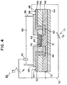
- ISFET 41 is illustrated and comprises substantially planar electrically insulating substrate 44; semiconductor 46 which may be an n-doped or p-doped material, and comprising p-type silicon according to a preferred embodiment deposited atop substrate 44; diffusion regions including source 48 and drain 50 separately formed in semiconductor 46 having a first doping polarity and comprising, for example, n-type silicon according to a preferred embodiment; leads 52 and 54 contacting source 48 and drain 50, respectively, formed from any conductive material such as metal; insulating layer 56 coating semiconductor 46 (and source and drain 48 and 50 formed therein) at all places except where leads 52 and 54 contact source and drain 48 and 50, insulating layer 56 comprising SiO2 according to a preferred embodiment; polymeric material 40 in accordance with the present invention formed atop insulating layer 56 above diffusion region, or channel 51 of semiconductor 46 between source 48 and drain 50, formed in well 57 according to one embodiment; ion selective material 42 formed atop polymeric material 40; and encapsulant
- Region 51 of semiconductor 46 between source 48 and drain 50 has a doping polarity that is either different from that of source 48 and drain 50 or of a different magnitude.
- source 48 and drain 50 may comprise n-type silicon while region 51 may comprise p-type silicon.
- source 48 and drain 50 may be relatively heavily doped to a particular polarity, region 51 being lightly doped to the same polarity.
- Sample 60 which may or may not include an analyte or ion, is provided in contact with material 42, and reference electrode 62 is provided in contact with electrolyte or analyte solution 60. Illustrated in Fig. 3 is a liquid electrolyte 60 contacting material 42 and encapsulant 58 and being contained within boundary 59, such as a beaker or the like.
- Contact 64 contacts lead 52, and contact 68 contacts lead 54, thus the drain circuit of ISFET 41 contains lead 52, contact 64, conductor 70, contact 68, lead 54, drain 50, region 51, source 48 and a potential source 71.
- the drain circuit is in electrical contact with reference electrode 62, thus electrode 62, electrolyte 60, ion selective material 42, polymeric material 40, and potential source 73 complete the gate circuit of ISFET 41.
- Contact 72 in electrical connection with conductor 70, may contact semiconductor 46 to provide a stable reference for the gate and drain circuits of ISFET 41.
- Fig. 4 illustrates a second embodiment of the present invention in which an ISFET incorporates polymeric material 40.
- Components and features common to Figs. 3 and 4 are represented by common numerical designations.
- the metal gate of a field effect transistor is replaced by ion selective material 42, polymeric material 40, electrolyte or analyte solution 60, and reference electrode 62.
- the embodiment illustrated in Fig. 4 additionally comprises ion-barrier layer 74 between polymeric material 40 and insulator 56.
- Layer 74 may comprise a conducting metal such as gold, silver, platinum, copper, brass, zinc, etc., or their oxides or alloys.
- Particularly preferred materials suitable for use as layer 74 are Al2O3, Ta2O5, and Si3N4.
- Exemplary materials suitable for components of ISFET 41 according to the present invention, and exemplary dimensional specifications for the components may be found in U.S. Patent No. 4,502,938, referenced above.
- the "unblocked" junction potential as described above with reference to Fig. 2 is realized according to the embodiment of the present invention defining the transducer of Fig. 3 and Fig. 4.
- ion selective sensor 30 and ISFET 40 are not critical to the present invention. Dimensions typically found in planar electrochemical devices fabricated according to conventional thin-film or thick-film techniques are acceptable. Additionally, although substrate 32 is illustrated in Fig. 2, upon which ion selective sensor 30 is fabricated, sensor 30 may be fabricated without a substrate, in the form of the well-known "dipped" electrode. Such an embodiment will be clearly understood by referring to U.S. Patent No. 3,714,015, and incorporated herein by reference.
- the thick-film technique is exclusively exemplified, it is to be understood that the thin-film technique may be selected; although only a one-electrode device is fabricated, a device including a plurality of electrodes on a single chip could be fabricated, as well as a plurality of transducers on a single chip. Additionally, the specific shape and arrangement of the components of the electrode of the present invention may be significantly altered, such alteration being within the scope of the invention. These and other modifications and their equivalents are understood to be within the scope of the present invention.
- ion selective sensors were fabricated by screen printing a plurality of individual electrodes on a laser scored ceramic wafer, and following the deposition of an ion selective membrane, the wafer was singulated on the laser score lines so as to create a plurality of individual sensor chips.
- procedures will be described as if a single chip were fabricated.
- An ion selective sensor base chip was fabricated on a .457 cm x 1.143 cm electrically insulating composite substrate compromising approximately 96% Al2O3 and approximately 4% binder, available from Coors Ceramic Company, Grand Junction, Colorado.
- the laser score process needed for wafer singulation is available from Lasereliance Technologies, Altamonte Springs, Florida.
- a conductive strip was fabricated by screen printing, using a framed, stainless 325 mesh/.01 mm emulsion-coated screen available from affiliated Manufacturers, Inc., North Branch, New Jersey.
- the silver conductive paste is available as part no. 3571 UF, from Metech Company of Elverson, Pennsylvania.
- the conductive strip was fabricated so as to create an oval electrode with the approximate dimensions of 1.52 mm x .762 mm.
- the paste was fired using a Fast Fire, 7 zone belt furnace with an attached 3 zone dryer available from BTU of Billerica, Massachusetts, in accordance with manufacturer's recommendations.
- a gold conductor and contact pad was screen printed so as to overlap and make contact to the silver conductor.
- the contact pad extends approximately 2.03 mm from the Dielectric coating edge and has a contact area of approximately 1.66 mm.
- the gold paste is available as part no. MTPC10391 from Metech Company, Elverson, Pennsylvania. Firing was carried out according to manufacturer's recommendations.
- a dielectric (glass) passivation was then printed over both conductors with openings so as to define the active electrode area and the contact pads.
- the dielectric paste, part no. 9615, is available from E.I. Dupont, Wilmington, Delaware, and was fired according to manufacturer's recommendations.
- the gold contact pads were masked with .250'' skived TFE film tape with a silicon adhesive available from Green Rubber, Cambridge, Massachusetts.
- the silver electrodes were then galvanostatically plated with silver chloride from 0.1 M KCl for 10 minutes at -2.00 mA.
- the tape was removed and the chip was rinsed in deionized water and air dried.
- a copolymer of MAPTAC and MMA was synthesized according to the following method
- MAPTAC was purchased as a 50 weight percent aqueous solution inhibited with 600 ppm MEHQ from Aldrich of Milwaukee, Wisconsin, and was used as received.
- MMA was purchased from Aldrich of Milwaukee, Wisconsin, and was distilled prior to use.
- Isopropyl alcohol (IPA) was HPLC grade from Fisher of Pittsburgh, Pennsylvania, and was used as received.
- Anhydrous ethanol was from Quantum Chemical of Cincinnati, Ohio, and was used as received.
- Azobisisobutyronitrile (AIBN) was from Kodak Chemical of Rochester, New York, and was recrystallized in acetone prior to use.
- Anhydrous diethyl ether was from Fisher, and was used as received.
- a copolymer having a weight ratio of 25 parts MAPTAC to 75 parts MMA was synthesized as follows. 10 mL of IPA, 5 g of a 50 weight percent aqueous solution of MAPTAC and 7.5 g of MMA were added to a test tube which was then covered with a septum. A needle connected to a nitrogen line was inserted into the septum and the reaction mixture was mixed with nitrogen bubbles for about 5 minutes. 0.11 g of AIBN was next added to the reaction mixture and this was mixed for an additional 20 minutes with nitrogen bubbles. The needle was removed and the test tube was placed in a 70°C water bath for 2.5 hours. The water bath was then removed and the test tube sat capped overnight at room temperature. The polymer was removed from the test tube by breaking the glass. Pieces of polymer were dissolved in a 10% solution of anhydrous ethanol, precipitated into anhydrous diethyl ether, filtered, and then dried 30 minutes with vacuum.
- Silated PVC was synthesized in house, according to EP-A-555952
- a 25/75 weight ratio of MAPTAC/MMA, prepared according to Example 2 was dissolved as a 5% weight solution in ethanol.
- a chip fabricated according to Example 1 was prepared as described in Example 1, and the ethanol solution containing MAPTAC/MMA was drop cast thereover using a Pasteur pipette. The ethanol was driven off by drying at room temperature followed by drying at 80°C for 30 minutes. The resultant MAPTAC/MMA layer had a thickness of about 10 mm.
- the chip was then spun cast with a 1% weight solution of silated PVC in tetrahydrofuran at 4,000 RPM for 30 seconds and cured for 2 hours at 80°C.
- the resultant silated PVC layer had a thickness of about 1 mm.
- a chip including a membrane selective for hydrogen ion was fabricated as follows.
- the pH sensor was prepared by depositing a hydrogen ion selective membrane atop the sensor fabricated in accordance with Example 3 according to the following method.
- Tetrahydrofuran (THF) was purchased from Aldrich, of Milwaukee, Wisconsin.
- Tridodecylamine (TDDA) was purchased from Fluka, of Buchs, Switzerland.
- Potassium tetrakis (p-chlorophenyl) borate (KTpClPB) was purchased from Fluka.
- Dioctylphthalate (DOP) was purchased from Fluka.
- PVC was purchased from Fluka.
- a 10% by weight membrane solution was prepared in THF containing 2 weight percent TDDA, 0.1 weight percent KTpClPB, 65 weight percent DOP, and 33 weight percent PVC.
- a volume of 3.6 ml of membrane solution was solvent cast onto a chip fabricated in accordance with Example 3. The layer was dried at room temperature in a THF environment for about 24 hours. Final membrane thickness was approximately 120 mm.
- a chip including a membrane selective for the potassium ion was fabricated as follows. Valinomycin (VAL) was purchased from Fluka. Diundecylphthalate (DUP) was purchased from Scientific Polymer Products of Ontario, New York. A 10% by weight membrane solution was formulated in THF containing 1 weight percent VAL, 33 weight percent PVC, 66 weight percent DUP, and 0.2 weight percent KTpClPB. A membrane layer was cast atop a chip fabricated in accordance with Example 3 in the manner described in Exhibit 4.
- VAL Valinomycin
- DUP Diundecylphthalate
- a chip including a membrane selective for the sodium ion was fabricated as follows. Methyl monensin ester (MMO) was purchased from Calbiochem of LaJolla, California. o-nitrophenol octyl ether (NPOE) was purchased from Fluka.
- MMO Methyl monensin ester
- NPOE o-nitrophenol octyl ether
- a 10% by weight membrane solution was formulated in THF containing 2 weight percent MMO, 30 weight percent PVC, 67.6 weight percent o-NPOE, and 0.4 weight percent KTpClPB.
- a membrane layer was cast atop a chip fabricated in accordance with Example 3 in the manner described in Example 4.
- a chip including a membrane selective for the calcium ion was fabricated as follows: (R,R)-N,N'-[BIS(11-ethoxycarbonyl)undecyl]-N,N'-4,5-tetramethyl-3,6-doxaoctane diamide (ETH1001) was purchased from Fluka.
- a 10 percent by weight solution in THF was prepared by adding 3.3 weight percent ETH1001, 1.2 weight percent KTpClPB, 30 weight percent PVC, and 6.5.5 weight percent NPOE. The solution was solvent cast onto a chip prepared in accordance with Example 3 in the manner described in Example 4.
- Sample chambers were constructed so as to expose all sample solutions to an area of the ion selective membrane immediately above the reference redox couple.
- a conventional silver/silver chloride reference electrode and the gold contact pad of the pH chip were connected to a high impedance voltmeter, the reference electrode also being exposed to sample solutions.
- the sensors were tested. The sensors were first wetup in pH 7 buffer and initial slopes were determined. The sensors were then soaked for approximately 48 hours in the buffer solution.
- potentiometric selectivity coefficients were determined using the fixed interference method.
- Buffer solutions were: 1) 10 mM NaOH, 130 mM NaCl, 10 mM TRIS, 2) 190 mM KCl, 10 mM KOH, 10 mM TRIS, 3) 60 mM LiOH, 6.6 mM citric acid, 11.4 mM boric acid, 4) 130 mM CaCl2, 20 mM Ca(OH)2, 10 mM TRIS, and 5) 130 mM MgCl2, 20 mM Mg(OH)2, 10 mM TRIS.
- the pH of each solution was adjusted by dropwise addition of 1 N HCl. Slope was determined at the end of the day.
- test sequence was carried out: (A) aqueous test (slope determination and triplicate measurements of a variety of pH standard solutions); (B) the pH of 20 samples of human serum was measured; (C) aqueous test, as in (A); (D) pH measurement of 10 human whole blood samples, followed by a slope determination (WB 1); (E) a repeat of step (D) for a second blood sample (WB 2); (F) a repeat of step (D) for a third blood sample (WB 3); (G) a repeat of the aqueous test of step (A).
- Example 8 The five (5) day whole blood and serum study of Example 8 was carried out using potassium sensors using chips fabricated in accordance with Example 5. Four potassium sensors were fabricated. On day 1, potentiometric selectivity coefficients were determined using the separate solution method. Results were similar to conventional K+ electrodes. On days 2-4, the test sequence described in Example 8 was carried out, with the exception that step A was carried out using 644 Cal and 644 Slope solutions, commercially available from Ciba Corning Diagnostics of Medfield, Massachusetts and potassium was measured rather than pH. The results of this test are given in Tables 2 and 3.
- Example 8 The five day whole blood and serum study described in Example 8 was conducted for sodium sensors using chips fabricated in accordance with Example 6. Sample chambers were constructed as in Example 8. The slope and calibration solutions described in Example 9 were used. The control sensor was a commercially available sodium sensor (Ciba Corning Diagnostics Corp. 200 series glass sodium sensor). Table 4 gives average precision values for 5 sensors fabricated according to this example. The results are very good. Slope, linearity, and selectivity were also good.
- Example 8 The five day whole blood and serum study described in Example 8 was conducted for calcium sensors including chips fabricated in accordance with Example 7. Five sensors were fabricated. Sample chambers were constructed in accordance with Example 8. The slope and calibration solutions were 634 cal and 634 slope solutions, commercially available from Ciba Corning Diagnostics Corp. Table 5 lists average precision values. Precision and accuracy are very good. Linearity, slope and selectivity were also good.
- Transference number determinations in the MAPTAC/MMA membrane material fabricated in accordance with Example 2 were carried out.
- Free-standing MAPTAC/MMA was formed by drop casting from a 5 weight percent solution in ethanol, similar to the drop casting method described in Example 3.
- the membranes were soaked in 160 mM solution of NaCl for about 30 minutes, and swelled to about 2.1 times their dry weight as a result. Circular sections were cut out of the free-standing membranes and mounted in the well-known Phillips bodies.
- the fill solution was the same as the soak solution and a silver/silver chloride internal reference was used.
- EMF measurements were made in beakers with a saturated KCl calomel reference electrode. Transference numbers were determined by the EMF method whereby membrane potentials are measured using electrolyte concentrations C1 and C2 on either side of the membrane. The concentration of NaCl on one side was kept constant at 160 mM and the concentration C2 of NaCl or KNO3 on the other side was varied. Reference to this well-known method may be found in "Transport Phenomena in Membranes", by N. Lakshminarayanaiah, New York, Academic Press, (1969). Results are tabulated in Table 6. Appreciable cationic as well as anionic transport in the films tested was observed. Ionic transport was also observed to be a non-selective phenomenon, as evidenced by the similarity in the results when NaCl is replaced by KNO3.
- a pH sensor was prepared in accordance with Example 4. A 25/75 weight ratio of MAPTAC/MMA in ethanol was spun cast on the chip for 30 seconds at 750 RPM. The chip was air dried. A pH membrane was cast atop the chip in accordance with Example 4. Using 6200C Permanent Mending Tape from 3M Corporation of St. Paul, Minnesota, the tape was pressed atop the chip and slowly removed by pulling upwards at an angle approximately perpendicular to the surface of the chip. Adhesion was observed to be good. Aqueous performance was tested over 40 days and was very good.
Landscapes
- Life Sciences & Earth Sciences (AREA)
- Chemical & Material Sciences (AREA)
- Health & Medical Sciences (AREA)
- General Physics & Mathematics (AREA)
- Pathology (AREA)
- Molecular Biology (AREA)
- Chemical Kinetics & Catalysis (AREA)
- Electrochemistry (AREA)
- Physics & Mathematics (AREA)
- Analytical Chemistry (AREA)
- Biochemistry (AREA)
- General Health & Medical Sciences (AREA)
- Immunology (AREA)
- Engineering & Computer Science (AREA)
- Microelectronics & Electronic Packaging (AREA)
- Investigating Or Analyzing Materials By The Use Of Electric Means (AREA)
- Battery Electrode And Active Subsutance (AREA)
- Secondary Cells (AREA)
- Investigating Or Analyzing Materials By The Use Of Fluid Adsorption Or Reactions (AREA)
- Semiconductor Memories (AREA)
- Measurement Of The Respiration, Hearing Ability, Form, And Blood Characteristics Of Living Organisms (AREA)
- Compositions Of Macromolecular Compounds (AREA)
- Addition Polymer Or Copolymer, Post-Treatments, Or Chemical Modifications (AREA)
- Contacts (AREA)
- Coupling Device And Connection With Printed Circuit (AREA)
Applications Claiming Priority (2)
| Application Number | Priority Date | Filing Date | Title |
|---|---|---|---|
| US08/121,822 US5804049A (en) | 1993-09-15 | 1993-09-15 | Material for establishing solid state contact for ion selective electrodes |
| US121822 | 1993-09-15 |
Publications (2)
| Publication Number | Publication Date |
|---|---|
| EP0643299A1 true EP0643299A1 (fr) | 1995-03-15 |
| EP0643299B1 EP0643299B1 (fr) | 2002-12-18 |
Family
ID=22399026
Family Applications (1)
| Application Number | Title | Priority Date | Filing Date |
|---|---|---|---|
| EP94306703A Expired - Lifetime EP0643299B1 (fr) | 1993-09-15 | 1994-09-13 | Electrodes sélectives aux ions |
Country Status (10)
| Country | Link |
|---|---|
| US (3) | US5804049A (fr) |
| EP (1) | EP0643299B1 (fr) |
| JP (1) | JP3588146B2 (fr) |
| KR (1) | KR950009250A (fr) |
| AT (1) | ATE230110T1 (fr) |
| AU (1) | AU673045B2 (fr) |
| CA (1) | CA2131936A1 (fr) |
| DE (1) | DE69431900T2 (fr) |
| DK (1) | DK0643299T3 (fr) |
| ES (1) | ES2184753T3 (fr) |
Cited By (3)
| Publication number | Priority date | Publication date | Assignee | Title |
|---|---|---|---|---|
| US5637642A (en) * | 1992-01-07 | 1997-06-10 | Chiron Diagnostics Corporation | PVC adhesives for electrodes and other applications |
| WO2000054039A1 (fr) * | 1999-03-10 | 2000-09-14 | Elizabeth Anne Howlett Hall | Matiere polymere selective |
| EP3012623A1 (fr) * | 2014-10-22 | 2016-04-27 | ARKRAY, Inc. | Capteur électrochimique et procédé de fabrication associé |
Families Citing this family (29)
| Publication number | Priority date | Publication date | Assignee | Title |
|---|---|---|---|---|
| US5804049A (en) * | 1993-09-15 | 1998-09-08 | Chiron Diagnostics Corporation | Material for establishing solid state contact for ion selective electrodes |
| US5958214A (en) * | 1994-09-12 | 1999-09-28 | Mst Micro-Sensor-Technologie Gmbh | Electrochemical sensor with a solid electrolyte for measuring the gas concentration |
| KR100446164B1 (ko) * | 1997-07-31 | 2004-10-28 | 주식회사 휴비스 | 폴리에스테르 섬유의 연속 사 염색방법 |
| US6338790B1 (en) | 1998-10-08 | 2002-01-15 | Therasense, Inc. | Small volume in vitro analyte sensor with diffusible or non-leachable redox mediator |
| CA2391423A1 (fr) | 1999-11-15 | 2001-05-25 | Therasense, Inc. | Complexes polymeres de metaux de transition et leurs utilisations |
| US8268143B2 (en) * | 1999-11-15 | 2012-09-18 | Abbott Diabetes Care Inc. | Oxygen-effect free analyte sensor |
| US8444834B2 (en) | 1999-11-15 | 2013-05-21 | Abbott Diabetes Care Inc. | Redox polymers for use in analyte monitoring |
| US6793789B2 (en) * | 2000-09-30 | 2004-09-21 | Geun Sig Cha | Reference electrode with a polymeric reference electrode membrane |
| US8070934B2 (en) | 2001-05-11 | 2011-12-06 | Abbott Diabetes Care Inc. | Transition metal complexes with (pyridyl)imidazole ligands |
| US8226814B2 (en) * | 2001-05-11 | 2012-07-24 | Abbott Diabetes Care Inc. | Transition metal complexes with pyridyl-imidazole ligands |
| US6676816B2 (en) | 2001-05-11 | 2004-01-13 | Therasense, Inc. | Transition metal complexes with (pyridyl)imidazole ligands and sensors using said complexes |
| US7101472B2 (en) * | 2002-03-13 | 2006-09-05 | The Charles Stark Draper Laboratory, Inc. | Microfluidic ion-selective electrode sensor system |
| US7407570B2 (en) * | 2002-03-13 | 2008-08-05 | The Charles Stark Draper Laboratory, Inc. | Disposable, self-administered electrolyte test |
| AT413766B8 (de) * | 2003-05-15 | 2006-06-15 | Hoffmann La Roche | Potentiometrische, ionenselektive elektrode |
| TWI223707B (en) * | 2003-12-30 | 2004-11-11 | Univ Nat Yunlin Sci & Tech | Drug sensor for the alkaloid measurement, the preparation thereof, and measuring systems comprising the same |
| EP1706734A1 (fr) * | 2004-01-21 | 2006-10-04 | Rosemount Analytical Inc. | Capteur transistor a effet de champ sensible aux ions (isfet) a configuration de grille amelioree |
| US7737433B2 (en) * | 2004-03-08 | 2010-06-15 | The Ohio State University Research Foundation | Electronic junction devices featuring redox electrodes |
| TWI283512B (en) * | 2004-07-08 | 2007-07-01 | Via Tech Inc | Transconductance filtering circuit |
| TWI234284B (en) * | 2004-08-30 | 2005-06-11 | Univ Nat Yunlin Sci & Tech | Manufacturing method of tin-oxide extending-type gate ion sensitive transistor, and the related detection circuit and read circuit |
| ES2377571T3 (es) * | 2005-10-24 | 2012-03-29 | The Procter & Gamble Company | Composiciones y sistemas para el cuidado de tejidos que comprenden microemulsiones de organosilicona y métodos que emplean los mismos |
| US7678752B2 (en) * | 2005-10-24 | 2010-03-16 | The Procter & Gamble Company | Fabric care composition comprising organosilicone microemulsion and anionic/nitrogen-containing surfactant system |
| TWI302197B (en) * | 2006-01-04 | 2008-10-21 | Univ Nat Yunlin Sci & Tech | Reference ph sensor, the preparation and application thereof |
| US7790112B2 (en) * | 2006-03-30 | 2010-09-07 | Council of Scientific & Industual Research | Biosensor to determine potassium concentration in human blood serum |
| KR101195612B1 (ko) * | 2006-04-10 | 2012-10-29 | 삼성전자주식회사 | 금층을 포함하는 전계 효과 트랜지스터, 상기 전계 효과 트랜지스터를 포함하는 미세유동장치, 및 상기 전계 효과 트랜지스터 및 미세유동장치를 이용하여 티올기를 포함하는 분석물을 검출하는 방법 |
| US20110284394A1 (en) * | 2007-02-14 | 2011-11-24 | The Board of Trustees of the University Illinois Office Technology | Portable Electrochemical Multiphase Microreactor for Sensing Trace Chemical Vapors |
| MY179070A (en) * | 2007-12-06 | 2020-10-27 | Mimos Berhad | Method and system for applying ion-selective membrane on isfet surface |
| US9970914B1 (en) | 2014-04-04 | 2018-05-15 | The United States Of America As Represented By The Administrator Of National Aeronautics And Space Administration | Gas sensors with contact pads |
| DE102019216327A1 (de) * | 2019-10-23 | 2021-04-29 | Fraunhofer-Gesellschaft zur Förderung der angewandten Forschung e.V. | Sensor mit einer festkörper-schichtstruktur und verfahren zur herstellung eines sensors |
| KR102297769B1 (ko) * | 2020-04-28 | 2021-09-06 | 주식회사 피앤씨랩스 | 셀룰로오스 부직포 머서화 장치 및 이를 이용한 머서화 방법 |
Citations (5)
| Publication number | Priority date | Publication date | Assignee | Title |
|---|---|---|---|---|
| US4214968A (en) * | 1978-04-05 | 1980-07-29 | Eastman Kodak Company | Ion-selective electrode |
| EP0063455A1 (fr) * | 1981-04-09 | 1982-10-27 | Ciba Corning Diagnostics Corp. | Procédé de fabrication de dispositifs de groupes microélectroniques scellés, chimiquement sensibles |
| DE3222464A1 (de) * | 1981-06-15 | 1982-12-30 | Fuji Photo Film Co., Ltd., Minami-Ashigara, Kanagawa | Elektrode fuer die bestimmung der halogenionen-konzentration und durchlaessige kunststoffe fuer deren herstellung |
| US4434249A (en) * | 1982-06-28 | 1984-02-28 | Electrochemical Technology Corp. | Method of preparing acrylic ion-transfer membranes |
| EP0325562A2 (fr) * | 1988-01-21 | 1989-07-26 | Electro-Nucleonics, Inc. | Electrodes séches sélectives d'ions pour la détermination des espèces ioniques dans des milieux aqueux |
Family Cites Families (13)
| Publication number | Priority date | Publication date | Assignee | Title |
|---|---|---|---|---|
| US3714015A (en) * | 1970-09-04 | 1973-01-30 | Gen Electric | Sensor with ion exchange resin electrolyte |
| US4020830A (en) | 1975-03-12 | 1977-05-03 | The University Of Utah | Selective chemical sensitive FET transducers |
| US4571292A (en) * | 1982-08-12 | 1986-02-18 | Case Western Reserve University | Apparatus for electrochemical measurements |
| US4739380A (en) * | 1984-01-19 | 1988-04-19 | Integrated Ionics, Inc. | Integrated ambient sensing devices and methods of manufacture |
| US4734184A (en) | 1985-08-29 | 1988-03-29 | Diamond Sensor Systems, Inc. | Self-activating hydratable solid-state electrode apparatus |
| CA1285614C (fr) * | 1986-11-13 | 1991-07-02 | John E. Heider | Electrode semiconductrice de reference |
| CA1315927C (fr) | 1986-12-10 | 1993-04-13 | Terumo Kabushiki Kaisha | Membrane ionique et chambre d'ionisation comportant cette membrane |
| US4816130A (en) * | 1987-07-02 | 1989-03-28 | Becton, Dickinson And Company | Blood electrolyte sensors including crosslinked polyetherurethane membranes |
| US5183549A (en) * | 1990-01-26 | 1993-02-02 | Commtech International Management Corporation | Multi-analyte sensing electrolytic cell |
| CA2047991A1 (fr) * | 1991-02-04 | 1992-08-05 | John Musacchio | Systeme a contact solide pour capteurs a potentiometre |
| US5120422A (en) | 1991-03-01 | 1992-06-09 | Ceramatec, Inc. | Sodium ion sensor |
| US5804049A (en) * | 1993-09-15 | 1998-09-08 | Chiron Diagnostics Corporation | Material for establishing solid state contact for ion selective electrodes |
| US5738774A (en) | 1995-07-28 | 1998-04-14 | The Governors Of The University Of Alberta | Eva containing ion selective membranes and methods of making same |
-
1993
- 1993-09-15 US US08/121,822 patent/US5804049A/en not_active Expired - Lifetime
-
1994
- 1994-03-23 AU AU57998/94A patent/AU673045B2/en not_active Ceased
- 1994-09-13 ES ES94306703T patent/ES2184753T3/es not_active Expired - Lifetime
- 1994-09-13 DE DE69431900T patent/DE69431900T2/de not_active Expired - Lifetime
- 1994-09-13 CA CA002131936A patent/CA2131936A1/fr not_active Abandoned
- 1994-09-13 AT AT94306703T patent/ATE230110T1/de not_active IP Right Cessation
- 1994-09-13 KR KR1019940023102A patent/KR950009250A/ko not_active Ceased
- 1994-09-13 EP EP94306703A patent/EP0643299B1/fr not_active Expired - Lifetime
- 1994-09-13 DK DK94306703T patent/DK0643299T3/da active
- 1994-09-16 JP JP22143694A patent/JP3588146B2/ja not_active Expired - Lifetime
-
1998
- 1998-02-26 US US09/031,491 patent/US6251246B1/en not_active Expired - Lifetime
-
2001
- 2001-04-12 US US09/834,000 patent/US6416646B2/en not_active Expired - Lifetime
Patent Citations (5)
| Publication number | Priority date | Publication date | Assignee | Title |
|---|---|---|---|---|
| US4214968A (en) * | 1978-04-05 | 1980-07-29 | Eastman Kodak Company | Ion-selective electrode |
| EP0063455A1 (fr) * | 1981-04-09 | 1982-10-27 | Ciba Corning Diagnostics Corp. | Procédé de fabrication de dispositifs de groupes microélectroniques scellés, chimiquement sensibles |
| DE3222464A1 (de) * | 1981-06-15 | 1982-12-30 | Fuji Photo Film Co., Ltd., Minami-Ashigara, Kanagawa | Elektrode fuer die bestimmung der halogenionen-konzentration und durchlaessige kunststoffe fuer deren herstellung |
| US4434249A (en) * | 1982-06-28 | 1984-02-28 | Electrochemical Technology Corp. | Method of preparing acrylic ion-transfer membranes |
| EP0325562A2 (fr) * | 1988-01-21 | 1989-07-26 | Electro-Nucleonics, Inc. | Electrodes séches sélectives d'ions pour la détermination des espèces ioniques dans des milieux aqueux |
Non-Patent Citations (4)
| Title |
|---|
| ANNAKA M ET AL: "Multiple phases of polymer gels", NATURE, 30 JAN. 1992, UK, VOL. 355, NR. 6359, PAGE(S) 430 - 432, ISSN 0028-0836 * |
| C.L.BALLESTRASSE ; T.R.BECK: "ACRYLIC ION-TRANSFER POLYMERS", JOURNAL OF THE ELECTROCHEMICAL SOCIETY, vol. 134, no. 11, November 1987 (1987-11-01), MANCHESTER, NEW HAMPSHIRE US, pages 2745 - 2749 * |
| J.R.SANDIFER: "theory of interfacial potential differences : Effects of Adsorption onto Hydrated (Gel) and Nonhydrated Surfaces.", ANALYTICAL CHEMISTRY, vol. 60, no. 15, August 1988 (1988-08-01), COLUMBUS US, pages 1553 - 1562 * |
| W.E.MORF ; W.SIMON: "Influence of anionic sites in solvent polymeric membranes on potential response and ion-selectivity behaviour.", ANALYTICAL LETTERS, vol. 22, no. 5, 1989, ZURICH, pages 1171 - 1184, XP001347541 * |
Cited By (4)
| Publication number | Priority date | Publication date | Assignee | Title |
|---|---|---|---|---|
| US5637642A (en) * | 1992-01-07 | 1997-06-10 | Chiron Diagnostics Corporation | PVC adhesives for electrodes and other applications |
| WO2000054039A1 (fr) * | 1999-03-10 | 2000-09-14 | Elizabeth Anne Howlett Hall | Matiere polymere selective |
| EP3012623A1 (fr) * | 2014-10-22 | 2016-04-27 | ARKRAY, Inc. | Capteur électrochimique et procédé de fabrication associé |
| US10473611B2 (en) | 2014-10-22 | 2019-11-12 | Arkray, Inc. | Electrochemical sensor and method for producing electrochemical sensor |
Also Published As
| Publication number | Publication date |
|---|---|
| US20010032784A1 (en) | 2001-10-25 |
| ATE230110T1 (de) | 2003-01-15 |
| JP3588146B2 (ja) | 2004-11-10 |
| EP0643299B1 (fr) | 2002-12-18 |
| DK0643299T3 (da) | 2003-03-24 |
| AU673045B2 (en) | 1996-10-24 |
| DE69431900T2 (de) | 2003-09-18 |
| JPH07167827A (ja) | 1995-07-04 |
| DE69431900D1 (de) | 2003-01-30 |
| US5804049A (en) | 1998-09-08 |
| AU5799894A (en) | 1995-04-13 |
| ES2184753T3 (es) | 2003-04-16 |
| KR950009250A (ko) | 1995-04-21 |
| CA2131936A1 (fr) | 1995-03-16 |
| US6251246B1 (en) | 2001-06-26 |
| US6416646B2 (en) | 2002-07-09 |
Similar Documents
| Publication | Publication Date | Title |
|---|---|---|
| US6251246B1 (en) | Material for establishing solid state contact for ion selective electrodes | |
| US5911862A (en) | Material for establishing solid state contact for ion selective electrodes | |
| EP0235470B1 (fr) | Transistor à effet de champ sensible aux ions | |
| US20020029979A1 (en) | Sensors and sensing methods for detecting analytes based on changes in pKa of a sensing polymer | |
| WO1986001894A1 (fr) | Electrodes a selectivite ionique | |
| US4981570A (en) | Ion carrier membrane, and ion sensor having same | |
| EP0236440B1 (fr) | Capteur electrochimique sensible aux ions et procede de determination de concentrations ioniques | |
| JP3135956B2 (ja) | ソリッドコンタクトとこれを用いた電位差センサ装置およびセンサ装置による方法 | |
| US8394247B2 (en) | Anion concentration measuring device and anion concentration measuring element | |
| Skowronska-Ptasinska et al. | Reference field effect transistors based on chemically modified ISFETs | |
| US4921591A (en) | Ion sensors and their divided parts | |
| Wróblewski et al. | Towards advanced chemical microsensors—an overview | |
| Choi et al. | Covalently attached ionophores extend the working range of potentiometric pH sensors with poly (decyl methacrylate) sensing membranes | |
| US20050263410A1 (en) | Ion-selective electrodes and method of fabricating sensing units thereof | |
| EP0138150A2 (fr) | Membranes pour électrodes de diagnostic à paires spécifiques d'enzyme/ionophore | |
| CN114019005B (zh) | 一种基于离子迁移放大效应的聚合物敏感膜的高精度电化学检测方法 | |
| WO1997005478A1 (fr) | Membranes selectives d'ions contenant de l'eva et leurs procedes de production | |
| Sun et al. | Internal solid contact electrode for the determination of salbutamol sulfate in pharmaceutical formulation | |
| Ramanaviciene et al. | Molecularly imprinted polypyrrole for sensor design | |
| Cheng et al. | Study on all-solid-state chloride sensor based on tin oxide/indium tin oxide glass | |
| TWI485400B (zh) | 氯離子感測系統 | |
| CN114166904B (zh) | 一种检测硝酸根离子的方法 | |
| Merzouk et al. | Development of Li+ Selective Microelectrode Using PPy [3, 3'-Co (1, 2-C^ sub 2^ B^ sub 9^ H^ sub 11^)^ sub 2^] as a Solid Contact | |
| JPH02266256A (ja) | 液膜型塩素イオン選択性電極 | |
| JPS61270653A (ja) | イオン選択性電界効果トランジスタ−電極 |
Legal Events
| Date | Code | Title | Description |
|---|---|---|---|
| PUAI | Public reference made under article 153(3) epc to a published international application that has entered the european phase |
Free format text: ORIGINAL CODE: 0009012 |
|
| AK | Designated contracting states |
Kind code of ref document: A1 Designated state(s): AT BE CH DE DK ES FR GB IT LI NL |
|
| 17P | Request for examination filed |
Effective date: 19950413 |
|
| 17Q | First examination report despatched |
Effective date: 19970716 |
|
| RAP1 | Party data changed (applicant data changed or rights of an application transferred) |
Owner name: BAYER CORPORATION |
|
| RTI1 | Title (correction) |
Free format text: ION SELECTIVE ELECTRODES |
|
| GRAG | Despatch of communication of intention to grant |
Free format text: ORIGINAL CODE: EPIDOS AGRA |
|
| RTI1 | Title (correction) |
Free format text: ION SELECTIVE ELECTRODES |
|
| GRAG | Despatch of communication of intention to grant |
Free format text: ORIGINAL CODE: EPIDOS AGRA |
|
| GRAG | Despatch of communication of intention to grant |
Free format text: ORIGINAL CODE: EPIDOS AGRA |
|
| GRAH | Despatch of communication of intention to grant a patent |
Free format text: ORIGINAL CODE: EPIDOS IGRA |
|
| GRAH | Despatch of communication of intention to grant a patent |
Free format text: ORIGINAL CODE: EPIDOS IGRA |
|
| GRAA | (expected) grant |
Free format text: ORIGINAL CODE: 0009210 |
|
| AK | Designated contracting states |
Kind code of ref document: B1 Designated state(s): AT BE CH DE DK ES FR GB IT LI NL |
|
| PG25 | Lapsed in a contracting state [announced via postgrant information from national office to epo] |
Ref country code: LI Free format text: LAPSE BECAUSE OF FAILURE TO SUBMIT A TRANSLATION OF THE DESCRIPTION OR TO PAY THE FEE WITHIN THE PRESCRIBED TIME-LIMIT Effective date: 20021218 Ref country code: CH Free format text: LAPSE BECAUSE OF FAILURE TO SUBMIT A TRANSLATION OF THE DESCRIPTION OR TO PAY THE FEE WITHIN THE PRESCRIBED TIME-LIMIT Effective date: 20021218 Ref country code: BE Free format text: LAPSE BECAUSE OF FAILURE TO SUBMIT A TRANSLATION OF THE DESCRIPTION OR TO PAY THE FEE WITHIN THE PRESCRIBED TIME-LIMIT Effective date: 20021218 Ref country code: AT Free format text: LAPSE BECAUSE OF FAILURE TO SUBMIT A TRANSLATION OF THE DESCRIPTION OR TO PAY THE FEE WITHIN THE PRESCRIBED TIME-LIMIT Effective date: 20021218 |
|
| REF | Corresponds to: |
Ref document number: 230110 Country of ref document: AT Date of ref document: 20030115 Kind code of ref document: T |
|
| REG | Reference to a national code |
Ref country code: GB Ref legal event code: FG4D |
|
| REG | Reference to a national code |
Ref country code: CH Ref legal event code: EP |
|
| REF | Corresponds to: |
Ref document number: 69431900 Country of ref document: DE Date of ref document: 20030130 Kind code of ref document: P Ref document number: 69431900 Country of ref document: DE Date of ref document: 20030130 |
|
| REG | Reference to a national code |
Ref country code: DK Ref legal event code: T3 |
|
| REG | Reference to a national code |
Ref country code: ES Ref legal event code: FG2A Ref document number: 2184753 Country of ref document: ES Kind code of ref document: T3 |
|
| REG | Reference to a national code |
Ref country code: CH Ref legal event code: PL |
|
| ET | Fr: translation filed | ||
| PLBE | No opposition filed within time limit |
Free format text: ORIGINAL CODE: 0009261 |
|
| STAA | Information on the status of an ep patent application or granted ep patent |
Free format text: STATUS: NO OPPOSITION FILED WITHIN TIME LIMIT |
|
| 26N | No opposition filed |
Effective date: 20030919 |
|
| PGFP | Annual fee paid to national office [announced via postgrant information from national office to epo] |
Ref country code: NL Payment date: 20040816 Year of fee payment: 11 |
|
| PGFP | Annual fee paid to national office [announced via postgrant information from national office to epo] |
Ref country code: ES Payment date: 20041008 Year of fee payment: 11 |
|
| PG25 | Lapsed in a contracting state [announced via postgrant information from national office to epo] |
Ref country code: IT Free format text: LAPSE BECAUSE OF NON-PAYMENT OF DUE FEES;WARNING: LAPSES OF ITALIAN PATENTS WITH EFFECTIVE DATE BEFORE 2007 MAY HAVE OCCURRED AT ANY TIME BEFORE 2007. THE CORRECT EFFECTIVE DATE MAY BE DIFFERENT FROM THE ONE RECORDED. Effective date: 20050913 |
|
| PG25 | Lapsed in a contracting state [announced via postgrant information from national office to epo] |
Ref country code: ES Free format text: LAPSE BECAUSE OF NON-PAYMENT OF DUE FEES Effective date: 20050914 |
|
| PG25 | Lapsed in a contracting state [announced via postgrant information from national office to epo] |
Ref country code: NL Free format text: LAPSE BECAUSE OF NON-PAYMENT OF DUE FEES Effective date: 20060401 |
|
| NLV4 | Nl: lapsed or anulled due to non-payment of the annual fee |
Effective date: 20060401 |
|
| REG | Reference to a national code |
Ref country code: ES Ref legal event code: FD2A Effective date: 20050914 |
|
| REG | Reference to a national code |
Ref country code: GB Ref legal event code: 732E Free format text: REGISTERED BETWEEN 20101104 AND 20101110 |
|
| REG | Reference to a national code |
Ref country code: FR Ref legal event code: TP |
|
| PGFP | Annual fee paid to national office [announced via postgrant information from national office to epo] |
Ref country code: DK Payment date: 20130918 Year of fee payment: 20 |
|
| PGFP | Annual fee paid to national office [announced via postgrant information from national office to epo] |
Ref country code: GB Payment date: 20130911 Year of fee payment: 20 Ref country code: FR Payment date: 20130924 Year of fee payment: 20 |
|
| PGFP | Annual fee paid to national office [announced via postgrant information from national office to epo] |
Ref country code: DE Payment date: 20131120 Year of fee payment: 20 |
|
| REG | Reference to a national code |
Ref country code: DK Ref legal event code: EUP Effective date: 20140913 |
|
| REG | Reference to a national code |
Ref country code: DE Ref legal event code: R071 Ref document number: 69431900 Country of ref document: DE |
|
| REG | Reference to a national code |
Ref country code: GB Ref legal event code: PE20 Expiry date: 20140912 |
|
| PG25 | Lapsed in a contracting state [announced via postgrant information from national office to epo] |
Ref country code: DE Free format text: LAPSE BECAUSE OF EXPIRATION OF PROTECTION Effective date: 20140916 |
|
| PG25 | Lapsed in a contracting state [announced via postgrant information from national office to epo] |
Ref country code: GB Free format text: LAPSE BECAUSE OF EXPIRATION OF PROTECTION Effective date: 20140912 |