EP0649030A1 - Méthode d'inspection d'éléments de connection et dispositif d'inspection d'éléments de connection - Google Patents
Méthode d'inspection d'éléments de connection et dispositif d'inspection d'éléments de connection Download PDFInfo
- Publication number
- EP0649030A1 EP0649030A1 EP94307635A EP94307635A EP0649030A1 EP 0649030 A1 EP0649030 A1 EP 0649030A1 EP 94307635 A EP94307635 A EP 94307635A EP 94307635 A EP94307635 A EP 94307635A EP 0649030 A1 EP0649030 A1 EP 0649030A1
- Authority
- EP
- European Patent Office
- Prior art keywords
- terminal
- connecting element
- inspected
- image
- predetermined
- Prior art date
- Legal status (The legal status is an assumption and is not a legal conclusion. Google has not performed a legal analysis and makes no representation as to the accuracy of the status listed.)
- Granted
Links
- 238000000034 method Methods 0.000 title claims abstract description 21
- 238000007689 inspection Methods 0.000 claims description 37
- 230000001678 irradiating effect Effects 0.000 claims description 26
- 238000012545 processing Methods 0.000 claims description 21
- 238000003384 imaging method Methods 0.000 claims description 19
- 238000003780 insertion Methods 0.000 claims description 14
- 230000037431 insertion Effects 0.000 claims description 14
- 238000001514 detection method Methods 0.000 description 4
- 238000010276 construction Methods 0.000 description 3
- 239000000463 material Substances 0.000 description 3
- 239000004020 conductor Substances 0.000 description 2
- 238000007796 conventional method Methods 0.000 description 2
- 239000011521 glass Substances 0.000 description 2
- 239000013307 optical fiber Substances 0.000 description 2
- 230000004044 response Effects 0.000 description 2
- 241000282414 Homo sapiens Species 0.000 description 1
- 229910052782 aluminium Inorganic materials 0.000 description 1
- XAGFODPZIPBFFR-UHFFFAOYSA-N aluminium Chemical compound [Al] XAGFODPZIPBFFR-UHFFFAOYSA-N 0.000 description 1
- 238000012790 confirmation Methods 0.000 description 1
- 238000010586 diagram Methods 0.000 description 1
- 229910052736 halogen Inorganic materials 0.000 description 1
- 150000002367 halogens Chemical class 0.000 description 1
- 229910052751 metal Inorganic materials 0.000 description 1
- 239000002184 metal Substances 0.000 description 1
- 230000003287 optical effect Effects 0.000 description 1
- 238000007747 plating Methods 0.000 description 1
- 238000002360 preparation method Methods 0.000 description 1
- 238000003825 pressing Methods 0.000 description 1
- 238000012795 verification Methods 0.000 description 1
- 230000000007 visual effect Effects 0.000 description 1
- 238000004804 winding Methods 0.000 description 1
Images





Classifications
-
- G—PHYSICS
- G01—MEASURING; TESTING
- G01R—MEASURING ELECTRIC VARIABLES; MEASURING MAGNETIC VARIABLES
- G01R31/00—Arrangements for testing electric properties; Arrangements for locating electric faults; Arrangements for electrical testing characterised by what is being tested not provided for elsewhere
- G01R31/28—Testing of electronic circuits, e.g. by signal tracer
- G01R31/302—Contactless testing
- G01R31/308—Contactless testing using non-ionising electromagnetic radiation, e.g. optical radiation
-
- G—PHYSICS
- G01—MEASURING; TESTING
- G01R—MEASURING ELECTRIC VARIABLES; MEASURING MAGNETIC VARIABLES
- G01R31/00—Arrangements for testing electric properties; Arrangements for locating electric faults; Arrangements for electrical testing characterised by what is being tested not provided for elsewhere
- G01R31/50—Testing of electric apparatus, lines, cables or components for short-circuits, continuity, leakage current or incorrect line connections
- G01R31/66—Testing of connections, e.g. of plugs or non-disconnectable joints
-
- G—PHYSICS
- G01—MEASURING; TESTING
- G01R—MEASURING ELECTRIC VARIABLES; MEASURING MAGNETIC VARIABLES
- G01R31/00—Arrangements for testing electric properties; Arrangements for locating electric faults; Arrangements for electrical testing characterised by what is being tested not provided for elsewhere
- G01R31/50—Testing of electric apparatus, lines, cables or components for short-circuits, continuity, leakage current or incorrect line connections
- G01R31/66—Testing of connections, e.g. of plugs or non-disconnectable joints
- G01R31/68—Testing of releasable connections, e.g. of terminals mounted on a printed circuit board
- G01R31/69—Testing of releasable connections, e.g. of terminals mounted on a printed circuit board of terminals at the end of a cable or a wire harness; of plugs; of sockets, e.g. wall sockets or power sockets in appliances
Definitions
- the present invention relates to a connecting element inspecting method and a connecting element inspecting device for detecting a state where terminals are mounted in terminal containing holes, inclusion of foreign materials into the terminal containing holes, and the like in a connecting element such as a connector or a socket and judging whether the connecting element is accepted or rejected.
- a terminal In a connecting element, for example, a connector, a terminal has been conventionally inserted into a terminal containing hole opening to a connecting surface to another connector to a predetermined position from the rear thereof.
- the terminal In the connector, the terminal is generally held in the predetermined position by a lance provided on the side of a connector housing or on the side of the terminal.
- a lot of connectors fabricated include one in which a terminal is not inserted to the above described predetermined position. Such a connector must be eliminated by inspection.
- examples of a conventionally known inspecting device for inspecting a connector include one so adapted as to elastically push a front end of a terminal by a pin elastically urged by a spring and mechanically push out the terminal incompletely inserted and then, check the conduction of the terminal (see Japanese Utility type Laid-Open Gazette No. 47093/1987).
- a connector in a so-called half-inserted state in which a terminal is not completely inserted to a predetermined position, although it is engaged with a connector housing to such a extent that it receives an engaging force at a certain level by a lance.
- the terminal can be generally pushed out by an urging force produced by a pin. If each electric wire is bound by tape winding or the like, however, the terminal cannot be pushed out by the urging force produced by the pin, so that the connector passes the check of the conduction.
- this connector is actually connected to another connector, the terminal is pushed out by a corresponding terminal in the other connector or the terminal is moved by causes such as vibration during its use, so that the connector is incompletely connected.
- the present invention has been made in view of the foregoing problems and has for an object to provide a connecting element inspecting method and a connecting element inspecting device which can inspect a connecting element efficiently and with high precision without damaging a terminal or the like and is also applicable to a small-sized and multipolar connecting element.
- a connecting element inspecting method for inspecting a connecting element having i) a connecting surface to another connecting element paired with the connecting element, ii) a plurality of terminal containing holes opening to the connecting surface, and iii) terminals respectively inserted into the predetermined terminal containing holes in a predetermined direction of insertion and contained therein, comprising the steps of inputting image data of the connecting surface obtained using light reflected in a direction intersecting the predetermined direction of insertion from the connecting surface, setting an image region to be inspected in relation to the predetermined terminal containing hole to be inspected on the basis of the image data, calculating the percentage of the area of a portion occupied by the terminal in the image region to be inspected, and judging whether the connecting element is accepted or rejected in relation to the predetermined terminal containing hole to be inspected depending on whether or not the percentage satisfies predetermined judgment conditions.
- the image region to be inspected in relation to the terminal containing hole to be inspected is set, and the percentage of the area of the portion occupied by the terminal in the image region to be inspected is found. It is judged that the connecting element to be inspected is rejected on the basis of the found percentage of the area.
- the above described rejection is caused by the reasons such as the reason that the terminal is not properly mounted, for example, the terminal slips off and the terminal is half-inserted and the reason that foreign materials enter the terminal containing hole.
- the half-inserted state of the terminal cannot be detected.
- the half-inserted state of the terminal can be also detected, so that the detection precision is high.
- the present invention is also applicable to a small-sized and multipolar connecting element. Particularly, the light reflected in the direction intersecting the direction of insertion of the terminal from the connecting surface is used, thereby to make it possible to reliably detect the shift in the position of the terminal in the direction of insertion or the direction opposite to the direction of insertion.
- a connecting element inspecting device for inspecting a connecting element having i) a connecting surface to another connecting element paired with the connecting element, ii) terminal containing holes opening to the connecting surface, and iii) terminals respectively inserted into the predetermined terminal containing hole in a predetermined direction of insertion and contained therein, comprises light irradiating means for irradiating the connecting surface to the connecting element by parallel light entering the terminal containing holes, imaging means so disposed that light reflected in a direction intersecting the predetermined direction of insertion from the connecting surface can be received for imaging the connecting surface using the reflected light, image region setting means for setting an image region to be inspected in relation to the predetermined terminal containing hole to be inspected on the basis of image data from the imaging means, percentage calculating means for calculating the percentage of the area of a portion occupied by the terminal in the image region to be inspected, and judging means for judging whether the connecting element is accepted or rejected in relation to the predetermined terminal
- the connecting surface is imaged using the parallel light by the light irradiating means, thereby to make it possible to obtain an image high in position precision, so that the inspection precision is high.
- the connecting surface is imaged from the direction intersecting the direction of insertion of the terminal, thereby to make it possible to reliably detect the shift in the position of the terminal in the direction of insertion or the direction opposite to the direction of insertion, so that the inspection precision can be further improved. Consequently, it is possible to also detect the half-inserted state of the terminal. Further, it is possible to inspect the connecting element very efficiently without damaging the terminal. Further, the present invention is also applicable to a small-sized and multipolar connecting element.
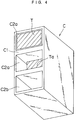
- an end surface of a housing CH of a connector C is constructed as a connecting surface C1 to a corresponding connector (not shown), and a plurality of terminal containing holes C2 disposed crosswise open to the connecting surface C1.
- a plurality of types of specifications which are judged depending on the type and the number of poles are set in the connector C.
- the plurality of terminal containing holes C2 are divided into terminal containing holes C2a each set so as to contain a terminal T by inserting the terminal T from the rear of the housing CH (terminal containing holes in the upper stage in Fig. 3) and terminal containing holes C2b each set so as to avoid containing a terminal T (terminal containing holes in the lower stage in Fig. 3) depending on the respective specifications.
- a state where a front end of the terminal T retreats from the connecting surface C1 by a distance d1 is a state where the terminal is properly mounted.
- a lance L is engaged with an engaging projection Z of the housing CH. If the lance L is not engaged or incompletely engaged, the terminal T is not properly mounted.
- the terminal T in the upper stage is properly mounted, and a terminal Ta in the middle stage is not properly mounted.
- a so-called "half-inserted state" of the terminal T is a state where the lance L is not completely engaged with the engaging projection Z, and a front end of the terminal Ta retreats from its proper position by a distance d2 of approximately 0.2 to 0.3 mm.
- a portion occupied by the terminal T is hatched.
- a portion occupied by the terminal Ta is relatively narrowed.
- a housing lance type in which the lance L is formed on the side of the housing CH may be used.
- the inspecting device comprises (1) a frame 10 fixed to a floor surface, (2) a mounting plate 20 fixed to an upper part of the frame 10 and composed of an inclined plate on which a connecting surface C1 of a connector C is mounted, (3) a positioning device 30 for positioning the connector C in a predetermined position on the mounting plate 20, (4) a light irradiating device 50 supported by the frame 10 through an adjusting device 40 below the mounting plate 20 for irradiating the connecting surface C1 of the connector C by parallel light, (5) a television camera 70 serving as two-dimensional imaging means which is supported by the frame 10 through an adjusting device 60 below the mounting plate for imaging the connecting surface C1, and (6) a computer 80 for processing an image signal from the television camera 70 and judging whether the connector C is accepted or rejected.
- the above described computer 80 has a CPU 80a for controlling respective equipment connected thereto, a ROM (Read Only Memory) 80b storing programs executed by the CPU 80a, and a RAM (Random Access Memory) 80c used as a work area, for example, of the CPU 80a.
- the computer 80 has an analog-to digital (A/D) converting section 80d, and the television camera 70 is connected to the computer 80 through the A/D converting section 80d.
- the image signal from the television camera 70 is converted into a digital signal serving as luminance information for each pixel by the A/D converting section 80d, and the digital signal is inputted to the CPU 80a.
- A/D analog-to digital
- a monitor television 90 for displaying a binary image of the connecting surface C1 and the result of the inspection is connected to the computer 80, and a VTR (Video Tape Recorder) 100 is connected to the monitor television 90.
- a printer 110 for outputting the binary image and the result of the inspection is connected to the computer 80.
- a sequencer 130 serving as an external output device is connected to the computer 80.
- the sequencer 130 carries out sequence control of a buzzer 140 for reporting the result of the inspection by a buzzing sound and a stamper 150 for placing on the connector C which is judged to be an acceptable product a stamp indicating that the connector C is an acceptable product on the basis of an output of the result of the inspection from the computer 80.
- the stamper 150 is provided in a predetermined portion of the positioning device 30, which is not illustrated.
- the above described frame 10 has a structure in which a plurality of angle bars are combined, and its side surfaces are covered with a blackout curtain 11 for interrupting light from the exterior.
- a pair of supporting rails 10R for movably supporting sliding plates 43 and 63 as described later in the respective adjusting devices 40 and 60 is fixed to the frame 10.
- the above described mounting plate 20 is such that a transparent glass plate 22 is fitted in an opening provided in the center of an aluminum plate 21, and the connector C is mounted on a portion of the glass plate 22 with the connecting surface C1 being directed downward.
- the above described positioning device 30 comprises on the upper surface of the mounting plate 20 shown in Fig. 5 (1) a movable X-axis cursor 31 slidable in the direction of the X-axis on the mounting plate 20, (2) a fixed Y-axis cursor 32 having its end fixed to a portion slightly above the center of the movable X-axis cursor 31 and extending in the direction of the X-axis, and (3) a movable Y-axis cursor 33 having its end supported slidably in the direction of the Y-axis on the movable X-axis cursor 31 below the fixed Y-axis cursor 32 and extending in the direction of the X-axis.
- a first connecting element detecting sensor S1 is fixed to the fixed Y-axis cursor 32 in a position in the vicinity of the movable X-axis cursor 31, and a second connecting element detecting sensor S2 is slidably supported thereon.
- a third connecting element detecting sensor S3 is fixed in a position in the vicinity of the movable X-axis cursor 31 to the movable Y-axis cursor 33, and a fourth connecting element detecting sensor S4 is slidably supported thereon.
- An arrow 31a is fixed to an upper end of the movable X-axis cursor 31.
- marks M1 for indicating the specifications (the type, the number of poles and the like) of the connector C are assigned to a plurality of portions in an upper end of the mounting plate 20.
- the movable X-axis cursor 31 is so moved in the direction of the X-axis that the arrow 31a coincides with the type or the like of the connector C to be inspected, thereby to make it possible to easily set the movable X-axis cursor 31 in its proper position.
- an arrow 33a is fixed to a base end of the movable Y-axis cursor 33.
- marks (not shown) for indicating the type, the number of poles, and the like of the connector C are assigned to a plurality of portions on the upper surface of the movable X-axis cursor 31.
- the movable Y-axis cursor 33 is so moved in the direction of the Y-axis that the arrow 33a coincides with the type or the like of the connector C to be inspected, thereby to make it possible to easily set the movable Y-axis cursor 33 in its proper position.
- Both the movable cursors 31 and 33 can be easily set in the proper positions, thereby to make it possible to easily position and set the connector C to be inspected along both the movable cursors 31 and 33 in a predetermined position.
- Each of the movable connecting element detecting sensors S1 to S4 is a known optical sensor comprising a light emitting portion and a light receiving portion, and determines whether or not the connector C to be inspected is set.
- the positions of the movable connecting element detecting sensors S2 to S4 out of the connecting element detecting sensors S1 to S4 are made to coincide with positions adapted to the connector C to be inspected by making the arrows S2a and S4a which are moved along with the sensors S2 and S4 coincide with marks (not shown).
- the connecting element detecting sensors S1 to S4 output their detection signals to the computer 80, and the computer 80 starts inspection in response to the detection signals.
- the above described light irradiating device 50 is of known construction which introduces light from a light source 51 composed of a halogen lamp or the like by a lot of optical fibers 52 and aligns front ends of the optical fibers on a line as a light irradiating section 53.
- a power supply unit (not shown) of the light source 51 and a dimmer 54 are connected to the light irradiating device 50.
- the above described adjusting device 40 adjusts the angle of irradiation by the light irradiating device 50 and the distance between the light irradiating section 53 and the connector C.
- the adjusting device 40 comprises (1) a pair of first supporting arms 41, which are horizontal, having their base end supported slidably up and down on the supporting rail 10R through the sliding plate 43, and (2) a pair of second supporting arms 42 holding both ends of the light irradiating section 53 and supported on a long groove 41a formed in each of the first supporting arms 41 slidably and rotatably.
- the vertical position of the first supporting arm 41 can be fixed by a screw (not shown).
- An end of the second supporting arm 42 is formed into a male screw, and a nut (not shown) is fastened to the male screw so that the end of the second supporting arm 42 is fixed to a desired angle of rotation of the second supporting arm 42. Consequently, the light irradiating device 50 is adjusted to an angle of irradiation suitable for the connector C.
- an arrow 43a is fixed to a predetermined portion of the sliding plate 43.
- marks (not shown) for displaying the specifications (the type, the number of poles and the like) of the connector C are assigned to a plurality of portions on the side surfaces of the supporting rail 10R.
- the vertical position of the sliding plate 43 is so determined as to make the arrow 43a coincide with the above described marks. Consequently, the light irradiating device 50 is adjusted to an irradiation distance suitable for the connector C.
- the television camera 70 serving as the two-dimensional imaging means is composed of a known CCD camera or the like.
- the television camera 70 images the connecting surface C1 obliquely such that the shift in the position of the terminal can be detected.
- the positional relationship between the television camera 70 and the light irradiating section 53 is so set that the television camera 70 can avoid regular or specular reflected light from the connecting surface C1 and receive only diffused reflected light. This is for avoiding the difficulty in detecting the difference in the luminance which arises in image processing for judging whether the connector C is accepted or rejected because the amount of light is too large if the regular reflected light is received.
- the above described adjusting device 60 adjusts the angle of imaging of the television camera 70 and the distance of the television camera 70 from the connector C, which is of the same construction as the adjusting device 40 for the light irradiating device 50.
- the above described adjusting device 60 comprises a first supporting arm 61 having its base end supported slidably up and down on the supporting rail 10 through a sliding plate 63 and a second supporting arm 62 holding the television camera 70 and supported slidably and rotatably on a long groove 61a formed in the first supporting arm 61.
- the position of the first supporting arm 61 can be fixed by screws 64.
- An end of the second supporting arm 62 is formed into a male screw, and a nut (not shown) is fastened to the male screw so that the end of the second supporting arm 62 is fixed to a desired angle of rotation of the second supporting arm 62. Consequently, the light irradiating device 50 is adjusted to an angle of irradiation suitable for the connector C.
- an arrow 63a is fixed to a predetermined portion of the sliding plate 63.
- marks (not shown) for indicating the specifications (the type, the number of poles and the like) of the connector C are assigned to a plurality of portions on the side surfaces of the supporting rail 10R. The vertical position of the sliding plate 63 is so determined as to make the arrow 63a coincide with the marks. Consequently, the light irradiating device 50 is adjusted to an irradiation distance suitable for the connector C.
- image data in a predetermined portion of the connecting element C is binary-coded, thereby to extract only a predetermined characteristic portion so that an image region to be inspected of the connector C to be inspected is set on the basis of the coordinates of the characteristic portion.
- one external shape contour segment CL serving as a characteristic portion of the housing CH of the connector C is extracted, and a coordinate axis corresponding to the set connector C is set on the basis of the contour segment CL.
- An image region to be inspected (to be processed) is determined on the basis of the coordinate axis (not shown). Specifically, the shift in the position of the connector C to be inspected is corrected on an image.
- the specifications (the type, the number of poles and the like) of the connector C to be inspected are inputted through a keyboard KB serving as specification inputting means so that inspection conditions are set depending on the inputted specifications.
- the above described inspection conditions include image regions Q1, Q2, ... respectively associated with a plurality of terminal containing holes C2 in which terminals T are to be contained in the connector C to be inspected, the order of processing of the image regions Q1, Q2, ..., and judgment conditions in each of the image regions Q1, Q2, ...
- each of the set image regions Q1, Q2, ... is a region which is sufficient to find the percentage of the area of the terminal T and a region narrower than the whole of the terminal containing hole C2, thereby to make it possible to improve the processing speed.
- Each of the above described image regions Q1, Q2, ... can be a region where the percentage of the area of the terminal T is changed even if the terminal T only slightly comes off by aiming at only a terminal portion.
- the image region Q5 to be inspected is an image region associated with the terminal containing hole C2 which is judged to be rejected because no terminal is contained therein.
- processing conditions are so set as to confirm that the terminals T are not contained in the image regions associated with the terminal containing holes C2b each set so as to avoid containing a terminal (Q1 and Q3 in Fig. 7) when there exist similar specifications which differ from the above described inputted specifications only in that the terminals T are contained in the terminal containing holes C2b each set so as to avoid containing a terminal (in the similar specifications, the terminal containing holes associated with the image regions Q1 and Q3 in Fig. 7 become terminal containing holes each set so as to avoid containing a terminal).
- the image regions associated with the terminal containing holes C2b each set so as to avoid containing a terminal are set as image regions to be inspected, and the above described confirmation is performed by setting judgment conditions that it is accepted that no terminals T are contained in the image regions associated with the terminal containing holes C2b each set so as to avoid containing a terminal.
- information related to the result of the judgment of the connector C is displayed on a screen of the monitor television 90, as shown in Fig. 8.
- an indication PC for indicating whether the connector C is accepted or rejected "OK” is displayed if the connector C is accepted, while "NG” is displayed if the connector C is rejected.
- a white circle for example, is given to the terminal containing hole C2a which is rejected as an indication P that the terminal containing hole C2a is rejected in an image of the connecting surface C1 of the connector C displayed on the monitor television 90.
- an "X mark" for example, is given as an indication P2 to the position.
- the height-position of the light irradiating device 50 and the direction of the light irradiating section 51 are adjusted by the adjusting device 40 as preparation for inspection, to so set the angle of irradiation and the irradiation distance as to be adapted to the connector C to be inspected.
- the height-position and the direction of the television camera 70 are adjusted by the adjusting device 60, to so set the angle of imaging and the imaging distance as to be adapted to the connector C.
- the movable cursors 31 and 33 in the positioning device 30 are slid to positions which are adapted to marks M such as the type, the number of poles, and the like in the connector C to be inspected, and the connecting element detecting sensors S2 and S4 in the fixed Y-axis cursor 32 and the movable Y-axis cursor 33 are moved to required positions which are adapted to the connector C.
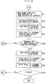
- step S1 If the inspecting device is started, initialization such as memory clear is performed (step S1). If the specifications of the connector C to be inspected are inputted through the keyboard KB (step S2), inspection conditions A or B including image regions to be inspected (Q2, Q4, ... in Fig. 7), the order of processing of the image regions Q2, Q4, ..., and judgment conditions in each of the image regions Q2, Q4, ... are set in response to the input on the basis of the data previously stored in the ROM (steps S4 and S5).
- the inspection conditions A are set if the similar specifications do not exist, while the inspection conditions B are set if the similar specifications exist.
- image regions image regions Q1 and Q3 in Fig. 7 associated with the terminal containing holes C2b each set so as to avoid containing a terminal are excluded from the order of processing.
- the image regions (Q1 and Q3 in Fig. 7) associated with the terminal containing holes C2b each set so as to avoid a containing terminal are set as image regions to be inspected, and judgment conditions that it is accepted that no terminals T are contained are set in the above described image regions associated with the terminal containing holes C2b each set so as to avoid containing a terminal.
- the connector C is set on the mounting plate 20 along the above described cursors 31 and 33, the connector C is detected by the connecting element detecting sensors S1 to S4, the light irradiating device 50, the television camera 70 and the like are started by the computer 80 receiving detection signals, and an image signal obtained by imaging using the television camera 70 is inputted as image data converted into a digital signal (steps S6 to S7). At this time, the image signal is also inputted to the VTR 100.
- a predetermined portion of the inputted image data is binary-coded (step S8), one external shape contour segment CL of the housing CH of the connector C, for example, is extracted on the basis of the binary-coded data (step S9), and a plurality of image regions to be inspected Q2, Q4, ... are set on the basis of the coordinates of the contour segment CL (step S10).
- Each of the image regions Q2 and Q4 to be inspected is then binary-coded for each pixel (step S11), one region to be inspected is divided into a portion occupied by the terminal and the remaining portion on the basis of the binary-coded data, and the number of pixels in the portion occupied by the terminal is compared with the number of pixels in the entire region to be inspected to find the percentage of the area of the portion occupied by the terminal (step S12).
- the found percentage is compared with the above described judgment conditions to judge whether or not the percentage satisfies the judgment conditions for each image region to be inspected (step S13), and the result of the judgment is stored in the RAM (step S14).
- step S15 Processing in the steps S10 to S13 is performed with respect to all image regions to be inspected, to terminate all processing with respect to all the image regions to be inspected Q2, Q4, ... (step S15). If any one of the results of the judgment for the regions to be inspected Q2, Q4, ... is bad, it is judged that the connector C is rejected (step S16). The result of the judgment and information related thereto are outputted to the monitor television 90 (step S17), and the result of the judgment of the connector C is outputted to the sequencer 130 (step S18). So long as the specifications are not changed, the inspecting device waits until the connector C is subsequently set (step S19 and step S6).
- the inspection is made by an image without coming in contact with the terminals T, thereby to make it possible to make the inspection efficiently and with high precision without damaging the terminals T. It is also possible to detect a half-inserted state, which cannot be detected particularly in the conventional method of checking the conduction by bringing a conductor into elastic contact with the terminals. Moreover, the inspecting method according to the present invention is also applicable to a small-sized and multipolar connector C and has wide applicability.
- the processing of the terminal containing holes C2b each set so as to avoid containing a terminal is omitted, thereby to make it possible to improve the processing speed as a whole.
- the terminal containing holes C2b each set so as to avoid containing a terminal under the condition that there exist similar specifications which differ only in that the terminals T are contained in the terminal containing holes C2b each set so as to avoid containing a terminal. Consequently, it is possible to reliably prevent the specifications from being mistaken for the similar specifications.
- regions each sufficiently narrow to find the percentage of the area of the terminal T which is a part of the terminal containing hole are set as image regions Q2, ... to be inspected, thereby to make it possible to improve the processing speed to make the inspection more efficiently.
- the coordinates of the image regions to be inspected Q2, ... are set on the basis of the contour segment CL of the extracted connector C, thereby to make it possible to further improve the inspection precision.
- the positional relationship between the light irradiating section 53 and the television camera 70 is so set that the television camera 70 can avoid regular reflected light from the connecting surface C1.
- Binary-coding processing is performed using diffused reflected light, thereby to make it possible to reliably grasp the contrast of the brightness. As a result, it is possible to reliably determine that the connecting element is rejected, for example, the terminals are not properly mounted.
- the television camera 70 can be also provided in the position where the light irradiating device 50 can image a shadow portion SH formed within the terminal containing hole C2.
- the contrast of the brightness can be obtained more clearly between a portion of the terminal T and the shadow portion SH on the inner surface of the terminal containing hole C2, thereby to make it possible to more reliably determine that the connector C is rejected, for example, the terminal C is not properly mounted.
- the present invention is applicable to another connecting element such as a socket.
- the specifications of the connecting element are inputted using the keyboard KB
- the specifications can be also inputted by reading a bar code attached to the surface of the connecting element using a bar code reader.
- the shift in the position is corrected utilizing a contour segment as a basis
- a pair of projections can be previously provided on the connecting surface C1 to correct the shift in the position utilizing the positions of both the projections (or the holes) as a basis.
Landscapes
- Physics & Mathematics (AREA)
- General Physics & Mathematics (AREA)
- Engineering & Computer Science (AREA)
- Health & Medical Sciences (AREA)
- Computer Vision & Pattern Recognition (AREA)
- Electromagnetism (AREA)
- Toxicology (AREA)
- General Engineering & Computer Science (AREA)
- Manufacturing Of Electrical Connectors (AREA)
- Investigating Materials By The Use Of Optical Means Adapted For Particular Applications (AREA)
- Length Measuring Devices By Optical Means (AREA)
Applications Claiming Priority (3)
| Application Number | Priority Date | Filing Date | Title |
|---|---|---|---|
| JP260232/93 | 1993-10-18 | ||
| JP26023293 | 1993-10-18 | ||
| JP5260232A JP2870379B2 (ja) | 1993-10-18 | 1993-10-18 | 連結素子検査方法およびその装置 |
Publications (2)
| Publication Number | Publication Date |
|---|---|
| EP0649030A1 true EP0649030A1 (fr) | 1995-04-19 |
| EP0649030B1 EP0649030B1 (fr) | 2000-04-05 |
Family
ID=17345194
Family Applications (1)
| Application Number | Title | Priority Date | Filing Date |
|---|---|---|---|
| EP94307635A Expired - Lifetime EP0649030B1 (fr) | 1993-10-18 | 1994-10-18 | Méthode d'inspection d'éléments de connection et dispositif d'inspection d'éléments de connection |
Country Status (4)
| Country | Link |
|---|---|
| US (1) | US5583948A (fr) |
| EP (1) | EP0649030B1 (fr) |
| JP (1) | JP2870379B2 (fr) |
| DE (1) | DE69423840T2 (fr) |
Cited By (1)
| Publication number | Priority date | Publication date | Assignee | Title |
|---|---|---|---|---|
| EP1271164A1 (fr) * | 2001-06-28 | 2003-01-02 | Siemens Automotive EEDS Systems | Contrôle du sertissage de connexion sur un câble plat et dispositif correspondant |
Families Citing this family (45)
| Publication number | Priority date | Publication date | Assignee | Title |
|---|---|---|---|---|
| DE19814687C1 (de) * | 1998-04-01 | 1999-02-18 | Fresenius Medical Care De Gmbh | Dialysegerät mit Vorrichtung zur Herstellung von Dialyselösungen |
| JP2000215961A (ja) * | 1999-01-21 | 2000-08-04 | Harness Syst Tech Res Ltd | 圧接の検査 |
| CN1302280C (zh) * | 2000-04-27 | 2007-02-28 | 精工爱普生株式会社 | 通孔内异物检查方法 |
| US7742071B2 (en) * | 2003-01-23 | 2010-06-22 | Oracle America, Inc. | Methods and apparatus for inspecting centerplane connectors |
| US8029454B2 (en) | 2003-11-05 | 2011-10-04 | Baxter International Inc. | High convection home hemodialysis/hemofiltration and sorbent system |
| US7574035B2 (en) * | 2006-04-07 | 2009-08-11 | United Technologies Corporation | System and method for inspection of hole location on turbine airfoils |
| US8870811B2 (en) | 2006-08-31 | 2014-10-28 | Fresenius Medical Care Holdings, Inc. | Peritoneal dialysis systems and related methods |
| AU2008260230B2 (en) | 2007-05-29 | 2013-09-19 | Fresenius Medical Care Holdings, Inc. | Solutions, dialysates, and related methods |
| US7736328B2 (en) | 2007-07-05 | 2010-06-15 | Baxter International Inc. | Dialysis system having supply container autoconnection |
| US8764702B2 (en) | 2007-07-05 | 2014-07-01 | Baxter International Inc. | Dialysis system having dual patient line connection and prime |
| US7955295B2 (en) | 2007-07-05 | 2011-06-07 | Baxter International Inc. | Fluid delivery system with autoconnect features |
| US8330579B2 (en) | 2007-07-05 | 2012-12-11 | Baxter International Inc. | Radio-frequency auto-identification system for dialysis systems |
| US8157761B2 (en) | 2007-07-05 | 2012-04-17 | Baxter International Inc. | Peritoneal dialysis patient connection system |
| US8496609B2 (en) | 2007-07-05 | 2013-07-30 | Baxter International Inc. | Fluid delivery system with spiked cassette |
| US8197087B2 (en) | 2007-07-05 | 2012-06-12 | Baxter International Inc. | Peritoneal dialysis patient connection system using ultraviolet light emitting diodes |
| US7892197B2 (en) | 2007-09-19 | 2011-02-22 | Fresenius Medical Care Holdings, Inc. | Automatic prime of an extracorporeal blood circuit |
| US8466802B2 (en) * | 2008-03-13 | 2013-06-18 | Siemens Aktiengesellschaft | Manual connecting device |
| US7981281B2 (en) * | 2008-07-09 | 2011-07-19 | Baxter International, Inc. | Dialysis system having regimen generation methodology |
| US8168063B2 (en) * | 2008-07-09 | 2012-05-01 | Baxter International Inc. | Dialysis system having filtering method for determining therapy prescriptions |
| US8057679B2 (en) | 2008-07-09 | 2011-11-15 | Baxter International Inc. | Dialysis system having trending and alert generation |
| US9514283B2 (en) | 2008-07-09 | 2016-12-06 | Baxter International Inc. | Dialysis system having inventory management including online dextrose mixing |
| US8062513B2 (en) | 2008-07-09 | 2011-11-22 | Baxter International Inc. | Dialysis system and machine having therapy prescription recall |
| US9044544B2 (en) | 2008-11-21 | 2015-06-02 | Baxter International Inc. | Dialysis machine having auto-connection system with roller occluder |
| USRE43925E1 (en) * | 2008-11-21 | 2013-01-15 | Industrial Technology Research Institute | Three dimensional profile inspecting apparatus |
| TWI387721B (zh) * | 2008-11-21 | 2013-03-01 | 財團法人工業技術研究院 | 三維形貌檢測裝置 |
| US8282829B2 (en) | 2009-05-20 | 2012-10-09 | Baxter International Inc. | System and method for automated data collection of twenty-four hour ultrafiltration and other patient parameters using wired or wireless technology |
| US8926551B2 (en) * | 2009-07-07 | 2015-01-06 | Baxter Healthcare Inc. | Peritoneal dialysis therapy with large dialysis solution volumes |
| US9930297B2 (en) | 2010-04-30 | 2018-03-27 | Becton, Dickinson And Company | System and method for acquiring images of medication preparations |
| US9772386B2 (en) | 2013-03-15 | 2017-09-26 | Fresenius Medical Care Holdings, Inc. | Dialysis system with sample concentration determination device using magnet and radio frequency coil assemblies |
| US9597439B2 (en) | 2013-03-15 | 2017-03-21 | Fresenius Medical Care Holdings, Inc. | Medical fluid sensing and concentration determination using radio frequency energy and a magnetic field |
| US9566377B2 (en) | 2013-03-15 | 2017-02-14 | Fresenius Medical Care Holdings, Inc. | Medical fluid sensing and concentration determination in a fluid cartridge with multiple passageways, using a radio frequency device situated within a magnetic field |
| US9433718B2 (en) | 2013-03-15 | 2016-09-06 | Fresenius Medical Care Holdings, Inc. | Medical fluid system including radio frequency (RF) device within a magnetic assembly, and fluid cartridge body with one of multiple passageways disposed within the RF device, and specially configured cartridge gap accepting a portion of said RF device |
| US9713664B2 (en) | 2013-03-15 | 2017-07-25 | Fresenius Medical Care Holdings, Inc. | Nuclear magnetic resonance module for a dialysis machine |
| US10286135B2 (en) | 2014-03-28 | 2019-05-14 | Fresenius Medical Care Holdings, Inc. | Measuring conductivity of a medical fluid |
| CA3180239A1 (fr) | 2014-09-08 | 2016-03-17 | Becton, Dickinson And Company | Plateau ameliore pour malaxage pharmaceutique |
| JP6356032B2 (ja) * | 2014-09-29 | 2018-07-11 | 古河電気工業株式会社 | ワイヤハーネスの外観検査装置、ワイヤハーネスの外観検査方法及びワイヤハーネスの外観検査プログラム |
| US10859367B2 (en) | 2015-01-28 | 2020-12-08 | General Electric Company | System and method for locating fluid flow orifices on a component |
| DE102016118981B4 (de) * | 2016-10-06 | 2020-10-08 | Lisa Dräxlmaier GmbH | Verfahren und Vorrichtung zur Bestückung von Steckergehäusen mit konfektionierten Kabelenden eines Kabels |
| US11135345B2 (en) | 2017-05-10 | 2021-10-05 | Fresenius Medical Care Holdings, Inc. | On demand dialysate mixing using concentrates |
| US11504458B2 (en) | 2018-10-17 | 2022-11-22 | Fresenius Medical Care Holdings, Inc. | Ultrasonic authentication for dialysis |
| JP7336285B2 (ja) * | 2019-07-12 | 2023-08-31 | 三菱重工業株式会社 | コネクタ撮影装置および撮影方法 |
| TWI702493B (zh) * | 2019-09-09 | 2020-08-21 | 英業達股份有限公司 | 插槽檢測方法及系統 |
| KR102804913B1 (ko) * | 2020-03-12 | 2025-05-08 | 현대자동차 주식회사 | 헤어핀 권선 타입 고정자 검사 장치 및 방법 |
| CN114519688A (zh) * | 2020-11-17 | 2022-05-20 | 泰科电子(上海)有限公司 | 连接器质量检查方法 |
| CN114543659B (zh) * | 2020-11-26 | 2023-10-20 | 泰科电子(上海)有限公司 | 连接器质量检查方法和系统 |
Citations (4)
| Publication number | Priority date | Publication date | Assignee | Title |
|---|---|---|---|---|
| DE2937929A1 (de) * | 1979-04-25 | 1980-11-06 | Hitachi Ltd | Verfahren und vorrichtung zum pruefen von leiterplatten fuer gedruckte schaltungen |
| EP0429739A1 (fr) * | 1989-11-28 | 1991-06-05 | International Business Machines Corporation | Procédé pour vérification de trous métallisés d'un emballage de circuits intégrés, par photo-émission |
| EP0510887A2 (fr) * | 1991-04-26 | 1992-10-28 | Sharp Kabushiki Kaisha | Procédé et dispositif de détection et d'analyse d'éléments semi-conducteurs défectueux |
| EP0562614A2 (fr) * | 1992-03-26 | 1993-09-29 | Sumitomo Wiring Systems, Ltd. | Procédé et dispositif d'inspection d'une borne sans soudage par le traitement d'images |
Family Cites Families (4)
| Publication number | Priority date | Publication date | Assignee | Title |
|---|---|---|---|---|
| JPS6247093A (ja) * | 1985-08-26 | 1987-02-28 | 日本電気株式会社 | 拡大表示制御回路 |
| US4799268A (en) * | 1985-11-12 | 1989-01-17 | Usm Corporation | Lead sense system for component insertion machine |
| US5220617A (en) * | 1991-09-04 | 1993-06-15 | International Business Machines Corporation | Method and apparatus for object inspection |
| US5353357A (en) * | 1992-12-04 | 1994-10-04 | Philip Morris Incorporated | Methods and apparatus for inspecting the appearance of substantially circular objects |
-
1993
- 1993-10-18 JP JP5260232A patent/JP2870379B2/ja not_active Expired - Fee Related
-
1994
- 1994-10-12 US US08/321,671 patent/US5583948A/en not_active Expired - Fee Related
- 1994-10-18 EP EP94307635A patent/EP0649030B1/fr not_active Expired - Lifetime
- 1994-10-18 DE DE69423840T patent/DE69423840T2/de not_active Expired - Fee Related
Patent Citations (4)
| Publication number | Priority date | Publication date | Assignee | Title |
|---|---|---|---|---|
| DE2937929A1 (de) * | 1979-04-25 | 1980-11-06 | Hitachi Ltd | Verfahren und vorrichtung zum pruefen von leiterplatten fuer gedruckte schaltungen |
| EP0429739A1 (fr) * | 1989-11-28 | 1991-06-05 | International Business Machines Corporation | Procédé pour vérification de trous métallisés d'un emballage de circuits intégrés, par photo-émission |
| EP0510887A2 (fr) * | 1991-04-26 | 1992-10-28 | Sharp Kabushiki Kaisha | Procédé et dispositif de détection et d'analyse d'éléments semi-conducteurs défectueux |
| EP0562614A2 (fr) * | 1992-03-26 | 1993-09-29 | Sumitomo Wiring Systems, Ltd. | Procédé et dispositif d'inspection d'une borne sans soudage par le traitement d'images |
Cited By (2)
| Publication number | Priority date | Publication date | Assignee | Title |
|---|---|---|---|---|
| EP1271164A1 (fr) * | 2001-06-28 | 2003-01-02 | Siemens Automotive EEDS Systems | Contrôle du sertissage de connexion sur un câble plat et dispositif correspondant |
| FR2826729A1 (fr) * | 2001-06-28 | 2003-01-03 | Siemens Automotive Eeds System | Controle de sertissage de connexion sur un cable plat et dispositif correspondant |
Also Published As
| Publication number | Publication date |
|---|---|
| EP0649030B1 (fr) | 2000-04-05 |
| US5583948A (en) | 1996-12-10 |
| DE69423840D1 (de) | 2000-05-11 |
| JPH07114968A (ja) | 1995-05-02 |
| DE69423840T2 (de) | 2000-10-12 |
| JP2870379B2 (ja) | 1999-03-17 |
Similar Documents
| Publication | Publication Date | Title |
|---|---|---|
| EP0649030B1 (fr) | Méthode d'inspection d'éléments de connection et dispositif d'inspection d'éléments de connection | |
| JP2624054B2 (ja) | 電線皮剥ぎ状態検査方法 | |
| EP0195161A2 (fr) | Appareil et procédé d'inspection automatique d'objets et d'identification ou de reconnaissance de leurs parties connues et inconnues, y compris des défauts et similaires | |
| US4642813A (en) | Electro-optical quality control inspection of elements on a product | |
| KR102191704B1 (ko) | 머신비전기반 하네스 불량 검사방법 | |
| EP0472041A2 (fr) | Procédé et dispositif pour détecter des déformations de conducteurs d'un dispositif semi-conducteur | |
| EP0242045B1 (fr) | Procédé pour la détermination de dimensions | |
| JP2002107302A (ja) | 端子金具の検査方法及び検査装置 | |
| JPS6042884B2 (ja) | Icリ−ド曲り検査装置 | |
| JPH05272939A (ja) | 圧着端子画像処理検査における照明方法及び画像処理方法 | |
| US5570191A (en) | Identification of connector terminals | |
| KR0176497B1 (ko) | 전자부품 실장기의 노즐 타입 인식방법 | |
| JPH0794971B2 (ja) | 断面形状検知方法 | |
| JP2792362B2 (ja) | 圧着端子の圧着検査方法 | |
| JP2009103661A (ja) | 基板検査装置 | |
| KR19980039100A (ko) | 부품의 클린칭 방향을 이용한 미삽 검사장치 및 방법 | |
| JPH05275900A (ja) | 部品リードの実装状態検査方法 | |
| JPH09178445A (ja) | 電子部品の端子曲がり検査装置 | |
| KR100206360B1 (ko) | 인쇄회로기판의 미삽검사방법 | |
| JPH06204700A (ja) | チップ部品実装検査装置 | |
| JPH0961116A (ja) | 物品検査方法及び装置 | |
| JP2601232B2 (ja) | Icリードずれ検査装置 | |
| JP2003215061A (ja) | ピン検査装置およびピン検査方法およびピン製品およびピン製品の製造方法 | |
| JPH05249043A (ja) | 圧着端子画像処理検査における照明方法 | |
| JPH11120355A (ja) | 画像処理方法 |
Legal Events
| Date | Code | Title | Description |
|---|---|---|---|
| PUAI | Public reference made under article 153(3) epc to a published international application that has entered the european phase |
Free format text: ORIGINAL CODE: 0009012 |
|
| AK | Designated contracting states |
Kind code of ref document: A1 Designated state(s): DE GB |
|
| 17P | Request for examination filed |
Effective date: 19950627 |
|
| GRAG | Despatch of communication of intention to grant |
Free format text: ORIGINAL CODE: EPIDOS AGRA |
|
| GRAG | Despatch of communication of intention to grant |
Free format text: ORIGINAL CODE: EPIDOS AGRA |
|
| GRAH | Despatch of communication of intention to grant a patent |
Free format text: ORIGINAL CODE: EPIDOS IGRA |
|
| 17Q | First examination report despatched |
Effective date: 19990826 |
|
| GRAH | Despatch of communication of intention to grant a patent |
Free format text: ORIGINAL CODE: EPIDOS IGRA |
|
| GRAA | (expected) grant |
Free format text: ORIGINAL CODE: 0009210 |
|
| AK | Designated contracting states |
Kind code of ref document: B1 Designated state(s): DE GB |
|
| REF | Corresponds to: |
Ref document number: 69423840 Country of ref document: DE Date of ref document: 20000511 |
|
| EN | Fr: translation not filed | ||
| PLBE | No opposition filed within time limit |
Free format text: ORIGINAL CODE: 0009261 |
|
| STAA | Information on the status of an ep patent application or granted ep patent |
Free format text: STATUS: NO OPPOSITION FILED WITHIN TIME LIMIT |
|
| 26N | No opposition filed | ||
| REG | Reference to a national code |
Ref country code: GB Ref legal event code: IF02 |
|
| PGFP | Annual fee paid to national office [announced via postgrant information from national office to epo] |
Ref country code: GB Payment date: 20021016 Year of fee payment: 9 |
|
| PGFP | Annual fee paid to national office [announced via postgrant information from national office to epo] |
Ref country code: DE Payment date: 20021024 Year of fee payment: 9 |
|
| PG25 | Lapsed in a contracting state [announced via postgrant information from national office to epo] |
Ref country code: GB Free format text: LAPSE BECAUSE OF NON-PAYMENT OF DUE FEES Effective date: 20031018 |
|
| PG25 | Lapsed in a contracting state [announced via postgrant information from national office to epo] |
Ref country code: DE Free format text: LAPSE BECAUSE OF NON-PAYMENT OF DUE FEES Effective date: 20040501 |
|
| GBPC | Gb: european patent ceased through non-payment of renewal fee |
Effective date: 20031018 |