EP0651489B1 - Dispositif de détection d'anomalie d'un relais - Google Patents
Dispositif de détection d'anomalie d'un relais Download PDFInfo
- Publication number
- EP0651489B1 EP0651489B1 EP94117208A EP94117208A EP0651489B1 EP 0651489 B1 EP0651489 B1 EP 0651489B1 EP 94117208 A EP94117208 A EP 94117208A EP 94117208 A EP94117208 A EP 94117208A EP 0651489 B1 EP0651489 B1 EP 0651489B1
- Authority
- EP
- European Patent Office
- Prior art keywords
- motor
- controller
- relay
- diodes
- detection signal
- Prior art date
- Legal status (The legal status is an assumption and is not a legal conclusion. Google has not performed a legal analysis and makes no representation as to the accuracy of the status listed.)
- Expired - Lifetime
Links
- 230000005856 abnormality Effects 0.000 title claims description 21
- 238000001514 detection method Methods 0.000 claims description 14
- 238000010276 construction Methods 0.000 description 7
- 238000010586 diagram Methods 0.000 description 6
- 230000005284 excitation Effects 0.000 description 6
- 230000008018 melting Effects 0.000 description 6
- 238000002844 melting Methods 0.000 description 6
- 230000002159 abnormal effect Effects 0.000 description 3
- 230000000694 effects Effects 0.000 description 1
- 230000004048 modification Effects 0.000 description 1
- 238000012986 modification Methods 0.000 description 1
Images



Classifications
-
- H—ELECTRICITY
- H02—GENERATION; CONVERSION OR DISTRIBUTION OF ELECTRIC POWER
- H02H—EMERGENCY PROTECTIVE CIRCUIT ARRANGEMENTS
- H02H7/00—Emergency protective circuit arrangements specially adapted for specific types of electric machines or apparatus or for sectionalised protection of cable or line systems, and effecting automatic switching in the event of an undesired change from normal working conditions
- H02H7/08—Emergency protective circuit arrangements specially adapted for specific types of electric machines or apparatus or for sectionalised protection of cable or line systems, and effecting automatic switching in the event of an undesired change from normal working conditions for dynamo-electric motors
- H02H7/0833—Emergency protective circuit arrangements specially adapted for specific types of electric machines or apparatus or for sectionalised protection of cable or line systems, and effecting automatic switching in the event of an undesired change from normal working conditions for dynamo-electric motors for electric motors with control arrangements
- H02H7/0844—Fail safe control, e.g. by comparing control signal and controlled current, isolating motor on commutation error
Definitions
- the present invention relates to a relay abnormality detecting device for detecting an abnormality in relays for driving a motor such as an automotive door lock motor, an automotive power window motor, and an automotive sun roof motor.
- a switching control signal output terminal O1 or O2 of the controller 1 outputs a high-level (referred to as "H" hereinafter) switching control signal to a base of an first NPN transistor Q1 serving as a switching element for forward rotation or to a base of a second NPN transistor Q2 serving as a switching element for backward rotation, to turn on the transistor Q1 or Q2.
- H high-level
- a c-contact T1 of the first relay RL1 is switched from a normally-closed terminal to a normally-open terminal.
- the transistor Q2 turns on, current flows from the battery +B through the fuse F2 to a relay coil C2 of a second motor driving relay RL2 to excite the relay coil C2.
- a c-contact T2 of the second relay RL2 is switched from a normally-closed terminal to a normally-open terminal.
- a motor driving portion 2 for driving a motor M is formed by the transistors Q1, Q2, and the relays RL1, RL2.
- Switching of the c-contact T1 to the normally-open terminal by excitation of the first relay RL1 causes current from the battery +B to flow to a ground through a fuse F1, the normally-open terminal and a common terminal of the c-contact T1 of the first relay RL1, the motor M, and a common terminal and the normally-closed terminal of the c-contact T2 of the second relay RL2.
- the current flows through the motor M in a direction of forward rotation to forwardly rotate the motor M.
- switching of the c-contact T2 to the normally-open terminal by excitation of the second relay RL2 causes current from the battery +B to flow to a ground through the fuse F2, the normally-open terminal and a common terminal of the c-contact T2 of the second relay RL2, the motor M, and a common terminal and the normally-closed terminal of the c-contact T1 of the first relay RL1.
- the current flows through the motor M in a direction of backward rotation to backwardly rotate the motor M.
- the switching control signal output terminal O1 or O2 of the controller 1 outputs an "H" switching control signal to the base of the first NPN transistor Q1 serving as the switching element for forward rotation or to the base of the second NPN transistor Q2 serving as the switching element for backward rotation, to turn on the transistor Q1 or Q2.
- the first transistor Q1 turns on, current flows from the battery +B to the relay coil C1 of the first motor driving relay RL1 to excite the relay coil C1. Then the c-contact T1 of the first relay RL1 is switched from the normally-closed terminal to the normally-open terminal.
- the motor driving portion 2 for driving the motor M is formed by the transistors Q1, Q2 and the relays RL1, RL2.
- Switching of the c-contact T1 to the normally-open terminal by excitation of the first relay RL1 causes current from the battery +B to flow to the ground through the normally-open terminal and common terminal of the c-contact T1 of the first relay RL1, the motor M, and the common terminal and normally-closed terminal of the c-contact T2 of the second relay RL2.
- the current flows through the motor M in the direction of forward rotation to forwardly rotate the motor M.
- Switching of the c-contact T2 to the normally-open terminal by excitation of the second relay RL2 causes current from the battery +B to flow to the ground through the normally-open terminal and common terminal of the c-contact T2 of the second relay RL2, the motor M, and the common terminal and normally-closed terminal of the c-contact T1 of the second relay RL1.
- the current flows though the motor M in the direction of backward rotation to backwardly rotate the motor M.
- opposite ends of the motor M are connected to detection signal input terminals I1 and I2 of the controller 1 through diodes D1 and D2, respectively.
- the input terminals I1 and I2 are grounded through pull-down resistors R1 and R2, respectively.
- the diodes D1, D2 and the resistors R1, R2 form a signal detecting portion 3.
- a third relay RL3 for interrupting the power supply is formed in a current-flow path between the battery +B and the motor M so as to prevent damages to the motor M when current keeps flowing through the motor M after the excitation of the relays RL1 and RL2 is released because of the occurrence of an abnormality such as melting of the relays RL1 and RL2.
- a cutoff control signal at a low level (referred to as "L" hereinafter) from a cutoff control signal output terminal O3 of the controller 1 causes a third NPN transistor Q3 to be switched from on to off, which in turn interrupts a current flow from the battery +B to a relay coil C3 of the third relay RL3 to turn off a relay contact T3.
- the turning off of the relay contact T3 interrupts the current-flow path from the battery +B to the motor M to force the motor M to stop.
- the output terminal O3 of the controller 1 is held high as shown in Fig. 7E and the third relay RL3 is kept excited to hold the relay contact T3 in its on state.
- the output terminal O1 of the controller 1 is switched from H to L as shown in Fig. 7A because of the occurrence of an abnormality such as melting of the first relay RL1, the continuous application of the "H" signal to the input terminal I1 as shown in Fig.
- the transistor Q3 and the third relay RL3 are required to force the motor M to stop when the motor driving relays RL1 and RL2 are abnormal. This has added to the number of components, complexity of construction, and costs.
- the present invention is intended for a device for detecting an abnormality in relays for driving a motor including an automotive door lock motor, an automotive power window motor, and an automotive sun roof motor.
- the device comprises: a power supply; a motor driving portion including a first switching element for forward rotation, a second switching element for backward rotation, a first motor driving relay for forward rotation operated in response to turning-on of the first switching element, and a second motor driving relay for backward rotation operated in response to turning-on of the second switching element, the motor driving portion passing current from the power supply through the motor in directions of the forward and backward rotations by operation of the first and second relays, respectively, to drive the motor; an input portion for providing a forward rotation command and a backward rotation command; a controller for outputting a switching control signal to the first and second switching elements in response to the forward and backward rotation commands, respectively; and a signal detecting portion for detecting current through the motor to output a detection signal to the controller, wherein the controller senses a current flow through the motor
- the controller provides the same potential across the motor by turning on the switching elements of the motor driving portion, thereby to reliably stop the motor. Therefore, the motor is stopped under abnormal conditions of the relays by a simplified, less costly construction without the conventionally complicated, costly construction.
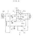
- Fig. 1 is a circuit diagram of a first preferred embodiment according to the present invention.
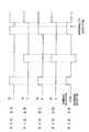
- Figs. 2A to 2E illustrate operation of the first preferred embodiment.
- Fig. 1 differs from that of Fig. 6 in that the third transistor Q3 and the third relay RL3 of Fig. 6 are not provided and that the controller 1 has a function to output an "H" switching control signal simultaneously at the output terminals O1 and O2 when current from the battery +B continues flowing through the motor M because of an abnormality such as melting of the relays RL1 and RL2 and an "H" detection signal is kept being applied to the input terminals I1 and I2 even though the "H" switching control signal stops being outputted to the transistors Q1 and Q2.
- the controller 1 causes the transistors Q1 and Q2 to turn on and, accordingly, the same potential across the motor M stops the motor M. This eliminates the need for the conventional power supply interrupting relays and transistors and facilitates the construction. Detection of the abnormality in the relays and stop of the motor M are achieved by the simplified, less expensive device.
- Fig. 3 is a circuit diagram of a second preferred embodiment according to the present invention.
- Figs. 4A to 4D illustrate operation of the second preferred embodiment.
- the second preferred embodiment differs from the first preferred embodiment in that the resistor R2 is not provided and in that the cathode of the diode D2 and the cathode of the diode D1 are commonly connected to the detection signal input terminal I1 of the controller 1.
- the second preferred embodiment provides effects similar to those of the first preferred embodiment and involves the need for fewer components than the first preferred embodiment because of the absence of the resistor R2, allowing more simplified and less costly construction.
- the switching elements of the motor driving portion are not limited to the above stated transistors.
- the signal detecting portion is not limited to that of the preferred embodiments.
Landscapes
- Control Of Direct Current Motors (AREA)
Claims (5)
- Dispositif de détection d'une anomalie de relais (RL1, RL2) destinés à attaquer un moteur (M) comprenant un moteur de verrouillage de portes d'automobile, un moteur de vitre à commande électrique d'automobile, et un moteur de toit ouvrant d'automobile, ledit dispositif comprenant :une alimentation (+B) ;une partie d'attaque de moteur comprenant un premier élément (Q1) de commutation pour rotation vers l'avant, un second élément (Q2) de commutation pour rotation vers l'arrière, un premier relais (RL1) d'attaque de moteur pour rotation vers l'avant, excité en réponse au déblocage dudit premier élément (Q1) de commutation, et un second relais (RL2) d'attaque de moteur pour rotation vers l'arrière, excité en réponse au déblocage dudit second élément (Q2) de commutation, ladite partie d'attaque de moteur faisant passer du courant de ladite alimentation (+B) par ledit moteur (M) dans les sens des rotations vers l'avant et vers l'arrière par l'excitation, respectivement, desdits premier et second relais (RL1, RL2) pour attaquer ledit moteur (M) ;une partie (SW) d'entrée destinée à fournir une instruction de rotation vers l'avant et une instruction de rotation vers l'arrière ;un régisseur (1) destiné à délivrer un signal de commande de commutation respectivement auxdits premier et second éléments (Q1, Q2) de commutation, en réponse auxdites instructions de rotation vers l'avant et vers l'arrière ; etune partie (D1, D2, R1, R2 ; D1, D2, R1) de détection de signal destinée à détecter du courant passant par ledit moteur pour délivrer un signal de détection audit régisseur (1) ;dans lequel ledit régisseur (1) capte un passage de courant passant par ledit moteur (M) lorsque lesdits premier et second éléments (Q1, Q2) de commutation sont bloqués sur la base dudit signal de détection pour détecter une anomalie desdits relais (RL1, RL2) d'attaque de moteur, et ledit régisseur (1) rend conducteurs lesdits premier et second éléments (Q1, Q2) de commutation en délivrant ledit signal de commande de commutation auxdits premier et second éléments (Q1, Q2) de commutation pour fournir le même potentiel aux bornes dudit moteur (M).
- Dispositif selon la revendication 1, dans lequel lesdits premier et second éléments (Q1, Q2) de commutation comprennent des transistors.
- Dispositif selon la revendication 1, dans lequel ladite partie (SW) d'entrée comprend un commutateur.
- Dispositif selon la revendication 1, dans lequel :ladite partie de détection de signal comprend deux diodes (D1, D2) dont les anodes sont respectivement connectées aux extrémités opposées dudit moteur (M), et deux résistances (R1, R2) connectées, respectivement, entre les cathodes desdites deux diodes (D1, D2) et la masse ; et dans lequellesdites diodes (D1, D2) se laissent traverser par une partie du courant passant par ledit moteur (M) dans les sens des rotations vers l'avant et vers l'arrière, et des tensions aux bornes desdites deux résistances (R1, R2) sont appliquées respectivement à deux bornes (I1, I2) d'entrée de signal de détection dudit régisseur (1) sous la forme dudit signal de détection.
- Dispositif selon la revendication 1, dans lequel :ladite partie de détection de signal comprend deux diodes (D1, D2) dont les anodes sont respectivement connectées aux extrémités opposées dudit moteur (M), et une résistance (R1) connectée entre les cathodes desdites diodes (D1, D2) et la masse ; et dans lequellesdites diodes (D1, D2) se laissent traverser par une partie du courant passant par ledit moteur (M) dans les sens des rotations vers l'avant et vers l'arrière, et une tension aux bornes de ladite résistance (R1) est appliquée à une borne (Il) d'entrée de signal de détection dudit régisseur (1) sous la forme dudit signal de détection.
Applications Claiming Priority (2)
| Application Number | Priority Date | Filing Date | Title |
|---|---|---|---|
| JP1993063607U JP2594573Y2 (ja) | 1993-11-02 | 1993-11-02 | リレーの異常検知装置 |
| JP63607/93 | 1993-11-02 |
Publications (2)
| Publication Number | Publication Date |
|---|---|
| EP0651489A1 EP0651489A1 (fr) | 1995-05-03 |
| EP0651489B1 true EP0651489B1 (fr) | 1999-03-24 |
Family
ID=13234152
Family Applications (1)
| Application Number | Title | Priority Date | Filing Date |
|---|---|---|---|
| EP94117208A Expired - Lifetime EP0651489B1 (fr) | 1993-11-02 | 1994-10-31 | Dispositif de détection d'anomalie d'un relais |
Country Status (4)
| Country | Link |
|---|---|
| US (1) | US5568025A (fr) |
| EP (1) | EP0651489B1 (fr) |
| JP (1) | JP2594573Y2 (fr) |
| DE (1) | DE69417344T2 (fr) |
Families Citing this family (22)
| Publication number | Priority date | Publication date | Assignee | Title |
|---|---|---|---|---|
| DE19513157A1 (de) * | 1995-04-07 | 1996-10-10 | Bosch Gmbh Robert | Vorrichtung zum Betreiben eines Verstellantriebs |
| BR9811960A (pt) * | 1997-08-22 | 2000-08-15 | Bosch Gmbh Robert | Processo para reconhecer erros de conexão de um primeiro relê |
| JPH11206182A (ja) * | 1998-01-14 | 1999-07-30 | Omron Corp | モータ駆動装置及びパワーウインド装置 |
| US5944635A (en) * | 1998-01-28 | 1999-08-31 | Digital Concepts Of Missouri, Inc. | Safety shutdown and latch off |
| DK175056B1 (da) * | 1998-02-27 | 2004-05-10 | Linak As | Styring til elmotorer, navnlig i lineære aktuatorer |
| KR100375066B1 (ko) * | 2001-04-19 | 2003-03-07 | 엘지산전 주식회사 | 계전기의 바이털 접점 감지 장치 |
| NO316049B1 (no) | 2002-10-30 | 2003-12-01 | Sleipner Motor As | Fremgangsmåte og styresystem for styring av elektromotorer |
| US7360848B2 (en) * | 2004-04-16 | 2008-04-22 | Advics Co., Ltd. | Parallel relay circuit for hydraulic braking device |
| US20060087784A1 (en) * | 2004-10-27 | 2006-04-27 | Dell Products L.P. | Over current protection device selection using active voltage sensing circuit |
| EP1810396A1 (fr) * | 2004-11-05 | 2007-07-25 | Labofa Munch A/S | Mecanisme d'elevation et d'abaissement d'un plateau de table |
| WO2006063303A1 (fr) * | 2004-12-09 | 2006-06-15 | Won-Door Corporation | Procede et appareil de commande de moteur utilisant des relais |
| DE102006036956B4 (de) * | 2005-10-31 | 2010-10-14 | Diehl Ako Stiftung & Co. Kg | Steuereinheit für einen elektrischen Antriebsmotor |
| DE102008011495B4 (de) * | 2008-02-19 | 2011-09-22 | E.G.O. Control Systems Gmbh | Steuergerät für ein Haushaltsgerät, Haushaltsgerät und zugehöriges Verfahren |
| JP4631924B2 (ja) * | 2008-04-16 | 2011-02-16 | トヨタ自動車株式会社 | 駆動装置およびこれを搭載するハイブリッド車並びに駆動装置の制御方法 |
| JP5661276B2 (ja) * | 2009-12-24 | 2015-01-28 | ダイヤモンド電機株式会社 | モータ制御装置 |
| CN102874124B (zh) * | 2011-07-14 | 2014-09-17 | 北汽福田汽车股份有限公司 | 电动汽车的电池的继电器控制策略及装置 |
| JP2015085739A (ja) * | 2013-10-29 | 2015-05-07 | アイシン精機株式会社 | 車両用開閉部材の制御装置及び制御方法 |
| JP6279364B2 (ja) * | 2014-03-13 | 2018-02-14 | アスモ株式会社 | モータ制御装置 |
| JP6471475B2 (ja) * | 2014-11-26 | 2019-02-20 | アイシン精機株式会社 | 車両用開閉部材の制御装置及び制御方法 |
| US10744963B2 (en) * | 2015-11-17 | 2020-08-18 | Autonetworks Technologies, Ltd. | Charge/discharge device |
| KR101972877B1 (ko) * | 2017-08-28 | 2019-04-29 | 동아전장주식회사 | 릴레이 내장형 모터 |
| KR102291762B1 (ko) * | 2017-11-07 | 2021-09-03 | 주식회사 엘지에너지솔루션 | 릴레이 진단 회로 |
Family Cites Families (12)
| Publication number | Priority date | Publication date | Assignee | Title |
|---|---|---|---|---|
| JPS53115540A (en) * | 1977-03-19 | 1978-10-09 | Kazuyoshi Ozaki | Opening*closing end controlling apparatus for automatic door |
| US4300085A (en) * | 1979-07-18 | 1981-11-10 | Hitachi Koki Company, Limited | Failure detection method and circuit for stepping motors |
| JPS62153736U (fr) * | 1986-03-20 | 1987-09-29 | ||
| US5012165A (en) * | 1986-11-04 | 1991-04-30 | Lautzenhiser Lloyd L | Conveyance with electronic control for left and right motors |
| US4972129A (en) * | 1988-07-18 | 1990-11-20 | Nippon Seiko Kabushiki Kaisha | Passive seat belt apparatus |
| DE3833702A1 (de) * | 1988-10-04 | 1990-04-05 | Ako Werke Gmbh & Co | Steuerschaltung eines universalmotors |
| JPH02148529A (ja) * | 1988-11-29 | 1990-06-07 | Matsushita Electric Ind Co Ltd | リレー監視回路 |
| JPH0345098U (fr) * | 1989-09-11 | 1991-04-25 | ||
| US5065079A (en) * | 1990-10-23 | 1991-11-12 | Tachi-S Co., Ltd. | Method and apparatus for controlling lumbar support device |
| US5136221A (en) * | 1991-04-16 | 1992-08-04 | Tachi-S Co. Ltd | Method and device for controlling a powered automotive seat of rotatable type |
| JPH0530767A (ja) * | 1991-07-17 | 1993-02-05 | Asmo Co Ltd | 自動停止制御装置 |
| JP2721056B2 (ja) * | 1991-08-29 | 1998-03-04 | 株式会社クボタ | 電動アクチュエータの非常停止装置 |
-
1993
- 1993-11-02 JP JP1993063607U patent/JP2594573Y2/ja not_active Expired - Fee Related
-
1994
- 1994-10-26 US US08/329,254 patent/US5568025A/en not_active Expired - Lifetime
- 1994-10-31 DE DE69417344T patent/DE69417344T2/de not_active Expired - Fee Related
- 1994-10-31 EP EP94117208A patent/EP0651489B1/fr not_active Expired - Lifetime
Also Published As
| Publication number | Publication date |
|---|---|
| JP2594573Y2 (ja) | 1999-04-26 |
| EP0651489A1 (fr) | 1995-05-03 |
| JPH0729732U (ja) | 1995-06-02 |
| DE69417344T2 (de) | 1999-10-14 |
| US5568025A (en) | 1996-10-22 |
| DE69417344D1 (de) | 1999-04-29 |
Similar Documents
| Publication | Publication Date | Title |
|---|---|---|
| US5568025A (en) | Abnormally detecting device for relay | |
| EP0522492B1 (fr) | Direction assistée électriquement | |
| US5530788A (en) | Electric motor drive control apparatus | |
| EP0938118B1 (fr) | Unite de commande pour relais | |
| JPH0685636B2 (ja) | 電気調節装置の安全装置 | |
| US6744609B2 (en) | Motor control circuit having motor protective circuit | |
| US20050218904A1 (en) | Fault detection circuit for a driver circuit | |
| JPH1042586A (ja) | モータ駆動回路 | |
| JP2003308123A (ja) | 電源保護回路 | |
| JP2002037032A (ja) | ワイパ制御装置 | |
| JP2005318791A (ja) | 駆動装置の故障検出回路 | |
| JPH0473327B2 (fr) | ||
| JPH06215676A (ja) | リレー制御回路 | |
| KR100316933B1 (ko) | 솔레노이드 구동 회로 | |
| JP2728902B2 (ja) | 電源遮断装置 | |
| KR20000030981A (ko) | 과부하시 역 회전 하는 자동차용 레귤레이터 모터 및 그 제어방법 | |
| KR200183344Y1 (ko) | 와이퍼 구동회로 | |
| JPH1155847A (ja) | 車両負荷制御装置 | |
| JP3236773B2 (ja) | 給電機能付制御装置 | |
| JP4041981B2 (ja) | 駆動装置 | |
| JPH08306290A (ja) | モータ用リレーの駆動方法及びその装置 | |
| JPH0735085Y2 (ja) | パワーウインドレギュレータの制御装置 | |
| JPH07101998B2 (ja) | モ−タ駆動回路 | |
| JP3248732B2 (ja) | リレー駆動回路 | |
| JPH06283986A (ja) | パワートランジスタ保護回路 |
Legal Events
| Date | Code | Title | Description |
|---|---|---|---|
| PUAI | Public reference made under article 153(3) epc to a published international application that has entered the european phase |
Free format text: ORIGINAL CODE: 0009012 |
|
| AK | Designated contracting states |
Kind code of ref document: A1 Designated state(s): DE FR GB |
|
| 17P | Request for examination filed |
Effective date: 19950405 |
|
| GRAG | Despatch of communication of intention to grant |
Free format text: ORIGINAL CODE: EPIDOS AGRA |
|
| 17Q | First examination report despatched |
Effective date: 19980420 |
|
| GRAG | Despatch of communication of intention to grant |
Free format text: ORIGINAL CODE: EPIDOS AGRA |
|
| GRAH | Despatch of communication of intention to grant a patent |
Free format text: ORIGINAL CODE: EPIDOS IGRA |
|
| GRAH | Despatch of communication of intention to grant a patent |
Free format text: ORIGINAL CODE: EPIDOS IGRA |
|
| GRAA | (expected) grant |
Free format text: ORIGINAL CODE: 0009210 |
|
| AK | Designated contracting states |
Kind code of ref document: B1 Designated state(s): DE FR GB |
|
| REF | Corresponds to: |
Ref document number: 69417344 Country of ref document: DE Date of ref document: 19990429 |
|
| ET | Fr: translation filed | ||
| PLBE | No opposition filed within time limit |
Free format text: ORIGINAL CODE: 0009261 |
|
| STAA | Information on the status of an ep patent application or granted ep patent |
Free format text: STATUS: NO OPPOSITION FILED WITHIN TIME LIMIT |
|
| 26N | No opposition filed | ||
| REG | Reference to a national code |
Ref country code: GB Ref legal event code: IF02 |
|
| PGFP | Annual fee paid to national office [announced via postgrant information from national office to epo] |
Ref country code: FR Payment date: 20041008 Year of fee payment: 11 |
|
| PGFP | Annual fee paid to national office [announced via postgrant information from national office to epo] |
Ref country code: GB Payment date: 20041027 Year of fee payment: 11 |
|
| PGFP | Annual fee paid to national office [announced via postgrant information from national office to epo] |
Ref country code: DE Payment date: 20041028 Year of fee payment: 11 |
|
| PG25 | Lapsed in a contracting state [announced via postgrant information from national office to epo] |
Ref country code: GB Free format text: LAPSE BECAUSE OF NON-PAYMENT OF DUE FEES Effective date: 20051031 |
|
| PG25 | Lapsed in a contracting state [announced via postgrant information from national office to epo] |
Ref country code: DE Free format text: LAPSE BECAUSE OF NON-PAYMENT OF DUE FEES Effective date: 20060503 |
|
| GBPC | Gb: european patent ceased through non-payment of renewal fee |
Effective date: 20051031 |
|
| PG25 | Lapsed in a contracting state [announced via postgrant information from national office to epo] |
Ref country code: FR Free format text: LAPSE BECAUSE OF NON-PAYMENT OF DUE FEES Effective date: 20060630 |
|
| REG | Reference to a national code |
Ref country code: FR Ref legal event code: ST Effective date: 20060630 |