EP0657234A1 - Moule pour la coulée de la partie centrale latérale d'un bloc-moteur - Google Patents
Moule pour la coulée de la partie centrale latérale d'un bloc-moteur Download PDFInfo
- Publication number
- EP0657234A1 EP0657234A1 EP94113530A EP94113530A EP0657234A1 EP 0657234 A1 EP0657234 A1 EP 0657234A1 EP 94113530 A EP94113530 A EP 94113530A EP 94113530 A EP94113530 A EP 94113530A EP 0657234 A1 EP0657234 A1 EP 0657234A1
- Authority
- EP
- European Patent Office
- Prior art keywords
- mold
- engine block
- hole
- cylinders
- inner mold
- Prior art date
- Legal status (The legal status is an assumption and is not a legal conclusion. Google has not performed a legal analysis and makes no representation as to the accuracy of the status listed.)
- Granted
Links
- 238000005266 casting Methods 0.000 title claims abstract description 16
- 238000002485 combustion reaction Methods 0.000 claims abstract description 19
- 239000000498 cooling water Substances 0.000 claims description 4
- 230000009467 reduction Effects 0.000 abstract description 3
- 238000004512 die casting Methods 0.000 description 4
- 230000006872 improvement Effects 0.000 description 4
- 229910000831 Steel Inorganic materials 0.000 description 3
- 239000000463 material Substances 0.000 description 3
- 229910052751 metal Inorganic materials 0.000 description 3
- 239000002184 metal Substances 0.000 description 3
- 230000002093 peripheral effect Effects 0.000 description 3
- 239000010959 steel Substances 0.000 description 3
- 230000004048 modification Effects 0.000 description 2
- 238000012986 modification Methods 0.000 description 2
- 229910000838 Al alloy Inorganic materials 0.000 description 1
- 239000004809 Teflon Substances 0.000 description 1
- 229920006362 Teflon® Polymers 0.000 description 1
- 229910052782 aluminium Inorganic materials 0.000 description 1
- XAGFODPZIPBFFR-UHFFFAOYSA-N aluminium Chemical compound [Al] XAGFODPZIPBFFR-UHFFFAOYSA-N 0.000 description 1
- 230000005540 biological transmission Effects 0.000 description 1
- 230000015572 biosynthetic process Effects 0.000 description 1
- 230000008859 change Effects 0.000 description 1
- 238000003754 machining Methods 0.000 description 1
- 230000013011 mating Effects 0.000 description 1
- 230000007246 mechanism Effects 0.000 description 1
- 230000010349 pulsation Effects 0.000 description 1
- 239000011347 resin Substances 0.000 description 1
- 229920005989 resin Polymers 0.000 description 1
Images


Classifications
-
- B—PERFORMING OPERATIONS; TRANSPORTING
- B22—CASTING; POWDER METALLURGY
- B22C—FOUNDRY MOULDING
- B22C9/00—Moulds or cores; Moulding processes
- B22C9/22—Moulds for peculiarly-shaped castings
- B22C9/24—Moulds for peculiarly-shaped castings for hollow articles
Definitions
- the present invention relates to a mold for casting a laterally central portion of an engine block of an internal combustion engine to be mounted on a motorcycle or the like.
- a cam chain tensioner device for an overhead valve operating cam type of four-cycle internal combustion engine is disclosed which is directed to a mounting portion of a tensioner body of such a cam chain tensioner device.
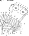
- Figure 9 shows a conventional multicylinder in-line internal combustion engine having a plurality of cylinders tilted at their upper portions toward the front side of the engine.
- an engine block 01 is formed by integrating a cylinder block and an upper crankcase 02.
- a crankcase is parted into the upper crankcase 02 of the engine block 01 and a lower crankcase 03 along a plane 04.
- a crankshaft 05 is rotatably supported in the plane 04, and a main shaft and a counter shaft (both not shown) for supporting gears of a transmission are also rotatably supported in the plane 04.
- a chain storing chamber 07 for driving overhead valve operating camshafts 06 is defined between the cylinders adjacent to each other rather than at one of right and left sides of the engine block 01.
- a supporting hole 09 for supporting a tensioner lifter 08 is formed through a wall of the chain storing chamber 07 at an upper side portion thereof so as to be inclined toward a line connecting axial centers of the cylinders.
- the engine block 01 is cast by using a mold as shown in Figure 9. That is, the mold shown is composed of an upper inner mold 010, a lower inner mold 011, a front outer mold 012, and a rear outer mold 013.
- a wall thickness of the engine block 01 at a portion thereof near the supporting hole 09 for the tensioner lifter 08 is made large, so as to reliably bear against vibration of a tensioner. Additionally, a padding of the engine block is increased in relation to mold releasing, and blowholes are easily generated. Furthermore, the amount of cutting of the wall of the supporting hole 09 is increased to result in an increase in cutting time and material cost. Accordingly, it is difficult to improve the productivity.
- a conventional four-cycle internal combustion engine is provided with a cam chain tensioner device for removing slack of an endless chain wound around cam sprockets integral with valve operating cams and a sprocket integral with a crankshaft to provide the endless chain with a proper tension.
- Japanese Utility Model Laid Open No. 56-47232 discloses a cam chain tensioner device such that an elastic member is provided under a pin for supporting a lower end of a tensioner body to thereby absorb vibration applied to the tension body due to the fluctuation in the tension of the cam chain.
- the vibration along a longitudinal direction of the tensioner body can be absorbed, but the vibration along the width of the cam chain cannot be absorbed.
- the present invention relates to an improvement in a mold for casting a laterally central portion of an engine block, which has solved the above problem.
- a mold for casting a laterally central portion of an engine block of a multicylinder in-line internal combustion engine having a plurality of cylinders tilted in a longitudinal direction perpendicular to a line of arrangement of the cylinders, a hollow chamber defined between the cylinders adjacent to each other and extending in an axial direction of the cylinders, a hole formed through a wall of the hollow chamber at an upper side portion thereof so as to be inclined downward toward a line connecting axial centers of the cylinders, a crankshaft extending horizontally in a lateral direction parallel to the line of arrangement of the cylinders, and a crankcase parted into an upper crankcase and a lower crankcase along a plane in which a center line of the crankshaft lies, the crankshaft being rotatably supported in the plane between the upper crankcase and the lower crankcase, the upper
- the thickness of the wall of the engine block cast by using the mold according to the present invention can be made as small as possible to thereby suppress the generation of blowholes and reduce the amount of a molten metal to be poured into the mold, thereby reducing a material cost. Furthermore, a cutting time for formation of the hole can be reduced to thereby greatly improve the productivity.
- the present invention further relates to an improvement in a cam chain tensioner device in an internal combustion engine, which has solved the problem of vibration along the width of the cam chain.
- a cam chain tensioner device in an internal combustion engine having a tensioner body formed with a mounting base portion projecting in a lateral direction of the tensioner body, the mounting base portion being mounted in mounting grooves formed on abutting surfaces of upper and lower crankcases of the internal combustion engine and being held between the upper and lower crankcases, the mounting grooves extending in a direction perpendicular to a chain storing portion; the improvement wherein the tensioner body has an elastic member integral therewith, the elastic member being located between opposite side surfaces of the tensioner body and opposite inner wall surfaces of the chain storing portion.
- the vibrational force in the lateral direction of the articulated cam chain that is prone to vibrate laterally responsive to pulsation of the internal combustion engine can be effectively damped to permit a valve operating mechanism to be operated silently and properly.
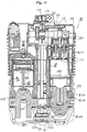
- crankshaft 6 is rotatably supported through sliding bearings (not shown) between a lower crankcase 2 and an engine block 3 as an integrated upper crankcase and cylinder block.
- a crankcase of the engine 1 is parted into the lower crankcase 2 and the upper crankcase.
- a cylinder head 4 is mounted on an upper end of the engine block 3, and a head cover 5 is mounted on an upper end of the cylinder head 4.
- the lower crankcase 2, the engine block 3, the cylinder head 4, and the head cover 5 are integrally connected together.
- the lower crankcase 2, the engine block 3, and the cylinder head 4 are formed by die casting of aluminum or aluminum alloy.
- crankshaft 6 is connected through connecting rods (not shown) to pistons (not shown) vertically reciprocatably fitted in cylinders 7 (see Fig. 3) of the engine block 3, so that the crankshaft 6 is rotationally driven by vertical movement of the pistons.
- the cylinder head 4 is provided with intake valves and exhaust valves (both not shown).
- Valve operating cams (not shown) are located over the intake valves and the exhaust valves on the extensions thereof.
- Camshafts 9 integral with the valve operating cams are rotatably supported between the cylinder head 4 and a cam holder (not shown).
- a cam chain storing chamber 10 for storing an endless chain 13 to be hereinafter described is defined at a laterally central portion between the right and left cylinders 7 in the engine block 3.
- a drive sprocket 11 is integrally formed on the crankshaft 6 at a central portion thereof, and cam sprockets 12 each having teeth twice in number that of the drive sprocket 11 is integrally mounted on the camshafts 9 at their central portions.
- the endless chain 13 is wound around the drive sprocket 11 and the cam sprockets 12 in the cam chain storing chamber 10. Accordingly, two revolutions of the crankshaft 6 bring about one revolution of the cam sprockets 12 and the valve operating cams.
- a chain guide 14 is provided in the cam chain storing chamber 10 on the front side of a vehicular body (i.e., on the left side as viewed in Figure 1 where exhaust ports are provided).
- a cam chain tensioner device 15 is provided in the cam chain storing chamber 10 on the rear side of the vehicular body (i.e., on the right side as viewed in Figure 1 where intake ports are provided), and a chain guide 16 is provided also on the upper side of the cam sprockets 12.
- the hollow cam chain storing chamber 10 comprises a cooling water passage.
- the cam chain tensioner device 15 includes a tensioner body 17 formed with a mounting base portion 18.
- a pivot pin 19 is integrally fitted with the mounting base portion 18 of the tensioner body 17.
- the pivot pin 19 is pivotally supported between the lower crankcase 2 and the engine block 3.
- a tensioner lifter 20 is provided on the rear side of the tensioner body 17 at a position somewhat higher than the center of the tensioner body 17.
- the tensioner lifter 20 has a rod 21 engaging at its tip with a recess 17a formed on a rear surface of the tensioner body 17.
- the tensioner lifter 20 is supported in a tensioner lifter supporting hole 22 formed through a rear wall of the engine block 3.
- the hole 22 comprises a cooling water communicating hole.
- the rod 21 of the tensioner lifter 20 is driven by a spring, hydraulic pressure, etc. to forward push the tensioner body 17 regardless of pivotal movement of the tensioner body 17, thereby maintaining a substantially constant tensile condition to the endless chain 13.
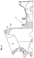
- a mold for casting the engine block 3 is composed of a lower or front outer mold 23 for defining the shape of a front lower inclined surface of the engine block 3, a upper or rear outer mold 24 for defining the shape of a rear upper inclined surface of the engine block 3 on the side where the cam chain tensioner device 15 is provided, a left outer mold 25 for defining the shape of a left surface of the engine block 3 (see Figure 4 showing a front elevation of the engine block 3, so that the left outer mold 25 is shown on the right-hand side as viewed in Figure 4), a right outer mold 26 for defining the shape of a right surface of the engine block 3 (see Figure 4), an upper inner mold 27 for defining the shape of an upper surface of the engine block 3 and retaining cylinder liners 8, and a lower inner mold 28 for defining the shape of a lower surface of the engine block 3.
- the upper inner mold 27 has right and left liner retaining projections 29 projecting downward so as to retain the cylinder liners 8 in the right and left cylinders 7 and close the bottom surfaces of the cylinder liners 8.
- the upper inner mold 27 is integrally formed with a cam chain storing chamber upper inner mold 30 disposed intermediate of the right and left liner retaining projections 29, for defining an upper portion of an inner surface of the tensioner lifter supporting hole 22.
- the lower inner mold 28 is formed with a cam chain storing chamber lower inner mold 31 opposed to the cam chain storing chamber upper inner mold 30 of the upper inner mold 27, for defining a lower portion of the inner surface of the tensioner lifter supporting hole 22.
- the lower inner mold 28 is further formed with an upper projection 32 projecting upward from an inner opening edge upper portion 22a of the tensioner lifter supporting hole 22 facing the cam chain storing chamber 10.
- the upper or rear outer mold 24 is formed with a lower projection 33 projecting downward from an outer opening edge lower portion 22b of the tensioner lifter supporting hole 22 facing the cam chain storing chamber 10.
- the cam chain storing chamber upper inner mold 30 of the upper inner mold 27 and the cam chain storing chamber lower inner mold 31 of the lower inner mold 28 are so formed as to contact together through a bent parting surface 34 inclined upward toward the rear side gradually at a front portion and steeply at a rear portion.
- the lower or front outer mold 23, the upper or rear outer mold 24, the left outer mold 25, the right outer mold 26, the upper inner mold 27, and the lower inner mold 28 are jointed together at their mating faces, and such a joined mold is set in a die casting apparatus (not shown). Then, the die casting apparatus is operated to pour a molten metal into the mold under pressure, thus obtaining a die casting.
- the cam chain storing chamber 10 is formed without the need of any machining.
- a wall thickness t of a portion for defining the tensioner lifter supporting hole 22 facing the cam chain storing chamber 10 is made smaller than a wall thickness T of a thick-walled peripheral wall of the tensioner lifter supporting hole 22 by the upper projection 32 and the lower projection 33.
- the wall thickness T of the peripheral wall of the tensioner lifter supporting hole 22 is set to a thickness enough to bear against an external force due to vibration or the like applied to the cam chain tensioner device 15. Accordingly, the amount of the molten metal to be required can be minimized to thereby reduce a material cost.
- the amount of cutting of the wall of the tensioner lifter supporting hole 22 can be greatly reduced with the result that a working time can be greatly reduced to thereby greatly improve the productivity.
- a recess 35 may be formed on the cam chain storing chamber upper inner mold 30 at a position adjacent to an upper portion 34a of the bent parting surface 34 and facing the cam chain storing chamber 10.
- bent parting surface 34 may be modified as shown by a broken line in Figure 8 to change the position of the recess 35.
- crankshaft 107 is rotatably supported through sliding bearings 106, see Fig. 11, between a lower crankcase 102 and an engine block 103 as an integrated upper crankcase and cylinder block.
- a crankcase of the engine 101 is parted into the lower crankcase 102 and the upper crankcase.
- a cylinder head 104 is mounted on an upper end of the engine block 103, and a head cover 105 is mounted on an upper end of the cylinder head 104.
- the lower crankcase 102, the engine block 103, the cylinder head 104, and the head cover 105 are integrally connected together.
- crankshaft 107 is connected through connecting rods 110 to pistons 109 vertically reciprocatably fitted in cylinders 108 of the engine block 103, so that the crankshaft 107 is rotationally driven by vertical movement of the pistons 109.
- the cylinder head 104 is provided with intake valves 111 and exhaust valves (not shown).
- Valve operating cams 112 are located over the intake valves 111 and the exhaust valves on the extensions thereof.
- Camshafts 113 integral with the valve operating cams 112 are rotatably supported between the cylinder head 104 and a cam holder 132.
- a sprocket 114 is integrally formed on the crankshaft 107 at a central portion thereof, and cam sprockets 115 each having teeth twice in number that of the sprocket 114 is integrally mounted on the camshafts 113 at their central portions.
- An endless chain 116 is wound around the sprocket 114 and the cam sprockets 115. Accordingly, two revolutions of the crankshaft 107 bring about one revolution of the cam sprockets 115 and the valve operating cams 112.
- a cam chain storing chamber 117 is defined in the engine block 103 and the cylinder head 104 at a position between the right and left cylinders 108.
- a chain guide 118 is provided in the cam chain storing chamber 117 on the front side of a vehicular body (i.e., on the side of exhaust ports).
- a cam chain tensioner device 120 is provided in the cam chain storing chamber 117 on the rear side of the vehicular body (i.e., on the side of intake ports), and a chain guide 119 is provided also on the upper side of the cam sprockets 115.
- the cam chain tensioner device 120 includes a tensioner body 123 consisting of a steel strip 121 and a rubber cushion 122 integrally bonded to a front surface and a lower end portion of the steel strip 121.
- a steel pivot, pin 125 is integrally fitted with a mounting base portion 124 of the tensioner body 123.
- a guide member 126 formed of a Teflon resin is integrally laminated on a front surface of the rubber cushion 122 which the endless chain 116 is in contact with.
- An upper half portion 126a of the guide member 126 is formed with a groove.
- a lifter 128 is provided on the rear side of the tensioner body 123 at a position somewhat higher than the center of the tensioner body 123.
- the lifter 128 has a rod 129 engaging at its tip with a recess 127 formed on a rear surface of the tensioner body 123.
- the recess 127 has a width substantially equal to the diameter of the rod 129.
- the rod 129 of the lifter 128 is driven by a spring, hydraulic pressure, etc. to forward push the tensioner body 123 regardless of pivotal movement of the tensioner body 123, thereby maintaining a substantially constant tensile condition to the endless chain 116.
- the pivot pin 125 integral with the tensioner body 123 is pivotally engaged at its opposite ends with recesses 130 formed on the engine block 103, and is held between the recesses 130 and the lower crankcase 102.
- a base portion 122a of the rubber cushion 122 at the mounting base portion 124 of the tensioner body 123 is held between right and left inner wall surfaces 117a of the cam chain storing chamber 117.
- the endless chain 116 is fitted in the groove 126a of the guide member 126 of the tensioner body 123. Further, the tip of the rod 129 of the lifter 128 is fitted in the recess 127 of the tensioner body 123, and both ends of the base portion 122a of the rubber cushion 122 at the mounting base portion 124 of the tensioner body 123 are held by the right and left inner wall surfaces 117a of the cam chain storing chamber 117, thereby elastically restrict lateral movement of the tensioner body 123.
Landscapes
- Engineering & Computer Science (AREA)
- Mechanical Engineering (AREA)
- Molds, Cores, And Manufacturing Methods Thereof (AREA)
- Valve-Gear Or Valve Arrangements (AREA)
- Cylinder Crankcases Of Internal Combustion Engines (AREA)
Applications Claiming Priority (2)
| Application Number | Priority Date | Filing Date | Title |
|---|---|---|---|
| JP23740393A JP3226680B2 (ja) | 1993-08-30 | 1993-08-30 | エンジンブロック巾方向中央部鋳型 |
| JP237403/93 | 1993-08-30 |
Publications (2)
| Publication Number | Publication Date |
|---|---|
| EP0657234A1 true EP0657234A1 (fr) | 1995-06-14 |
| EP0657234B1 EP0657234B1 (fr) | 1998-12-02 |
Family
ID=17014879
Family Applications (1)
| Application Number | Title | Priority Date | Filing Date |
|---|---|---|---|
| EP19940113530 Expired - Lifetime EP0657234B1 (fr) | 1993-08-30 | 1994-08-30 | Moule pour la coulée de la partie centrale latérale d'un bloc-moteur |
Country Status (4)
| Country | Link |
|---|---|
| EP (1) | EP0657234B1 (fr) |
| JP (1) | JP3226680B2 (fr) |
| DE (1) | DE69414986T2 (fr) |
| ES (1) | ES2125385T3 (fr) |
Cited By (1)
| Publication number | Priority date | Publication date | Assignee | Title |
|---|---|---|---|---|
| US7814879B2 (en) | 2008-04-23 | 2010-10-19 | Techtronic Outdoor Products Technology Limited | Monolithic block and valve train for a four-stroke engine |
Families Citing this family (2)
| Publication number | Priority date | Publication date | Assignee | Title |
|---|---|---|---|---|
| US7405582B2 (en) | 2006-06-01 | 2008-07-29 | Advantest Corporation | Measurement board for electronic device test apparatus |
| CN105964914B (zh) * | 2016-07-25 | 2017-11-24 | 大连金河铸造有限公司 | 柴油机缸体凸轮室防渗漏铸造工艺 |
Citations (3)
| Publication number | Priority date | Publication date | Assignee | Title |
|---|---|---|---|---|
| DE84304C (fr) * | ||||
| DD109333A1 (fr) * | 1974-01-15 | 1974-11-05 | ||
| US4757857A (en) * | 1985-12-18 | 1988-07-19 | Fritz Winter Eisengiesserei O.H.G. | Mold for casting cylinder blocks of combustion engines |
-
1993
- 1993-08-30 JP JP23740393A patent/JP3226680B2/ja not_active Expired - Fee Related
-
1994
- 1994-08-30 DE DE1994614986 patent/DE69414986T2/de not_active Expired - Fee Related
- 1994-08-30 EP EP19940113530 patent/EP0657234B1/fr not_active Expired - Lifetime
- 1994-08-30 ES ES94113530T patent/ES2125385T3/es not_active Expired - Lifetime
Patent Citations (3)
| Publication number | Priority date | Publication date | Assignee | Title |
|---|---|---|---|---|
| DE84304C (fr) * | ||||
| DD109333A1 (fr) * | 1974-01-15 | 1974-11-05 | ||
| US4757857A (en) * | 1985-12-18 | 1988-07-19 | Fritz Winter Eisengiesserei O.H.G. | Mold for casting cylinder blocks of combustion engines |
Non-Patent Citations (1)
| Title |
|---|
| DATABASE WPI Week 7507, Derwent World Patents Index; AN 75-10928W 07! * |
Cited By (1)
| Publication number | Priority date | Publication date | Assignee | Title |
|---|---|---|---|---|
| US7814879B2 (en) | 2008-04-23 | 2010-10-19 | Techtronic Outdoor Products Technology Limited | Monolithic block and valve train for a four-stroke engine |
Also Published As
| Publication number | Publication date |
|---|---|
| DE69414986T2 (de) | 1999-04-22 |
| EP0657234B1 (fr) | 1998-12-02 |
| JP3226680B2 (ja) | 2001-11-05 |
| JPH0760404A (ja) | 1995-03-07 |
| DE69414986D1 (de) | 1999-01-14 |
| ES2125385T3 (es) | 1999-03-01 |
Similar Documents
| Publication | Publication Date | Title |
|---|---|---|
| JPS6352201B2 (fr) | ||
| JPS6036704A (ja) | 往復ピストン・内燃機関のチエーン駆動装置 | |
| JP2530930Y2 (ja) | 駆動伝達装置 | |
| JP4197067B2 (ja) | 車両用エンジンの動力伝達装置 | |
| JP4361772B2 (ja) | 4サイクルエンジンの動弁装置 | |
| EP0657234A1 (fr) | Moule pour la coulée de la partie centrale latérale d'un bloc-moteur | |
| JPH0211830A (ja) | 4サイクルエンジンのカムチェーンテンショナ | |
| JP3166532B2 (ja) | 内燃機関のチェーンケース構造 | |
| JP3111845B2 (ja) | 内燃機関のチェーンケース構造 | |
| JP2018054061A (ja) | 内燃機関 | |
| JPH086564B2 (ja) | V型dohc機関のカム軸駆動装置 | |
| JP3157365B2 (ja) | 内燃機関におけるカムチェーンテンショナ装置 | |
| JP7363350B2 (ja) | エンジンの補機取付構造 | |
| JP4603206B2 (ja) | V型エンジン | |
| JP2741078B2 (ja) | V型水冷エンジンのカム軸駆動装置 | |
| JP2000136863A (ja) | カムチェーンガイドの取付構造 | |
| JPS6345566Y2 (fr) | ||
| JP4544100B2 (ja) | エンジンの前部構造 | |
| JPH10281244A (ja) | エンジンのタイミングチェーン案内部材の支持構造 | |
| JP3862462B2 (ja) | カムフォロア脱落防止構造 | |
| JP3795429B2 (ja) | 船外機用バーチカルエンジン | |
| JPH0732884Y2 (ja) | V型エンジンの潤滑油通路 | |
| JPH11182325A (ja) | 複数気筒エンジンのシリンダブロック | |
| JP2010019191A (ja) | エンジン | |
| JP2546615Y2 (ja) | Dohcエンジンのカム潤滑装置 |
Legal Events
| Date | Code | Title | Description |
|---|---|---|---|
| PUAI | Public reference made under article 153(3) epc to a published international application that has entered the european phase |
Free format text: ORIGINAL CODE: 0009012 |
|
| 17P | Request for examination filed |
Effective date: 19941220 |
|
| AK | Designated contracting states |
Kind code of ref document: A1 Designated state(s): DE ES FR GB |
|
| 17Q | First examination report despatched |
Effective date: 19970618 |
|
| GRAG | Despatch of communication of intention to grant |
Free format text: ORIGINAL CODE: EPIDOS AGRA |
|
| GRAG | Despatch of communication of intention to grant |
Free format text: ORIGINAL CODE: EPIDOS AGRA |
|
| GRAH | Despatch of communication of intention to grant a patent |
Free format text: ORIGINAL CODE: EPIDOS IGRA |
|
| GRAH | Despatch of communication of intention to grant a patent |
Free format text: ORIGINAL CODE: EPIDOS IGRA |
|
| GRAA | (expected) grant |
Free format text: ORIGINAL CODE: 0009210 |
|
| AK | Designated contracting states |
Kind code of ref document: B1 Designated state(s): DE ES FR GB |
|
| REF | Corresponds to: |
Ref document number: 69414986 Country of ref document: DE Date of ref document: 19990114 |
|
| REG | Reference to a national code |
Ref country code: ES Ref legal event code: FG2A Ref document number: 2125385 Country of ref document: ES Kind code of ref document: T3 |
|
| ET | Fr: translation filed | ||
| PLBE | No opposition filed within time limit |
Free format text: ORIGINAL CODE: 0009261 |
|
| STAA | Information on the status of an ep patent application or granted ep patent |
Free format text: STATUS: NO OPPOSITION FILED WITHIN TIME LIMIT |
|
| 26N | No opposition filed | ||
| REG | Reference to a national code |
Ref country code: GB Ref legal event code: IF02 |
|
| PGFP | Annual fee paid to national office [announced via postgrant information from national office to epo] |
Ref country code: FR Payment date: 20050809 Year of fee payment: 12 |
|
| PGFP | Annual fee paid to national office [announced via postgrant information from national office to epo] |
Ref country code: DE Payment date: 20050825 Year of fee payment: 12 |
|
| PG25 | Lapsed in a contracting state [announced via postgrant information from national office to epo] |
Ref country code: DE Free format text: LAPSE BECAUSE OF NON-PAYMENT OF DUE FEES Effective date: 20070301 |
|
| REG | Reference to a national code |
Ref country code: FR Ref legal event code: ST Effective date: 20070430 |
|
| PGFP | Annual fee paid to national office [announced via postgrant information from national office to epo] |
Ref country code: ES Payment date: 20070926 Year of fee payment: 14 |
|
| PGFP | Annual fee paid to national office [announced via postgrant information from national office to epo] |
Ref country code: GB Payment date: 20070829 Year of fee payment: 14 |
|
| PG25 | Lapsed in a contracting state [announced via postgrant information from national office to epo] |
Ref country code: FR Free format text: LAPSE BECAUSE OF NON-PAYMENT OF DUE FEES Effective date: 20060831 |
|
| GBPC | Gb: european patent ceased through non-payment of renewal fee |
Effective date: 20080830 |
|
| REG | Reference to a national code |
Ref country code: ES Ref legal event code: FD2A Effective date: 20080901 |
|
| PG25 | Lapsed in a contracting state [announced via postgrant information from national office to epo] |
Ref country code: GB Free format text: LAPSE BECAUSE OF NON-PAYMENT OF DUE FEES Effective date: 20080830 |
|
| PG25 | Lapsed in a contracting state [announced via postgrant information from national office to epo] |
Ref country code: ES Free format text: LAPSE BECAUSE OF NON-PAYMENT OF DUE FEES Effective date: 20080901 |