EP0657294B1 - Automatische Druckspalteinstelleinrichtung für einen Drucker - Google Patents
Automatische Druckspalteinstelleinrichtung für einen Drucker Download PDFInfo
- Publication number
- EP0657294B1 EP0657294B1 EP94119538A EP94119538A EP0657294B1 EP 0657294 B1 EP0657294 B1 EP 0657294B1 EP 94119538 A EP94119538 A EP 94119538A EP 94119538 A EP94119538 A EP 94119538A EP 0657294 B1 EP0657294 B1 EP 0657294B1
- Authority
- EP
- European Patent Office
- Prior art keywords
- carriage
- platen
- recording sheet
- load
- contact
- Prior art date
- Legal status (The legal status is an assumption and is not a legal conclusion. Google has not performed a legal analysis and makes no representation as to the accuracy of the status listed.)
- Expired - Lifetime
Links
- 238000001514 detection method Methods 0.000 claims description 22
- 238000000034 method Methods 0.000 claims description 3
- 230000000694 effects Effects 0.000 description 8
- 238000010586 diagram Methods 0.000 description 5
- 230000010354 integration Effects 0.000 description 3
- 238000010186 staining Methods 0.000 description 2
- 230000005540 biological transmission Effects 0.000 description 1
- 238000010276 construction Methods 0.000 description 1
- 230000007423 decrease Effects 0.000 description 1
- 230000003247 decreasing effect Effects 0.000 description 1
- 230000002950 deficient Effects 0.000 description 1
- 230000001419 dependent effect Effects 0.000 description 1
- 230000005284 excitation Effects 0.000 description 1
- 238000007689 inspection Methods 0.000 description 1
Images


Classifications
-
- B—PERFORMING OPERATIONS; TRANSPORTING
- B41—PRINTING; LINING MACHINES; TYPEWRITERS; STAMPS
- B41J—TYPEWRITERS; SELECTIVE PRINTING MECHANISMS, i.e. MECHANISMS PRINTING OTHERWISE THAN FROM A FORME; CORRECTION OF TYPOGRAPHICAL ERRORS
- B41J25/00—Actions or mechanisms not otherwise provided for
- B41J25/304—Bodily-movable mechanisms for print heads or carriages movable towards or from paper surface
- B41J25/308—Bodily-movable mechanisms for print heads or carriages movable towards or from paper surface with print gap adjustment mechanisms
- B41J25/3082—Bodily-movable mechanisms for print heads or carriages movable towards or from paper surface with print gap adjustment mechanisms with print gap adjustment means on the print head carriage, e.g. for rotation around a guide bar or using a rotatable eccentric bearing
-
- B—PERFORMING OPERATIONS; TRANSPORTING
- B41—PRINTING; LINING MACHINES; TYPEWRITERS; STAMPS
- B41J—TYPEWRITERS; SELECTIVE PRINTING MECHANISMS, i.e. MECHANISMS PRINTING OTHERWISE THAN FROM A FORME; CORRECTION OF TYPOGRAPHICAL ERRORS
- B41J25/00—Actions or mechanisms not otherwise provided for
- B41J25/304—Bodily-movable mechanisms for print heads or carriages movable towards or from paper surface
- B41J25/308—Bodily-movable mechanisms for print heads or carriages movable towards or from paper surface with print gap adjustment mechanisms
Definitions
- This invention relates to devices for automatically adjusting a gap between a platen and a recording head in accordance with the thickness of a recording sheet.
- Prior art document EP-A-0393759 discloses an automatic platen gap adjusting device for a printer, comprising carriage driving means for driving a carriage in parallel with a platen shaft, the carriage carrying a recording head means for detecting a load of the carriage driving means when the carriage is moved in parallel with the platen shaft at a predetermined speed, and contact judgement means for judging whether or not the recording head is in contact with the recording sheet based on a comparison between a load at the time the recording sheet is inserted in the printer and another value. Further, moving means are provided for moving the carriage in a direction orthogonal to the platen shaft based on the judgement of the contact judgement means.
- a wire impinging speed In a recording head, and particularly a wire dot type recording head that prints data by impinging wires onto a recording sheet through an ink ribbon, a wire impinging speed must be minimized in order to achieve high speed printing.
- the recording head Since the wire dot type recording head is mechanically rigid and capable of copying data through a copying material, the recording head can be used with a wide variety of different types of sheets. This feature is problematic, however, because the distance between the recording head and the recording sheet varies by a greater degree than in printers of other types.
- a printer especially a wire dot type printer usually has a mechanism for adjusting a relative gap length between the platen and the recording head.
- the user must be well skilled in selecting the optimal gap for each kind of sheet used, and the selecting operation is cumbersome.
- the printer disclosed in Japanese Examined Patent Publication No. 4-14634 is intended to overcome the above noted problems.
- This printer has an encoder that generates pulse signals in association with the movement of the carriage from an initial position thereof, and a control section that processes a feedback pulse signal from the encoder.
- the first instance of a carriage driving pulse motor losing synchronism is detected from a change in the number of pulses from the encoder due to an abutment of the recording head against a recording sheet, and the thickness of the recording sheet is calculated based on the amount of movement of the carriage up to the moment of abutment, so that the position of the carriage can be controlled based on the recording sheet thickness data.
- the invention has been made in consideration of the aforementioned problems, and the object of the invention is, therefore, to provide an automatic platen gap adjusting device capable of preventing the recording head from being broken or stained.
- the invention is directed to devices for adjusting the gap to an optimal value by judging the thickness of a loaded recording sheet.
- This invention achieves the above object by not only measuring the thickness of a recording sheet by causing the carriage to come in pressure contact with the recording sheet with a sufficiently small force, but also by automatically judging the gap between the recording head and the recording sheet.
- an automatic platen gap adjusting device for a printer includes: a carriage motor for driving a carriage in parallel with a platen shaft, the carriage carrying a recording head; a means for detecting a load from a load current of the carriage motor when the carriage is moved in parallel with the platen shaft at a predetermined speed; an initial load storage means for storing the load at the time a recording sheet is not loaded as an initial load; a contact judgment means for comparing the load at the time the recording sheet is loaded with the initial load and judging that the recording head is in contact with the recording sheet when a difference between both loads exceeds a reference value; means for moving the carriage in direction which contains at least a component orthogonal to the platen shaft whereby said means are preferably provided by a stepper motor; a movement amount detection means for generating a number of pulse signals proportional to an amount of movement of the carriage in the direction orthogonal to the platen shaft; an abutment judgment means for moving the carriage toward a platen from a reference position,
- the platen gap adjusting device advantageously may further comprise a sheet thickness calculation means for calculating a thickness of a recording sheet based on the amount of movement of the carriage from the reference position upon output of a signal from the abutment judgment means, and optionally a control means for adjusting a relative gap length between the carriage and the platen by driving the moving means (e.g., the stepper motor) based on data from the sheet thickness calculation means.
- a sheet thickness calculation means for calculating a thickness of a recording sheet based on the amount of movement of the carriage from the reference position upon output of a signal from the abutment judgment means
- a control means for adjusting a relative gap length between the carriage and the platen by driving the moving means (e.g., the stepper motor) based on data from the sheet thickness calculation means.
- a time difference between the moving means (e.g., the stepper motor) drive pulse and the pulse signal from the movement detection means is detected.
- the integrated value of the time differences has reached a preset value and at a stage before losing synchronism, abutment of the recording head against the recording sheet is judged, and the thickness of the recording sheet is determined or calculated from the amount of movement of the carriage up to the moment of abutment.
- the relative gap length between the platen and the carriage is set to an optimal value.
- a load applied to the carriage motor and a load with no recording sheet loaded can be compared with each other by moving the carriage in the main scanning direction after the platen gap has been adjusted in order to check that the recording head is not in contact with the recording sheet.
- Figures 1(A) and 1(B) are different views of an embodiment of a mechanism for adjusting a relative gap length between the platen and the recording head of a serial printer to which the invention can be applied.
- reference numeral 1 denotes a carriage having an impact wire type recording head 2 carried thereon and being disposed on a guide shaft 3 and a fixed guide shaft 4.
- the guide shaft 3 is mounted on a base so as to be eccentrically rotatable.
- the carriage 1 can move in directions indicated by the double ended arrow "A" in Figure 1 (A).
- a relative gap length "G" of the recording head 2 with respect to the platen 5 can be adjusted by the amount of rotation of the guide shaft 3.
- the carriage 1 is connected to a carriage motor 6, e.g., a dc motor, through a timing belt 9, so that the carriage 1 can shuttle in directions of the platen shaft indicated by the double ended arrow "B" in Figure 1(B) with the gap length "G" adjusted by the guide shaft 3.
- a carriage motor 6 e.g., a dc motor
- Reference numeral 10 denotes a stepper motor that rotates the guide shaft 3.
- This stepper motor 10 drives the guide shaft 3 by 2-2 phase excitation and at a cycle of 3.5 ms, and is connected to a driven wheel 12 of the guide shaft 3 through a reduction gear 11.
- a shaft 13 of the stepper motor 10 carries a code disk 15 of a first encoder 14 that generates a pulse signal indicating a value proportional to the angle of rotation thereof.
- the code pattern of the code disk 15 is such that a single pulse width signal can be generated from a code detector 16 in synchronism with single phase drive of the stepper motor 10.
- Reference numeral 18 denotes a position detection means that is positioned so as to output a signal when the carriage 1 has reached a reference position at which the carriage 1 is farthest from the platen 5.
- a microswitch may be used as the position detection means in one preferred embodiment.
- a second encoder 25 is provided to measure movement of the carriage 1 in the main scanning direction.
- the second encoder 25 comprises a code disk 22 fixed on an idler 20 of the timing belt 9 and a code detector 24 that detects a code indicated by the code disk.
- Reference numeral 26 denotes a controller, which receives signals from the first and second encoders 14, 25 as well as from the position detector 18, and controls the carriage motor 6 and the stepper motor 10.
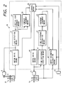
- FIG. 2 shows an embodiment of the controller 26.
- reference numeral 30 denotes a motor drive means for driving the motor 6 that moves the carriage 1 in the main scanning direction.
- the motor drive means 30 is activated by a signal from a control means 46, which judges the carriage 1 moving speed from a signal from the second encoder 25, and adjusts the duty of a current pulse to be supplied to the carriage motor 6 so that the carriage 1 moving speed becomes constant.
- Reference numeral 31 denotes a load detection means, which detects a load applied to the carriage motor 6 based on the duty of the current pulse supplied to the carriage motor 6, and delivers the detected value to an initial load storage means 32 when no recording sheet is loaded.
- Reference numeral 33 denotes a contact judgment means, which calculates a difference between a signal from the load detection means 31 when the recording sheet is loaded and the value of the initial load storage means 32, compares the difference with a reference value, and judges whether the recording head 2 is in contact with the recording sheet when the difference exceeds the reference value.
- Reference numeral 40 denotes a motor drive means, which drives the stepper motor 10 to move the carriage 1 in the direction orthogonal to the platen 5.
- Reference numeral 41 denotes a time difference detection means, which judges whether a time difference between the cycle of a pulse signal from the first encoder 14 and the cycle of a drive signal of the stepper motor 10 changes, and outputs an amount of change ⁇ Tn in the time difference when the time difference has changed.
- Reference numeral 42 denotes a time difference integration means, which calculates an integrated value ⁇ ( ⁇ Tn) of the amounts of change ⁇ Tn in the time difference, and outputs the integrated value ⁇ to an abutment judgment means 43, which will be described below.
- Reference numeral 43 denotes the abutment judgment means, which outputs a signal upon coincidence of the integrated value of the amounts of change in the time difference from the time difference integration means 43 with a reference value.
- the reference value in this embodiment is a value half or less of the cycle of the drive pulse of the stepper motor 10, e.g., 1.5 ms.
- Reference numeral 44 denotes a sheet thickness calculation means, which counts the number of pulse signals from the encoder 14 based on a signal from the position detector 18, stops counting in accordance with a signal from the abutment judgment means 43, and calculates the thickness of a recording sheet based on the pulse signal count.
- Reference numeral 46 denotes the control means, which not only controls the stepper motor 10 for adjusting the platen gap, but also effects a sequence control for checking that the recording sheet is not in contact with the recording head 2 after the platen gap has been adjusted.
- the control means 46 drives the carriage motor 6 with no recording sheet being loaded, e.g., at the time a power switch is not turned on; sets the carriage 1 to the reference position thereof by causing the carriage 1 to retreat in such a direction as to move away from the platen 5 until a signal is outputted from the position detector 18 upon pressing of a loading switch (not shown); causes the carriage 1 to move toward the platen 5 to thereby cause the recording head 2 to be abutted against the recording sheet; drives the stepper motor 10 so that an optimal gap length is given to the loaded recording sheet after the thickness of the recording sheet has been detected; and finally drives the carriage motor 6 again after the platen gap has been adjusted.
- Step 1 When a power switch (not shown) of a printer has been turned on (Step 1), the control means 46 drives the carriage motor 6 to cause the carriage 1 to move along the platen 5 (Step 2).
- Step 3 the load detection means 31 detects a load of the carriage motor 6 from the duty of a current pulse supplied to the carriage motor 6, and stores in the initial load storage means 32 the detected load as a reference load of the carriage at the time the recording head 2 is not in contact with the recording sheet (Step 4).
- Step 5 When the loading switch is pressed to load the recording sheet (Step 5), the recording sheet is set on the platen 5 by a loading mechanism (not shown) (Step 6). Then, the control means 46 instructs the motor drive means 30 to move the carriage 1 to substantially the center of the print region (Step 7) and temporarily drives the stepper motor 5 reversely to cause the carriage 1 to retreat in such a direction as to be opposite to the platen 5, i.e., toward the position detector 18. When the carriage 1 has reached the reference position as a result of this control, a signal is generated from the position detector 18, which causes the control means 46 to stop the stepper motor 10 (Step 8).
- the control means 46 forwardly drives the stepper motor 10 at a predetermined rotational speed to move the carriage 1 toward the platen 5 and, at the same time, counts the number of pulse signals from the first encoder 14.
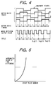
- the time difference detection means 41 judges whether a time difference is present between the drive pulse cycle of the stepper motor 10 and the pulse signal cycle of the rotary encoder 14. Since the load applied to the stepper motor 10 remains constant until the recording head 2 is abutted against the recording sheet, there is no time difference between the cycle of each pulse signal from the rotary encoder 14 and the drive pulse cycle of the stepper motor 10 during this period and, therefore, the integrated value thereof remains equal to zero ( Figure 4) (Step 9).
- the recording head 2 starts to abut against the recording sheet, which in turn decreases the rotational speed of the first encoder 14 because the load is applied to the carriage 1.
- the cycle of each pulse signal from the encoder 14 is increased to cause an amount of change ⁇ T to the time difference T with respect to the drive signal of the stepper motor 10.
- the time difference integration means 42 sequentially integrates such amounts of change ⁇ T in the time difference and delivers the integrated value to the abutment judgment means 43.
- the load of the stepper motor 10 increases with increasing distance of movement of the carriage 1 toward the platen 5 ( Figure 5), causing the integrated value ⁇ ( ⁇ T) of the amounts of change ⁇ Tn in the time difference to increase so drastically as to reach the preset value (Step 10). Accordingly, the abutment judgment means 43 judges that the recording head 2 has been abutted against the recording sheet and thereby generates a signal that indicates the abutment.
- the control means 46 stops the rotation of the stepper motor 10 upon reception of the signal from the abutment judgment means 43, whereas the sheet thickness calculation means 44 calculates the thickness of the recording sheet by stopping the counting of pulses from the first encoder 14 based on the signal from the abutment judgment means 43 (Step 11).
- the control means 46 causes the carriage 1 to retreat from the platen 5 and fixes the carriage 1 at an optimal position by driving the stepper motor 10 based on the calculated sheet thickness so that an optimal gap length can be given to the recording sheet (Step 12).
- the control means 46 causes the carriage 1 to move in parallel with the platen 5 by driving the carriage motor 6 again (Step 13).
- the load detection means 31 detects a load required for driving the carriage 1 based on the duty of a current pulse that drives the carriage motor 6 (Step 15).
- the contact judgment means 33 calculates a difference between a currently detected load and the load stored in the initial load storage means 32 (Step 16). If the calculated difference is smaller than the reference value (Step 16), then the printer, being ready to print, is set to a stand-by mode.
- the control means 46 recognizing that the carriage 1 has a high travel resistance due to the recording head 2 and the ink ribbon being in contact with the recording sheet, increases the platen gap by applying a drive pulse to the stepper motor 10 so that the carriage 1 makes a retreat equivalent to a predetermined distance, e.g., a single step, from the platen 5 (Step 18).
- the control means 46 drives the carriage motor 6 again to move the carriage 1 along the length of the shaft of the platen 5 (Step 19).
- Step 21 the load of the carriage motor 6 is detected (Step 21) and a difference between the detected load and the load in the initial load storage means 32 is calculated (Step 21). If the difference is smaller than the reference value (Step 22), the printer is set to the stand-by mode with the adjusted platen gap and waits for a print data input. On the other hand, if the load has not decreased in spite of the platen gap readjustment (Step 22), then the control means 46 ejects the recording sheet by judging the recording sheet loading as being erroneous (Step 23), and gives an alarm to the user for inspection as necessary.
- the reference position detection means 18 is arranged to set the reference position in the aforementioned embodiment, it is apparent that a similar effect can be obtained by measuring the distance between an arbitrary carriage position and the platen surface by the carriage to retreat to the original position, and then calculating the distance by which the carriage is abutted against the recording sheet after loading the recording sheet onto the platen.
- the invention may preferably include : a means for detecting a load from a load current of a carriage motor when a carriage is moved in parallel with a platen shaft at a predetermined speed; an initial load storage means for storing a load at the time a recording sheet is not loaded as an initial load; a contact judgment means for comparing a load at the time the recording sheet is loaded with the initial load, and judging that the recording head is in contact with the recording sheet when a difference between both loads exceeds a reference value; a stepper motor for moving the carriage in a direction orthogonal to the platen shaft; a movement amount detection means for generating a number of pulse signals proportional to an amount of movement of the carriage in the direction orthogonal to the platen shaft; an abutment judgment means for moving the carriage toward the platen from a reference position, integrating time differences between respective drive pulses of the stepper motor and corresponding pulse signals generated from the movement amount detection means as a result of the drive of the stepper motor by the drive
- the platen gap can be set to an optimal value by judging the time upon which the recording head has been abutted against the recording sheet without applying an unnecessarily large force to the recording sheet. Moreover, breakage and staining of the recording head due to defective loading of a recording sheet can be prevented by checking whether there is contact between the recording head and the recording sheet after the platen gap has been set.
Landscapes
- Common Mechanisms (AREA)
Claims (8)
- Automatische Walzenspalteinstelleinrichtung für einen Drucker mit:einem Schlittenantriebsmittel (6,9) zum Antrieb eines Schlittens (1) parallel zu einer Walzenwelle, wobei der Schlitten (1) einen Aufzeichnungskopf (2) trägt;einem Mittel (31) zum Erfassen einer Last des Schlittenantriebsmittels (6,9), wenn der Schlitten (1) parallel zur Walzenwelle mit einer vorbestimmten Geschwindigkeit bewegt wird;einem Kontaktprüfmittel (33) zur Prüfung, ob der Aufzeichnungskopf (2) in Kontakt mit dem Aufzeichnungsblatt steht oder nicht auf der Grundlage eines Vergleichs zwischen einer Last zum Zeitpunkt der Einführung des Aufzeichnungsblatts in den Drucker und einem anderen Wert; undeinem Bewegungsmittel (3,10,11,12) zum Bewegen des Schlittens (1) in eine Richtung orthogonal zu der Walzenwelle auf der Grundlage der Prüfung des Kontaktprüfmittels (33),
gekennzeichnet durchein Anfangslastspeichermittel (32) zum Speichern einer Anfangslast bevor ein Aufzeichnungsblatt in den Drucker eingeführt wird, wobei das Kontaktprüfmittel (33) prüft, ob der Aufzeichnungskopf (2) in Kontakt mit dem Aufzeichnungsblatt steht oder nicht auf der Basis eines Vergleichs zwischen einer Last zum Zeitpunkt der Einführung des Aufzeichnungsblattes in den Drucker und der Anfangslast. - Automatische Walzenspalteinstelleinrichtung gemäß Anspruch 1, bei derdas Schlittenantriebsmittel (6,9) einen Schlittenmotor (6) zum Antrieb des Schlittens (1) parallel zu der Walzenwelle aufweist;das Erfassungsmittel (31) eine momentan von dem Schlittenmotor (6) abgegebene Last erfaßt;das Kontaktprüfmittel (33) prüft, ob der Aufzeichnungskopf (2) in Kontakt mit dem Aufzeichnungsblatt steht oder nicht, wenn ein Unterschied zwischen diesen Lasten einen Bezugswert überschreitet;das Bewegungsmittel (3,10,11,12) einen Schrittmotor (10) umfaßt;ein Bewegungsgrößenerfassungsmittel (14,15) eine Anzahl an Impulssignalen proportional zu einer Bewegungsgröße des Schlittens (1) in der Richtung senkrecht zur Walzenwelle erzeugt;ein Abstandsprüfmittel (43) die Zeitunterschiede zwischen entsprechenden Antriebsimpulsen des Schrittmotors (10) und entsprechenden Impulssignalen, die von dem Bewegungsgrößenerfassungsmittel (14, 15) in Übereinstimmung mit dem Antrieb des Schrittmotors (10) durch die Antriebsimpulse erzeugt werden, integriert und prüft, ob der integrierte Wert der Zeitunterschiede einen vorgegebenen Wert erreicht hat oder nicht;ein Blattdickenberechnungsmittel (44) eine Dicke des Aufzeichnungsblattes berechnet auf der Basis der Bewegungsgröße des Schlittens (1) aufgrund einer Bezugsposition bei Abgabe eines Signals von dem Abstandsprüfmittel (43), das angibt, daß der integrierte Wert der Zeitunterschiede einen vorgegebenen Wert erreicht hat; undein Steuerungsmittel (46) eine relative Spaltenlänge zwischen dem Schlitten (1) und der Walze (5) durch Antrieb des Schrittmotors (10) auf der Basis von Daten des Blattdickenberechnungsmittels (44) einstellt.
- Automatische Walzenspalteinstelleinrichtung gemäß Anspruch 2, bei der das Steuerungsmittel (46) ein Mittel (40) aufweist, das den Schlitten (1) veranlaßt, sich von der Walze zurückzuziehen, indem der Schrittmotor (10) um einen vorgegebenen Betrag angetrieben wird, wenn ein Kontakt zwischen dem Aufzeichnungskopf (2) und dem Aufzeichnungsblatt von dem Kontaktprüfmittel (33) erfaßt wird.
- Automatische Walzenspalteinstelleinrichtung gemäß Anspruch 1, bei der:das Schlittenantriebsmittel (6,9) einen Schlittenmotor (6) zum Antrieb des Schlittens (1) parallel zu der Walzenwelle aufzeigt, wobei der Schlitten (1) den Aufzeichnungskopf (2) trägt;das Bewegungsmittel (3,10,11,12) einen Spalteinstellmotor (10) aufweist zur Einstellung einer relativen Spaltlänge zwischen dem Schlitten (1) und der Walze (5) durch Bewegen des Schlittens (1) in die Richtung orthogonal zu der Walzenwelle,das Kontaktprüfmittel (33) eine Last zum Zeitpunkt der Einführung des Aufzeichnungsblattes in den Drucker mit der Anfangslast vergleicht und prüft, ob der Aufzeichnungskopf in Kontakt mit dem Aufzeichnungsblatt steht, wenn ein Unterschied zwischen diesen Lasten einen Bezugswert überschreitet; unddas Steuerungsmittel (46) den Schlitten (1) dazu veranlaßt, sich von der Walze (5) zurückzuziehen, indem der Spalteinstellmotor (10) um einen vorgegebenen Betrag angetrieben wird, wenn ein Kontakt zwischen dem Aufzeichnungskopf (2) und dem Aufzeichnungsblatt von dem Kontaktprüfmittel (33) erfaßt wird.
- Automatische Walzenspalteinstelleinrichtung gemäß einem der Ansprüche 2 bis 4, bei der das Bewegungsgrößenerfassungsmittel (14,15) einen drehbaren Codierer (14) aufweist.
- Automatische Walzenspalteinstelleinrichtung gemäß einem der Ansprüche 2 bis 4, bei der das Bewegungsgrößenerfassungsmittel (14,15) einen linearen Codierer aufweist.
- Automatische Walzenspalteinstelleinrichtung gemäß Anspruch 1, bei derdas Schlittenantriebsmittel (6,9) einen Schlittenmotor (6) zum Antrieb des Schlittens (1) parallel zu der Walzenwelle aufweist;das Erfassungsmittel (31) eine momentan von dem Schlittenmotor (6) abgegebene Last erfaßt;das Kontaktprüfmittel (33) prüft, ob der Aufzeichnungskopf (2) in Kontakt mit dem Aufzeichnungsblatt steht oder nicht, wenn ein Unterschied zwischen diesen Lasten einen Bezugswert überschreitet;das Bewegungsmittel (3,10,11,12) einen Schrittmotor (10) umfaßt;das Bewegungsgrößenerfassungsmittel (14,15) eine Anzahl von Impulssignalen proportional zu einer Bewegungsgröße des Schlittens (1) in der Richtung orthogonal zu der Walzenwelle erzeugt;ein Abstandsprüfmittel (43) prüft, wenn der Schlitten (1) zum ersten Mal eines der Elemente ausgewählt aus der Walze (5) und/oder dem Aufzeichnungsblatt berührt, indem es ermittelt, ob eine Anzahl von Antriebsimpulsen des Schrittmotors innerhalb eines Zyklus der Pulssignale des Bewegungsgrößenerfassungsmittels (14,15) einen vorgegebenen Wert erreicht hat;ein Blattdickenberechnungsmittel (44) eine Dicke des Aufzeichnungsblattes berechnet auf der Basis der Bewegungsgröße des Schlittens (1) von einer Bezugsposition bei Ausgabe eines Signals von dem Abstandsprüfmittel (43), das angibt, daß der vorgegebene Wert erreicht worden ist; undein Steuerungsmittel (46) eine relative Spaltenlänge zwischen dem Schlitten (1) und der Walze (5) durch Antrieb des Schrittmotors (10) auf der Basis von Daten des Blattdickenberechnungsmittels (44) einstellt.
- Verfahren zur Einstellung eines Walzenspaltes in einem Drucker, bei demein einen Aufzeichnungskopf tragender Schlitten (1) parallel zu einer Walzenwelle angetrieben wird;eine Last erfaßt wird, wenn der Schlitten (1) parallel zu der Walzenwelle mit einer vorgegebenen Geschwindigkeit angetrieben wird;geprüft wird, ob der Aufzeichnungskopf in Kontakt mit dem Aufzeichnungsblatt steht oder nicht, indem eine Last zum Zeitpunkt des Einführens des Aufzeichnungsblattes in den Drucker mit einem anderen Wert verglichen wird; undder Schlitten (1) in eine Richtung orthogonal zu der Walzenwelle auf der Basis des Prüfschritts bewegt wird,
dadurch gekennzeichnet, daßeine Anfangslast vor dem Einführen des Aufzeichnungsblatts in den Drucker gespeichert wird; undgeprüft wird, ob der Aufzeichnungskopf in Kontakt mit dem Aufzeichnungsblatt steht oder nicht, indem die Last zum Zeitpunkt des Einführens des Aufzeichnungsblatts mit der Anfangslast verglichen wird.
Applications Claiming Priority (3)
| Application Number | Priority Date | Filing Date | Title |
|---|---|---|---|
| JP341311/93 | 1993-12-09 | ||
| JP34131193 | 1993-12-09 | ||
| JP5341311A JP3019129B2 (ja) | 1993-12-09 | 1993-12-09 | プリンタにおけるプラテンギャップ自動調整装置 |
Publications (3)
| Publication Number | Publication Date |
|---|---|
| EP0657294A2 EP0657294A2 (de) | 1995-06-14 |
| EP0657294A3 EP0657294A3 (de) | 1996-10-30 |
| EP0657294B1 true EP0657294B1 (de) | 2000-03-22 |
Family
ID=18345077
Family Applications (1)
| Application Number | Title | Priority Date | Filing Date |
|---|---|---|---|
| EP94119538A Expired - Lifetime EP0657294B1 (de) | 1993-12-09 | 1994-12-09 | Automatische Druckspalteinstelleinrichtung für einen Drucker |
Country Status (5)
| Country | Link |
|---|---|
| US (1) | US5476328A (de) |
| EP (1) | EP0657294B1 (de) |
| JP (1) | JP3019129B2 (de) |
| DE (1) | DE69423578T2 (de) |
| SG (1) | SG54206A1 (de) |
Families Citing this family (8)
| Publication number | Priority date | Publication date | Assignee | Title |
|---|---|---|---|---|
| JP3019129B2 (ja) | 1993-12-09 | 2000-03-13 | セイコーエプソン株式会社 | プリンタにおけるプラテンギャップ自動調整装置 |
| US5713674A (en) * | 1994-10-06 | 1998-02-03 | Pfu Limited | Paper feed method and apparatus for a printer |
| JP3317331B2 (ja) * | 1996-06-06 | 2002-08-26 | セイコーエプソン株式会社 | プラテンギャップ自動調整装置 |
| JP3401205B2 (ja) | 1999-01-14 | 2003-04-28 | シャープ株式会社 | シリアルプリンタ |
| JP4421918B2 (ja) * | 2004-03-03 | 2010-02-24 | セイコープレシジョン株式会社 | 記録装置、ヘッド位置調整装置、ヘッド位置調整方法及びプログラム |
| JP6434356B2 (ja) * | 2015-04-09 | 2018-12-05 | 株式会社ミマキエンジニアリング | インクジェット装置のギャップ調整方法及びインクジェット装置 |
| US9744786B2 (en) * | 2015-07-28 | 2017-08-29 | Seiko Epson Corporation | Liquid discharging apparatus |
| JP7073916B2 (ja) * | 2018-05-31 | 2022-05-24 | ブラザー工業株式会社 | 液体吐出装置 |
Family Cites Families (16)
| Publication number | Priority date | Publication date | Assignee | Title |
|---|---|---|---|---|
| US4652153A (en) * | 1984-07-25 | 1987-03-24 | Oki Electric Industry Co., Ltd. | Wire dot-matrix printer |
| US4580914A (en) * | 1984-08-02 | 1986-04-08 | Metromedia, Inc. | Apparatus and method for positioning an ink-jet printing head |
| JPS61262161A (ja) * | 1985-05-17 | 1986-11-20 | Oki Electric Ind Co Ltd | プリンタの印字ヘツドの自動調整機構 |
| JPS63112182A (ja) * | 1986-10-31 | 1988-05-17 | Toshiba Corp | プリンタ装置 |
| JPS63137869A (ja) * | 1986-11-29 | 1988-06-09 | Juki Corp | 印字ヘツドの自動紙厚調整装置 |
| JP2638972B2 (ja) * | 1988-08-16 | 1997-08-06 | ブラザー工業株式会社 | プリンタ |
| JPH0259378A (ja) * | 1988-08-24 | 1990-02-28 | Brother Ind Ltd | プリンタ |
| US4990004A (en) * | 1988-10-12 | 1991-02-05 | Brother Kogyo Kabushiki Kaisha | Printer having head gap adjusting device |
| DE3913073A1 (de) * | 1989-04-21 | 1990-10-25 | Philips Patentverwaltung | Verfahren zur einstellung eines druckspaltes bei einem drucker |
| US5156466A (en) * | 1989-10-18 | 1992-10-20 | Fujitsu Limited | Method and apparatus for adjusting the spacing between head and platen in an impact printer or the like |
| US5133611A (en) * | 1989-10-19 | 1992-07-28 | Canon Kabushiki Kaisha | Recording apparatus |
| JP2507132B2 (ja) * | 1990-05-07 | 1996-06-12 | 三菱化学株式会社 | 再生専用型光ディスク |
| JP2586689B2 (ja) * | 1990-05-10 | 1997-03-05 | 富士通株式会社 | 印字装置 |
| JP3030983B2 (ja) * | 1991-10-04 | 2000-04-10 | ブラザー工業株式会社 | 印字装置 |
| JP3027974B2 (ja) * | 1993-03-12 | 2000-04-04 | セイコーエプソン株式会社 | プリンタにおけるプラテンギャップ自動調整装置 |
| JP3019129B2 (ja) | 1993-12-09 | 2000-03-13 | セイコーエプソン株式会社 | プリンタにおけるプラテンギャップ自動調整装置 |
-
1993
- 1993-12-09 JP JP5341311A patent/JP3019129B2/ja not_active Expired - Fee Related
-
1994
- 1994-12-09 DE DE69423578T patent/DE69423578T2/de not_active Expired - Lifetime
- 1994-12-09 US US08/352,623 patent/US5476328A/en not_active Expired - Lifetime
- 1994-12-09 SG SG1996004296A patent/SG54206A1/en unknown
- 1994-12-09 EP EP94119538A patent/EP0657294B1/de not_active Expired - Lifetime
Also Published As
| Publication number | Publication date |
|---|---|
| EP0657294A2 (de) | 1995-06-14 |
| DE69423578D1 (de) | 2000-04-27 |
| JP3019129B2 (ja) | 2000-03-13 |
| SG54206A1 (en) | 1998-11-16 |
| US5476328A (en) | 1995-12-19 |
| DE69423578T2 (de) | 2000-12-21 |
| JPH07156503A (ja) | 1995-06-20 |
| EP0657294A3 (de) | 1996-10-30 |
Similar Documents
| Publication | Publication Date | Title |
|---|---|---|
| JP5619693B2 (ja) | テープ駆動機構および印刷装置 | |
| EP0516283A2 (de) | Drucker mit Druckspalteinstellung eines Druckkopfes | |
| US6435641B1 (en) | Media movement apparatus | |
| US20090297244A1 (en) | Recording apparatus and method for controlling the rotation of rotating section in recording apparatus | |
| EP0657294B1 (de) | Automatische Druckspalteinstelleinrichtung für einen Drucker | |
| JP3027974B2 (ja) | プリンタにおけるプラテンギャップ自動調整装置 | |
| US5772339A (en) | Automatic adjusting device for adjusting platen gap | |
| CA1284467C (en) | Lining method and apparatus for printer | |
| US6601513B1 (en) | Motor control method and apparatus, time recorder having same and impact type printing apparatus | |
| JP3019124B2 (ja) | プリンタにおけるプラテンギャップ自動調整装置 | |
| JPH03169665A (ja) | プラテンギャップ調整装置 | |
| JPH06155853A (ja) | シリアルドットインパクトプリンタにおける自動紙厚調整装置 | |
| JPH08142420A (ja) | ドットプリンタ | |
| US6074114A (en) | Color printer for repetitively printing a document | |
| JP2000296946A (ja) | プリンタにおける用紙厚さ測定方法 | |
| JPH0976599A (ja) | プリンタ装置 | |
| JPH1191193A (ja) | プリンタ用ギャップ調整装置 | |
| JPH10244729A (ja) | 記録装置のプラテンギャップ自動調整装置 | |
| JPH04276477A (ja) | プリンタの印字制御装置 | |
| JPH021356A (ja) | プリンタにおけるプラテンギャップ自動調整装置 | |
| JPH02258365A (ja) | プリンタの用紙厚さ検出方法 | |
| JPH0971021A (ja) | ドットラインプリンタ | |
| KR19990084811A (ko) | 잉크젯프린터의 잉크헤드 잉크량 측정장치 및 방법 | |
| JP2006205480A (ja) | プリンタ | |
| JPH02113979A (ja) | ドットプリンタ装置 |
Legal Events
| Date | Code | Title | Description |
|---|---|---|---|
| PUAI | Public reference made under article 153(3) epc to a published international application that has entered the european phase |
Free format text: ORIGINAL CODE: 0009012 |
|
| AK | Designated contracting states |
Kind code of ref document: A2 Designated state(s): DE FR GB |
|
| PUAL | Search report despatched |
Free format text: ORIGINAL CODE: 0009013 |
|
| AK | Designated contracting states |
Kind code of ref document: A3 Designated state(s): DE FR GB |
|
| 17P | Request for examination filed |
Effective date: 19970313 |
|
| 17Q | First examination report despatched |
Effective date: 19980203 |
|
| GRAG | Despatch of communication of intention to grant |
Free format text: ORIGINAL CODE: EPIDOS AGRA |
|
| GRAG | Despatch of communication of intention to grant |
Free format text: ORIGINAL CODE: EPIDOS AGRA |
|
| GRAH | Despatch of communication of intention to grant a patent |
Free format text: ORIGINAL CODE: EPIDOS IGRA |
|
| GRAH | Despatch of communication of intention to grant a patent |
Free format text: ORIGINAL CODE: EPIDOS IGRA |
|
| GRAA | (expected) grant |
Free format text: ORIGINAL CODE: 0009210 |
|
| AK | Designated contracting states |
Kind code of ref document: B1 Designated state(s): DE FR GB |
|
| REF | Corresponds to: |
Ref document number: 69423578 Country of ref document: DE Date of ref document: 20000427 |
|
| ET | Fr: translation filed | ||
| PLBE | No opposition filed within time limit |
Free format text: ORIGINAL CODE: 0009261 |
|
| STAA | Information on the status of an ep patent application or granted ep patent |
Free format text: STATUS: NO OPPOSITION FILED WITHIN TIME LIMIT |
|
| 26N | No opposition filed | ||
| REG | Reference to a national code |
Ref country code: GB Ref legal event code: IF02 |
|
| PGFP | Annual fee paid to national office [announced via postgrant information from national office to epo] |
Ref country code: FR Payment date: 20101224 Year of fee payment: 17 |
|
| PGFP | Annual fee paid to national office [announced via postgrant information from national office to epo] |
Ref country code: GB Payment date: 20101208 Year of fee payment: 17 |
|
| PGFP | Annual fee paid to national office [announced via postgrant information from national office to epo] |
Ref country code: DE Payment date: 20101130 Year of fee payment: 17 |
|
| GBPC | Gb: european patent ceased through non-payment of renewal fee |
Effective date: 20111209 |
|
| REG | Reference to a national code |
Ref country code: FR Ref legal event code: ST Effective date: 20120831 |
|
| REG | Reference to a national code |
Ref country code: DE Ref legal event code: R119 Ref document number: 69423578 Country of ref document: DE Effective date: 20120703 |
|
| PG25 | Lapsed in a contracting state [announced via postgrant information from national office to epo] |
Ref country code: GB Free format text: LAPSE BECAUSE OF NON-PAYMENT OF DUE FEES Effective date: 20111209 Ref country code: DE Free format text: LAPSE BECAUSE OF NON-PAYMENT OF DUE FEES Effective date: 20120703 |
|
| PG25 | Lapsed in a contracting state [announced via postgrant information from national office to epo] |
Ref country code: FR Free format text: LAPSE BECAUSE OF NON-PAYMENT OF DUE FEES Effective date: 20120102 |